EP0159162A2 - Werkzeug zum Aufbiegen von Falzen - Google Patents
Werkzeug zum Aufbiegen von Falzen Download PDFInfo
- Publication number
- EP0159162A2 EP0159162A2 EP85302285A EP85302285A EP0159162A2 EP 0159162 A2 EP0159162 A2 EP 0159162A2 EP 85302285 A EP85302285 A EP 85302285A EP 85302285 A EP85302285 A EP 85302285A EP 0159162 A2 EP0159162 A2 EP 0159162A2
- Authority
- EP
- European Patent Office
- Prior art keywords
- casing
- tab
- flange
- tool member
- implement
- Prior art date
- Legal status (The legal status is an assumption and is not a legal conclusion. Google has not performed a legal analysis and makes no representation as to the accuracy of the status listed.)
- Withdrawn
Links
Images
Classifications
-
- F—MECHANICAL ENGINEERING; LIGHTING; HEATING; WEAPONS; BLASTING
- F28—HEAT EXCHANGE IN GENERAL
- F28F—DETAILS OF HEAT-EXCHANGE AND HEAT-TRANSFER APPARATUS, OF GENERAL APPLICATION
- F28F9/00—Casings; Header boxes; Auxiliary supports for elements; Auxiliary members within casings
- F28F9/02—Header boxes; End plates
- F28F9/0219—Arrangements for sealing end plates into casing or header box; Header box sub-elements
- F28F9/0224—Header boxes formed by sealing end plates into covers
-
- B—PERFORMING OPERATIONS; TRANSPORTING
- B21—MECHANICAL METAL-WORKING WITHOUT ESSENTIALLY REMOVING MATERIAL; PUNCHING METAL
- B21D—WORKING OR PROCESSING OF SHEET METAL OR METAL TUBES, RODS OR PROFILES WITHOUT ESSENTIALLY REMOVING MATERIAL; PUNCHING METAL
- B21D39/00—Application of procedures in order to connect objects or parts, e.g. coating with sheet metal otherwise than by plating; Tube expanders
- B21D39/02—Application of procedures in order to connect objects or parts, e.g. coating with sheet metal otherwise than by plating; Tube expanders of sheet metal by folding, e.g. connecting edges of a sheet to form a cylinder
Definitions
- the present invention relates to a tab lifting and crimping tool suitable for use on radiators of a type commonly used to cool motor vehicle engine cooling water.
- Motor vehicle radiators are commonly made up of a core block consisting of several adjacent thin walled heat conductive tubes extending between top and bottom plastic tanks. Extending around either end of the core block are plates which form part of the core block. These plates have tabs formed around their periphery which are crimped over a flange of a corresponding tank to hold the flange in sealing engagement with a gasket located between the plate and the flange.
- the Potter device has a pair of sturdy elongated jaws or workholders running the length of a tank for gripping the radiator on each side below the tank.
- a pneumatically operated clamp acts on the top of the tank to constrain the radiator against vertical movement and hold it against the work holders compressing the gasket.
- a tool with a blade like tip mounted on a slide and moved longitudinally by a motor operated, threaded lead screw engages each tab successively and bends it back to an upright position.
- the Potter machine can not easily lift tabs around the curved ends of the tank.
- obstructions such as hose connections it is necessary to pivot the tool holder away to clear such obstructions.
- the Potter device only lifts tabs; it does not crimp them as well.
- an implement for lifting and crimping tabs bent over a flange which includes a casing having an elongated tool channel and an opening at either end of the casing.
- An elongated tool member is slidably mounted in the tool channel through the openings.
- Exterior of the casing is a tab lifting finger proximate a tab lifting end of the casing, and a tab crimping face at a tab crimping end opposite the tab lifting end of the casing.
- a trigger is pivotally mounted in the casing and has a contact surface contacting the tool member. Means are provided tor biasing the tool member in a direction so that its tab lifting finger is urged away from the casing.
- a flange gripping finger is affixed to the tab crimping end of the casing for engaging the flange while the tab crimping face engages and crimps a tab in response to pivoting of the trigger against the biasing force of the biasing means.
- the tab lifting finger may be a stub element depending from an end of the tool member transversely thereto.
- the flange gripping finger is mounted on the casing proximate the tab crimping end and has a distal portion bent transversely to the tool member for engaging an internal wall portion of an internal and external wall bounding a corresponding flange.
- a spring contacting element is affixed to the tool member.
- the biasing means is a spring mounted in the casing and compressed between the spring contacting element and the casing.
- the flange gripping finger is removably mounted in a finger slot within the casing and extends outwardly from the crimping end, terminating in a bent portion for contacting the interior wall portion of the flange.
- the casing may also have a bar slot along its barrel and a raised casing portion on the barrel having a flange abutting shoulder adjacent the slot.
- a tab bender may be affixed to the tool member, projecting out of the barrel and slidable in the slot from a position remote from the shoulder to a position adjacent the shoulder.
- the implement while adaptable for lifting any type of tab bent over a flange or crimping a lifted tab over a flange, or a substantially right angle surface, is particularly useful for radiators having a core block with plates affixed to either end thereof, bent around a flange and tanks that are adapted to be affixed to either end of the core block.
- the plates are formed with a series of tabs suitable for bending around the flange of the tanks in order to keep them into sealing contact with the resilient gasket on the underside of the tank.
- the invention discloses a single inexpensive tool with a single elongated tool member slidably mounted within a casing and operated by a single trigger which is capable of performing both a tab lifting function as well as a tab crimping function.
- the tab crimping function may operate both on a tab flange assembly wherein the flange has an internal wall which can be engaged by the flange gripping finger of the implement or, where there is no such wall, by engaging the underside of the flange with a flange abutting shoulder of the casing compressing the tab with a tab bender bar also affixed to the elongated tool member.
- the two tab crimping assemblies and the tab lifting assembly all cooperate with a single tool member which is slidable in response to pivotal movement of a single trigger.
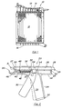
- the present invention is applicable to a radiator 10 of a type as shown in Figure 1 which consists of a core block 12 made up of many longitudinally extending bellows-shaped aluminum tubes having their upper ends formed in holes in a tube plate 17 (see Figure 3) and sealed against radiator fluid leakage by means of a snug titting passage through a resilient gasket 19 lying flush with and on top of the tube plate 17.
- the radiator 10 has plastic tanks 14 and 16 mounted on either end thereof and held secure by means of a plurality of tabs 18 bent over a flange 33 on each of the tanks 14 and 16. The tabs 18 keep the bottom of the tank flange 33 in sealing contact with the gasket 19 to effect a water tight seal between the tank 14 and the tube plate 17.
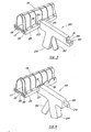
- the present implement 20 as shown in Figure 2 provides a means whereby the tabs 18 can be lifted allowing the tank to be removed for access to the gasket 19 and the tube plate 17 for repair.
- the implement 20 consists of a casing 22 made of two removable halves having an elongated channel 26 therethrough, a trigger handle 24, a trigger chamber 25, a spring chamber 40 and a flange gripping finger slot 48.
- the moveable parts that are mounted inside the casing 22 consist of an elongated tool member 28 slidable within the channel 26 and having a tab lifting finger 29 at one end and a tab crimping tace 31 on the end opposite the tab lifting finger 29.
- the elongated tool member 28 is mounted so that the tab lifting finger 29 is proximate a tab lifting end 23 of the casing 22 and the tab crimping face 31 is proximate a tab crimping end 27 of the casing 22.
- a bottom sliding surface of the elongated tool member 28 has a downwardly bent spring stop 36.
- a trigger 30 is rotatably mounted about shaft 32 in trigger chamber 25 and has an upper end 34 which extends through a hole in the elongated tool member 28 left by the downwardly bent spring stop 36.
- the trigger 30 has a contact surface 44 for contacting adaptor piece 38 intermediate the elongated tool member 28 and a contact surface 44.
- a spring 42 is mounted in the spring chamber 40 and has one end coupled to the spring stop 36 urging the latter toward the tab lifting end 23 of the casing.
- a flange gripping finger 46 is inserted into slot 48 in the spring chamber 40 and extends outwardly of crimping end 27 and terminates in an upwardly bent finger 50.
- a plurality of screw holes 52, 54, 56 and 58 are provided to attach the two halves of the casing 22 together.
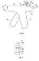
- FIG. 3 shows the implement 20 as used in raising tabs 18 of a plate 25 that are bent around flange 33 of tank 14.
- the tab lifting finger 29 of the elongated tool member 28 is inserted between the tank wall 14 and an end of the tab 18.
- a tab lifting end 23 of the casing 22 abuts the vertical wall 25 of the plate.
- Trigger 30 is then pushed into trigger chamber 25 contained within trigger housing 24 thereby pulling the tool member 28 back into the casing 20. This force results in lifting of the tab 18 into an upright position.
- This procedure is repeated for each tab in succession until all of the tabs are in an upright position. Once all of the tabs have been lifted, the tank 14 can easily be removed thereby permitting access to the resilient seal 19 and the tube plate 17.
- the tank is put back into place on top of the resilient seal 19.
- the implement 20 is then positioned so that the bent portion 50 of its flange gripping finger 46 contacts interior wall 35.
- elongated tool member 28 moves so that the tab crimping end 31 pushes the tab onto the flange 33 of the tank 14. This procedure is again repeated until all of the tabs have been pressed onto the flange, thereby completing repair of the radiator.
- a variant of the implement shown in Figures 5 and 6 includes a raised casing portion 60 along a casing barrel 70 having a flange abutting shoulder 62.
- a tab bender bar 64 integral with said elongated tool member 28 is movable along a bar slot 69 in the casing barrel 70 from a position remote from shoulder 62 to a position adjacent the latter in response to pivotal movement of trigger 30 into housing 24.
- shoulder 62 is positioned abutting a flange 68 while bar 64 contacts a raised tab 66. Depression of trigger 30 causes bar 64 to move toward shoulder 62 and bend tab 66 to a flat position onto flange 68.
Landscapes
- Engineering & Computer Science (AREA)
- Mechanical Engineering (AREA)
- Physics & Mathematics (AREA)
- Thermal Sciences (AREA)
- General Engineering & Computer Science (AREA)
- Manufacturing Of Electrical Connectors (AREA)
- Heat-Exchange Devices With Radiators And Conduit Assemblies (AREA)
- Hand Tools For Fitting Together And Separating, Or Other Hand Tools (AREA)
Applications Claiming Priority (2)
| Application Number | Priority Date | Filing Date | Title |
|---|---|---|---|
| US59595284A | 1984-04-02 | 1984-04-02 | |
| US595952 | 1984-04-02 |
Publications (2)
| Publication Number | Publication Date |
|---|---|
| EP0159162A2 true EP0159162A2 (de) | 1985-10-23 |
| EP0159162A3 EP0159162A3 (de) | 1986-05-14 |
Family
ID=24385388
Family Applications (1)
| Application Number | Title | Priority Date | Filing Date |
|---|---|---|---|
| EP85302285A Withdrawn EP0159162A3 (de) | 1984-04-02 | 1985-04-02 | Werkzeug zum Aufbiegen von Falzen |
Country Status (2)
| Country | Link |
|---|---|
| EP (1) | EP0159162A3 (de) |
| JP (1) | JPS60244434A (de) |
Cited By (1)
| Publication number | Priority date | Publication date | Assignee | Title |
|---|---|---|---|---|
| CN111486623A (zh) * | 2020-04-15 | 2020-08-04 | 绍兴集知汇信息科技有限公司 | 一种改进型空调冷凝器 |
Family Cites Families (3)
| Publication number | Priority date | Publication date | Assignee | Title |
|---|---|---|---|---|
| US2233937A (en) * | 1938-06-25 | 1941-03-04 | Andrew M Hexdall | Portable sheet metal bending tool |
| US3180128A (en) * | 1963-10-24 | 1965-04-27 | Ottis V Faulkner | Crimping tool |
| GB2035168A (en) * | 1978-11-30 | 1980-06-18 | Centico Ltd | Machine for aiding radiator repairs |
-
1985
- 1985-04-02 JP JP6860885A patent/JPS60244434A/ja active Pending
- 1985-04-02 EP EP85302285A patent/EP0159162A3/de not_active Withdrawn
Cited By (2)
| Publication number | Priority date | Publication date | Assignee | Title |
|---|---|---|---|---|
| CN111486623A (zh) * | 2020-04-15 | 2020-08-04 | 绍兴集知汇信息科技有限公司 | 一种改进型空调冷凝器 |
| CN111486623B (zh) * | 2020-04-15 | 2021-12-21 | 江苏百年制冷设备有限公司 | 一种改进型空调冷凝器 |
Also Published As
| Publication number | Publication date |
|---|---|
| EP0159162A3 (de) | 1986-05-14 |
| JPS60244434A (ja) | 1985-12-04 |
Similar Documents
| Publication | Publication Date | Title |
|---|---|---|
| US4614106A (en) | Tab lifting and crimping tool | |
| CN111958240B (zh) | 双扣软管内塞组装系统 | |
| US2436278A (en) | Pivoted tool for bending the edge of a panel about a supporting flange | |
| EP0159162A2 (de) | Werkzeug zum Aufbiegen von Falzen | |
| CN1050792C (zh) | 自动的自调夹钳或板手 | |
| US5657656A (en) | Automatic positioning system for a hose assembly and method therefor | |
| US4769891A (en) | Hand tool for tube fittings | |
| CN119920656A (zh) | 一种用于断路器触头的自动化装配设备 | |
| JP3803926B2 (ja) | 心線結線装置 | |
| US4819911A (en) | Clamp for gripping a flexible member | |
| US4974441A (en) | Ductwork clip uncrimper | |
| GB2035168A (en) | Machine for aiding radiator repairs | |
| US4823455A (en) | Radiator crimping and decrimping tools | |
| CN109434449B (zh) | 一种压前插端子上保险机构 | |
| CN2048009U (zh) | 活塞环涨钳 | |
| CN218216084U (zh) | 扭线装置 | |
| US4488424A (en) | Puller and cable bender employing socket wrench means | |
| US4847970A (en) | Radiator repair fixture | |
| CN212735821U (zh) | 单手自调管子扳手 | |
| US4411414A (en) | Radiator recoring fixturing and tools | |
| US4506440A (en) | Wiring tool for wiring electric multi-pin plug-in connectors, connector strips or the like using clamp-cutting techniques | |
| US4108486A (en) | Inflatable thrust producing tool | |
| CN223790259U (zh) | 一种可快速调节钳口的水泵钳 | |
| CN208495607U (zh) | 弯管零件的夹装工具 | |
| CN218693343U (zh) | 下料辅助定位装置 |
Legal Events
| Date | Code | Title | Description |
|---|---|---|---|
| PUAI | Public reference made under article 153(3) epc to a published international application that has entered the european phase |
Free format text: ORIGINAL CODE: 0009012 |
|
| AK | Designated contracting states |
Designated state(s): AT BE CH DE FR GB IT LI LU NL SE |
|
| PUAL | Search report despatched |
Free format text: ORIGINAL CODE: 0009013 |
|
| AK | Designated contracting states |
Kind code of ref document: A3 Designated state(s): AT BE CH DE FR GB IT LI LU NL SE |
|
| STAA | Information on the status of an ep patent application or granted ep patent |
Free format text: STATUS: THE APPLICATION IS DEEMED TO BE WITHDRAWN |
|
| 18D | Application deemed to be withdrawn |
Effective date: 19861115 |