EP0159028B1 - Magnetic thin film - Google Patents
Magnetic thin film Download PDFInfo
- Publication number
- EP0159028B1 EP0159028B1 EP85104637A EP85104637A EP0159028B1 EP 0159028 B1 EP0159028 B1 EP 0159028B1 EP 85104637 A EP85104637 A EP 85104637A EP 85104637 A EP85104637 A EP 85104637A EP 0159028 B1 EP0159028 B1 EP 0159028B1
- Authority
- EP
- European Patent Office
- Prior art keywords
- thin film
- magnetic
- magnetic thin
- weight percent
- elements
- Prior art date
- Legal status (The legal status is an assumption and is not a legal conclusion. Google has not performed a legal analysis and makes no representation as to the accuracy of the status listed.)
- Expired - Lifetime
Links
Images


Classifications
-
- G—PHYSICS
- G11—INFORMATION STORAGE
- G11B—INFORMATION STORAGE BASED ON RELATIVE MOVEMENT BETWEEN RECORD CARRIER AND TRANSDUCER
- G11B5/00—Recording by magnetisation or demagnetisation of a record carrier; Reproducing by magnetic means; Record carriers therefor
- G11B5/127—Structure or manufacture of heads, e.g. inductive
- G11B5/31—Structure or manufacture of heads, e.g. inductive using thin films
-
- H—ELECTRICITY
- H01—ELECTRIC ELEMENTS
- H01F—MAGNETS; INDUCTANCES; TRANSFORMERS; SELECTION OF MATERIALS FOR THEIR MAGNETIC PROPERTIES
- H01F10/00—Thin magnetic films, e.g. of one-domain structure
- H01F10/08—Thin magnetic films, e.g. of one-domain structure characterised by magnetic layers
- H01F10/10—Thin magnetic films, e.g. of one-domain structure characterised by magnetic layers characterised by the composition
- H01F10/18—Thin magnetic films, e.g. of one-domain structure characterised by magnetic layers characterised by the composition being compounds
-
- C—CHEMISTRY; METALLURGY
- C23—COATING METALLIC MATERIAL; COATING MATERIAL WITH METALLIC MATERIAL; CHEMICAL SURFACE TREATMENT; DIFFUSION TREATMENT OF METALLIC MATERIAL; COATING BY VACUUM EVAPORATION, BY SPUTTERING, BY ION IMPLANTATION OR BY CHEMICAL VAPOUR DEPOSITION, IN GENERAL; INHIBITING CORROSION OF METALLIC MATERIAL OR INCRUSTATION IN GENERAL
- C23C—COATING METALLIC MATERIAL; COATING MATERIAL WITH METALLIC MATERIAL; SURFACE TREATMENT OF METALLIC MATERIAL BY DIFFUSION INTO THE SURFACE, BY CHEMICAL CONVERSION OR SUBSTITUTION; COATING BY VACUUM EVAPORATION, BY SPUTTERING, BY ION IMPLANTATION OR BY CHEMICAL VAPOUR DEPOSITION, IN GENERAL
- C23C14/00—Coating by vacuum evaporation, by sputtering or by ion implantation of the coating forming material
- C23C14/06—Coating by vacuum evaporation, by sputtering or by ion implantation of the coating forming material characterised by the coating material
-
- C—CHEMISTRY; METALLURGY
- C23—COATING METALLIC MATERIAL; COATING MATERIAL WITH METALLIC MATERIAL; CHEMICAL SURFACE TREATMENT; DIFFUSION TREATMENT OF METALLIC MATERIAL; COATING BY VACUUM EVAPORATION, BY SPUTTERING, BY ION IMPLANTATION OR BY CHEMICAL VAPOUR DEPOSITION, IN GENERAL; INHIBITING CORROSION OF METALLIC MATERIAL OR INCRUSTATION IN GENERAL
- C23C—COATING METALLIC MATERIAL; COATING MATERIAL WITH METALLIC MATERIAL; SURFACE TREATMENT OF METALLIC MATERIAL BY DIFFUSION INTO THE SURFACE, BY CHEMICAL CONVERSION OR SUBSTITUTION; COATING BY VACUUM EVAPORATION, BY SPUTTERING, BY ION IMPLANTATION OR BY CHEMICAL VAPOUR DEPOSITION, IN GENERAL
- C23C14/00—Coating by vacuum evaporation, by sputtering or by ion implantation of the coating forming material
- C23C14/06—Coating by vacuum evaporation, by sputtering or by ion implantation of the coating forming material characterised by the coating material
- C23C14/0623—Sulfides, selenides or tellurides
-
- C—CHEMISTRY; METALLURGY
- C23—COATING METALLIC MATERIAL; COATING MATERIAL WITH METALLIC MATERIAL; CHEMICAL SURFACE TREATMENT; DIFFUSION TREATMENT OF METALLIC MATERIAL; COATING BY VACUUM EVAPORATION, BY SPUTTERING, BY ION IMPLANTATION OR BY CHEMICAL VAPOUR DEPOSITION, IN GENERAL; INHIBITING CORROSION OF METALLIC MATERIAL OR INCRUSTATION IN GENERAL
- C23C—COATING METALLIC MATERIAL; COATING MATERIAL WITH METALLIC MATERIAL; SURFACE TREATMENT OF METALLIC MATERIAL BY DIFFUSION INTO THE SURFACE, BY CHEMICAL CONVERSION OR SUBSTITUTION; COATING BY VACUUM EVAPORATION, BY SPUTTERING, BY ION IMPLANTATION OR BY CHEMICAL VAPOUR DEPOSITION, IN GENERAL
- C23C30/00—Coating with metallic material characterised only by the composition of the metallic material, i.e. not characterised by the coating process
-
- G—PHYSICS
- G11—INFORMATION STORAGE
- G11B—INFORMATION STORAGE BASED ON RELATIVE MOVEMENT BETWEEN RECORD CARRIER AND TRANSDUCER
- G11B5/00—Recording by magnetisation or demagnetisation of a record carrier; Reproducing by magnetic means; Record carriers therefor
- G11B5/127—Structure or manufacture of heads, e.g. inductive
- G11B5/147—Structure or manufacture of heads, e.g. inductive with cores being composed of metal sheets, i.e. laminated cores with cores composed of isolated magnetic layers, e.g. sheets
-
- H—ELECTRICITY
- H01—ELECTRIC ELEMENTS
- H01F—MAGNETS; INDUCTANCES; TRANSFORMERS; SELECTION OF MATERIALS FOR THEIR MAGNETIC PROPERTIES
- H01F10/00—Thin magnetic films, e.g. of one-domain structure
- H01F10/08—Thin magnetic films, e.g. of one-domain structure characterised by magnetic layers
- H01F10/10—Thin magnetic films, e.g. of one-domain structure characterised by magnetic layers characterised by the composition
- H01F10/12—Thin magnetic films, e.g. of one-domain structure characterised by magnetic layers characterised by the composition being metals or alloys
- H01F10/14—Thin magnetic films, e.g. of one-domain structure characterised by magnetic layers characterised by the composition being metals or alloys containing iron or nickel
- H01F10/142—Thin magnetic films, e.g. of one-domain structure characterised by magnetic layers characterised by the composition being metals or alloys containing iron or nickel containing Si
- H01F10/145—Thin magnetic films, e.g. of one-domain structure characterised by magnetic layers characterised by the composition being metals or alloys containing iron or nickel containing Si containing Al, e.g. SENDUST
-
- G—PHYSICS
- G11—INFORMATION STORAGE
- G11B—INFORMATION STORAGE BASED ON RELATIVE MOVEMENT BETWEEN RECORD CARRIER AND TRANSDUCER
- G11B5/00—Recording by magnetisation or demagnetisation of a record carrier; Reproducing by magnetic means; Record carriers therefor
- G11B5/127—Structure or manufacture of heads, e.g. inductive
- G11B5/31—Structure or manufacture of heads, e.g. inductive using thin films
- G11B5/3109—Details
-
- Y—GENERAL TAGGING OF NEW TECHNOLOGICAL DEVELOPMENTS; GENERAL TAGGING OF CROSS-SECTIONAL TECHNOLOGIES SPANNING OVER SEVERAL SECTIONS OF THE IPC; TECHNICAL SUBJECTS COVERED BY FORMER USPC CROSS-REFERENCE ART COLLECTIONS [XRACs] AND DIGESTS
- Y10—TECHNICAL SUBJECTS COVERED BY FORMER USPC
- Y10T—TECHNICAL SUBJECTS COVERED BY FORMER US CLASSIFICATION
- Y10T428/00—Stock material or miscellaneous articles
- Y10T428/12—All metal or with adjacent metals
- Y10T428/12431—Foil or filament smaller than 6 mils
Definitions
- This invention relates to a magnetic thin film consisting essentially of Fe, Al and Si and also containing oxygen.
- the Sendust alloy thin film can be applied to the magnetic recording head which can record the signals on the magnetic recording medium having high coercive force, such as the aforementioned metal powder tape.
- the Sendust alloy thin film is inferior e,g. to ferrite in abrasion resistance and, being a metal material, it is relatively easy to rust.
- saturation magnetic flux density Bs of the Sendust alloy thin film may cause saturation magnetic flux density Bs of the Sendust alloy thin film to be lowered.
- the saturation magnetic flux density of the Sendust alloy thin film free of the aforementioned additives amounts to ca. 11000 Gauss
- the saturation magnetic flux density of the Sendust alloy thin film containing these additives amounts to ca. 9000 Gauss.
- Such reduction in the saturation magnetic flux density Bs is unfavorable with the magnetic recording medium having the high coercive force Hc such as metal powder tape.
- Non-crystalline magnetic alloys that are high in saturation magnetic flux density Bs and are not affected in magnetic permeability in the high frequency region.
- these non-crystalline magnetic alloys are unstable at high temperatures and are deteriorated markedly in magnetic permeability due to prolongated heating or heat cycles with a resultingly lowered reproducing efficiency.
- the materials can not be subjected to a temperature higher than 500°C for prolonged time, because the materials can be crystallized under these conditions.
- amorphous magnetic alloys for the preparation of magnetic heads which may involve the processing step at a temperature higher than 500°C, such as glass bonding.
- JP-A-58-82 506 a magnetic thin film material is known on the basis of a Al-Si-Fe-alloy comprising a platinum group element and one or two or more of group Va elements, which has superior magnetic characteristics, corrosion resistance, abrasion resistance and improved conformability with a substrate.
- JP-A-58-82 507 discloses a similar magnetic thin film material comprising an Al-Si-Fe-alloy containing as an additional element a platinum group element and one or more of group IVa elements and having improved mechanical and magnetic characteristics.
- JP-A-58-188 318 discloses a magnetic head having enhanced reliability and durability by comprising a Fe-Si-Al-alloy into the surface of which ions of Cr, Ti, Zr, Nb, Ru, Rh, Pd, Os, In, Pt, O or N are implanted to improve the wear resistance. It is stated that O and N enhance the wear resistance by forming oxides and nitrides, respectively. It is furtheron stated that the magnetic properties are not deteriorated by adjusting the thickness of the ion implanted layer to ⁇ 10 ⁇ m.
- the problem to be solved by the present invention therefore is the provision of a magnetic thin film having improved frequency characteristics of the magnetic permeability besides improved hardness, abrasion resistance and corrosion resistance.
- T is at least one element selected from the group consisting of IIIa group elements, IVa group elements, Va group elements, VIIa group elements
- Fig. 1 is a characteristic diagram showing the relation between the O contents in the Fe-Al-Si alloy thin film and the Vickers hardness.
- Fig. 2 is a characteristic diagram showing the relation between the O contents in the Fe-Al-Si alloy thin film and the specific resistivity with the resistivity of the O-free Fe-Al-Si alloy thin film being one.
- Fig. 3 is a characteristic diagram shown the relation between O contents in the Fe-Al-Si alloy thin film and magnetic permeability at 1MHz.
- Fig. 4 is a characteristic diagram showing frequency characteristics of magnetic permeability of the O-containing Fe-Al-Si alloy thin film.
- Fig.5 is a characteristic diagram showing the relation between the contents of O in the Fe-Al-Si alloy thin film and the saturation magnetic flux density.
- the magnetic thin film of the present invention consists essentially of Fe, Al and Si and, more importantly, it also contains oxygen (O).
- the content of oxygen (O) in the magnetic thin film of the present invention is preferably in the range from 0.3 to 3.8 weight percent. With a content less than 0.3 weight percent, a sufficient effect can not be expected. With a content higher than 3.8 weight percent, the magnetic permeability may be lowered and the coercive force Hc increased. In addition to oxygen O, nitrogen may also be contained in the magnetic thin film.
- the preferred contents of the three main components of the magnetic thin film are such that the contents of Al and Si be 2 to 10 weight percent and 4 to 15 weight percent, respectively, the balance being Fe. That is,when the composition of the magnetic thin film is expressed as Fe a Al b Si c O d , where a, b, c and d denote weight ratio values of the respective components, the composition given by the following expressions 70 ⁇ a ⁇ 95, 2 ⁇ b ⁇ 10, 4 ⁇ c ⁇ 15 and 0.3 ⁇ d ⁇ 3.8 is preferred. With the Al or Si contents higher or lower than the above specified value, the magnetic properties of the magnetic thin film are deteriorated.
- part of Fe be replaced by Co and/or Ni.
- part of Fe can be replaced by Co for elevating the saturation magnetic flux density Bs.
- a maximum value of the saturation magnetic flux density Bs may be obtained with a composition in which 40 weight percent of Fe is replaced by Co. It is preferred that the ratio of substitution by Co be in the range of 0 to 60 weight percent related to Fe.
- part of Fe may be replaced by Ni for maintaining a higher value of magnetic permeability without decreasing the saturation magntic flux density. It is preferred that the ratio of substitution by Ni be in the range of 0 to 40 weight percent related to Fe.
- additives can be added to the magnetic thin film as additions for improving rust-proofness and abrasion resistance.
- These additives may include IIIa group elements including elements of lanthanum series such as Sc, Y, La Ce, Nd or Gd, IVa group elements such as Ti, Zr or Hf, Va group elements such as V, Nb or Ta, VIa group elements such as Cr, Mo or W, VIIa group elements such as Mn, Tc or Re, Ib group elements such as Cu, Ag or Au, and other elements such as Ga, In, Ge, Sn or Sb.
- IIIa group elements including elements of lanthanum series such as Sc, Y, La Ce, Nd or Gd, IVa group elements such as Ti, Zr or Hf, Va group elements such as V, Nb or Ta, VIa group elements such as Cr, Mo or W, VIIa group elements such as Mn, Tc or Re, Ib group elements such as Cu, Ag or Au, and other elements such as Ga, In, Ge, Sn or Sb.
- a, b, c, d and e denote the weight ratio values of the associated components and T denotes the aforementioned additive. With the amount of the additive in excess of 10 weight percent, magnetic properties of the magnetic thin film tend to be lowered.
- the elements of the platinum group such as Ru, Rh, Pd, Os, Ir or Pt may be used as the additive either singly or as an admixture. These platinum group elements may be added in an amount less than 40 weight percent. If these elements are added in an amount more than 40 weight percent, the magnetic properties of the magnetic thin film tend to be lowered.
- both the aforementioned additive such as the elements of the IIIa or IVa groups and the elements of the platinum group may be used in combination.
- a, b, c, d, e and f denote weight ratio values of the associated components
- T denotes the aforementioned additive such as IIIa or IVa group elements
- P the aforementioned platinum group elements.
- the film thickness of the magnetic thin film having the above composition is preferably more than 1nm (10 ⁇ ) and less than 1mm and more preferably more than 1nm (10 ⁇ ) and less than 100 ⁇ m.
- high magnetic permeability and high hardness may be achieved with the magnetic thin film of the present invention by reason of the content of oxygen (O) without deterioration in the magnetic properties such as saturation magnetic flux density or coercive force.
- the contents of oxygen (O) give rise to an increased specific resistivity and a lowerd eddy current loss in the high frequency region so that the frequency characteristics of the magnetic permeability are improved with the result that the film may be effectively used with the magnetic heads used in a frequency region higher than 10 MHz.
- the magnetic thin film with the content of oxygen (O) as described above is also superior in durability. For example, no rust formation was observed on the film immersed in city water for three days.
- the drastically increased film hardness is possibly ascribable to the generation of the high hardness particles, such as oxide of Fe, alumina or silicon dioxide particles.
- the magnetic thin film is prepared by, for example, physical vapor deposition.
- the methods of physical vapor deposition may include flash vacuum evaporation, reactive vacuum evaporation, ion plating, sputtering or a cluster ion beaming. Deposition and ion implantation may also be carried out simultaneously. In introducing oxygen O into the magnetic thin film, the following methods may be used.
- the following methods may be employed.
- the target composition was Fe82 Al7 Si11.
- a sputtering operation was carried out with the addition of oxygen (O2) into an Ar as the inert gas.
- O2 oxygen
- the ratio of O2 in the inert gas was changed by controlling the partial pressure of the O2 gas which is an index of the O2 ratio in the inert gas.
- the Fe-Al-Si alloy thin film was formed on the crystallized glass substrate. After heat-treating the resulting Fe-Al-Si alloy thin film at 550°C for one hour, the hardness, specific resistivity, magnetic permeability and saturation magnetic flux density were measured.
- Fig.1 In the characteristic diagram of Fig.1, there is shown the relation between the hardness and the ratio of O contained in the Fe-Al-Si alloy thin film.
- the hardness was measured herein in terms of the Vickers hardness and with a weight of 50g applied for 15 seconds for weighting.
- the hardness of the Fe-Al-Si alloy thin film is appreciably increased.
- the hardness Hv of the Fe-Al-Si alloy film completely free of O amounts to 630
- the hardness Hv of the Fe-Al-Si alloy thin film with contents of3.8 weight percent of O amounts to 1000.
- Fig. 2 In the characteristic diagram shown in Fig. 2, there is shown the relation between the electrical resistace (specific resistivity) and the ratio of O in the Fe-Al-Si alloy thin film. It should be noted that the electrical resistance was measured by the four-terminal method and as the specific resistivity with the electrical resistance of the O-free Fe-Al-Si alloy thin film as 1.0.
- This specific resistivity is a critical factor for estimating magnetic permeability of the Fe-Al-Si alloy thin film in the high frequency region.
- a coaxial like induction current eddy current
- eddy current flows in the magnetic body by the temporally changing magnetic flux, such eddy current causing a power consumption known as eddy current loss.
- This eddy current loss is markedly related with the frequency and the resistivity of the magnetc material and gives rise to decreased permeability especially in the high frequency region. It is known for example that magnetic permeability of the ordinary Sendust alloy material tends to be lowered in the high frequency region, since the resistivity of the material is 85 ⁇ cm which is much lower than that of the amorphous alloy material which is 150 ⁇ cm.
- the larger resistivity of the resulting Fe-Al-Si alloy thin film is preferred. It is seen from Fig.2 that, with the increase in the O ratio, the specific resistivity of the Fe-Al-Si alloy thin film is linearly increased. It is therefore presumed that O-containing the Fe-Al-Si alloy film is also excellent in magnetic permeability in the high frequency region.
- FIG. 3 In the characteristic diagram shown in Fig. 3, there is shown the relation between the O ratio in the Fe-Al-Si alloy film and magnetic permeability at 1 MHz. Measurement of magnetic permeability was made with the aid of a permiance meter. It is seen from Fig.3 that magnetic permeability of the Fe-Al-Si alloy thin film is notably increased with increase in the O ratio. For instance,with the O ratio of 1 weight percent, magnetic permeability is improved by a factor of about 2.5.
- Fig.4 shows frequency characteristics of magnetic permeability of the O-containing Fe-Al-Si alloy thin film.
- the curve a represents the frequency characteristics for O contents of 0 weight percent
- the curve b those for O contents of 0.3 weight percent
- the curve c those for O contents of 1.0 weight percent
- the curve d those for O contents of 2.4 weight percent
- the curve e those for O contents of 3.8 weight percent
- the curve f those for O contents of 4.9 weight percent.
- the Fe-Al-Si alloy thin film with O contents exhibits a higher magnetic permeability in any frequency than that without O contents. Above all, it may be appreciated that decrease in magnetic permeability in the higher frequency tends to be reduced with increase in the O contents.
- the alloy thin film with O contents of 4.9 weight percent may be sufficiently employed in the frequency range of 20 to 30 MHz, although it exhibits a low magnetic permeability in the frequency region less than 10 MHz.
- the saturation magnetic flux density of the Fe-Al-Si alloy thin film is increased by the addition of O into the film. This may be highly meritorious in consideration that the saturation magnetic flux density is generally lowered by using additives aimed to improve hardness or temperature characteristics of the magnetic permeability. In the present Example, not only the reduction in the saturation magnetic flux density is prevented, but the saturation magnetic flux density is improved.
- the Fe-Al-Si alloy thin film is not only superior in hardness, rust-proofness or durability but also superior in magnetic characteristics such as permeability or saturation magnetic flux density and hence may be advantageously used e.g. in conjunction with magnetic heads.
- the resulting Fe-Al-Si alloy thin film was heat-treated at 350° C to 800° C for 1-5 hours. Then, magnetic permeability of the film was measured with the aid of a permiance meter and the Vickers hardness was also measured with weighting of 50g.
- the composition of the resulting Fe-Al-Si alloy thin film was analyzed as to Fe, Al and Si contents with the aid of an X-ray micro-analyzer. The oxygen contents were measured by the gas analysis of the magnetic thin film formed on the Ni substrate. The results are shown in Table 1. TABLE 1 composition (wt.%) permeability Vickers hardness Fe Al Si O 1MHz 5MHz comp.
- sample 1 94.8 2.1 3.1 0 260 220 580 sample 1 (94.8 2.1 3.1) x0.978 2.2 360 310 690 comp.
- sample 2 91.6 2.6 5.8 0 390 330 650 sample 2 (91.6 2.6 5.8) x0.978 2.2 460 400 780 comp.
- sample 3 87.1 9.8 3.3 0 280 240 620 sample 3 (87.1 9.8 3.3) x0.978 2.2 390 320 750 comp.
- sample 4 85.1 5.6 9.3 0 2300 1820 660 sample 4 (85.1 5.6 9.3) x0.978 2.2 4320 2880 860 comp.
- sample 5 82.4 8.2 9.4 0 1550 1450 770 sample 5 (82.4 8.2 9.4) x0.978 2.2 1720 1030 870 comp.
- sample 6 80.4 8.7 10.9 0 270 200 590 sample 6 (80.4 8.7 10.9) x0.978 2.2 1580 1310 950 comp. sample 7 86.3 2.4 11.3 0 380 330 700 sample 7 (86.3 2.4 11.3) x0.978 2.2 490 470 980 comp. sample 8 78.1 8.2 13.7 0 110 90 640 sample 8 (78.1 8.2 13.7) x0.978 2.2 640 600 960 comp. sample 9 78.7 6.3 15.0 0 100 70 800 sample 9 (78.7 6.3 15.0) x0.978 2.2 650 600 1050 comp. sample 10 74.6 9.7 15.7 0 50 45 780 sample 10 (74.6 9.7 15.7) x0.978 2.2 260 240 1010
- a composite target consisting of a pure iron target on which Al, Si and Co or Ni were mounted was used as target and the sputtering operation was carried out in an O2-containing Ar gas and in an O2-free Ar gas for the preparation of the Fe-Al-Si alloy thin film.
- Silicion (Si) with the purity of 99.9999 percent, aluminum (Al) with the purity of 99.99 percent and iron (Fe) with the purity of 99.99 percent were used as the starting materials. These starting materials were separately prepared in such weight amounts as to give a predetermined relative composition. The resulting batch was smelted in vacuum by using a high frequency smelting oven. The resulting molten product was poured into a mold for the preparaton of the alloy target.
- the saturation magnetic flux density and the coercive force were also measured in the above Examples and comparative Examples and were found to be substantially unchanged no matter whether or not oxygen was contained in the film samples.
- the saturation magnetic flux density and the coercive force of the comparative sample 13 amount to 1.1 T (11000 gauss) and 24 A/m (0.3 oersted), respectively, the saturation magnetic flux density of the sample 13 amounts to 1.1 T (11000 gauss) and the coercive force of the same sample amounts to 24 A/m (0.3 oersted).
- the present invention allows to provide a magnetic thin film high in hardness and superior in magnetic properties.
Landscapes
- Chemical & Material Sciences (AREA)
- Engineering & Computer Science (AREA)
- Chemical Kinetics & Catalysis (AREA)
- Materials Engineering (AREA)
- Mechanical Engineering (AREA)
- Metallurgy (AREA)
- Organic Chemistry (AREA)
- Power Engineering (AREA)
- Manufacturing & Machinery (AREA)
- Thin Magnetic Films (AREA)
- Soft Magnetic Materials (AREA)
- Magnetic Record Carriers (AREA)
Description
- This invention relates to a magnetic thin film consisting essentially of Fe, Al and Si and also containing oxygen.
- In magnetic recording apparatus such as,for example, video tape recorders (VTRs), researches are being made towards increasing the recording density and the frequency of the recording signals. In keeping pace with the tendency towards high density recording,so-called metal powder tapes making use of the powders of the ferromagnetic metals,such as Fe, Co or Ni, as magnetic powders, or so-called evaporated metal tapes in which the ferromagnetic metal material is deposited on the base film, are also used as the magnetic recording medium. By reason of the high coercive force Hc of said magnetic recording medium, head materials of the magnetic head for both recording and replaying are also required to have a high saturation magnetic flux density Bs. For instance, the ferrite material used frequently as low in saturation magnetic flux density Bs, whereas permalloy presents a problem in abrasion resistance.
- On the other hand, in keeping pace with the above described tendency towards high density recording, researches are also made towards reducing the track width of the magnetic patterns on the magnetic recording medium, and the magnetic heads are required to be correspondingly narrow in track width.
- It has been suggested to use a so-called composite type magnetic head wherein insulating films and magnetic thin film to be used subsequently as the magnetic core are alternately applied to a non-magnetic substrate, such as ceramic substrate so as to be used as track parts. It has been suggested to use a so-called thin film head in which the magnetic thin film and the electrically conductive thin films are deposited with the intermediary of thin insulation films for providing a multi-layered structure. Thus the general attention is directed to a Sendust alloy thin film consisting essentially of Fe, Al and Si as magnetic thin films employed in the type of the magnetic heads.
- Because of its high saturation magnetic flux density Bs and relatively high hardness, the Sendust alloy thin film can be applied to the magnetic recording head which can record the signals on the magnetic recording medium having high coercive force, such as the aforementioned metal powder tape.
- However, while being of relatively high hardness,the Sendust alloy thin film is inferior e,g. to ferrite in abrasion resistance and, being a metal material, it is relatively easy to rust.
- In this connection, method were devised in which elements or Ti, Cr or Nb or platinum group are added to the Sendust alloy thin film besides main components, that is, Fe, Al and Si,for preventing the occurrence of rust and elevating the hardness and abrasion resistance.
- However, it has been shown that addition of the aformentioned elements may cause saturation magnetic flux density Bs of the Sendust alloy thin film to be lowered. According to our experments, the saturation magnetic flux density of the Sendust alloy thin film free of the aforementioned additives amounts to ca. 11000 Gauss, whereas the saturation magnetic flux density of the Sendust alloy thin film containing these additives amounts to ca. 9000 Gauss. Such reduction in the saturation magnetic flux density Bs is unfavorable with the magnetic recording medium having the high coercive force Hc such as metal powder tape.
- In addition, when the metal material such as Sendust alloy thin film is used for the core of the magnetic head, there is presented a drawback that magnetic permeability is lowered in the high frequency region on account of the eddy current loss and hence a sufficient reproducing output is not achieved in the high frequency region.
- It has also been suggested to replace the Sendust alloy thin film by non-crystalline magnetic alloys (so-called amorphous magnetic alloys ) that are high in saturation magnetic flux density Bs and are not affected in magnetic permeability in the high frequency region. However, these non-crystalline magnetic alloys are unstable at high temperatures and are deteriorated markedly in magnetic permeability due to prolongated heating or heat cycles with a resultingly lowered reproducing efficiency. Above all, the materials can not be subjected to a temperature higher than 500°C for prolonged time, because the materials can be crystallized under these conditions.
- It is therefore not preferred to use the amorphous magnetic alloys for the preparation of magnetic heads which may involve the processing step at a temperature higher than 500°C, such as glass bonding.
- From Patent Abstracts of Japan, Vol. 7, no. 178 (E-191) (August 6, 1983), JP-A-58-82 506 a magnetic thin film material is known on the basis of a Al-Si-Fe-alloy comprising a platinum group element and one or two or more of group Va elements, which has superior magnetic characteristics, corrosion resistance, abrasion resistance and improved conformability with a substrate.
- Patent Abstracts of Japan, Vol. 7, no. 178 (E-191) (August 6, 1982), JP-A-58-82 507 discloses a similar magnetic thin film material comprising an Al-Si-Fe-alloy containing as an additional element a platinum group element and one or more of group IVa elements and having improved mechanical and magnetic characteristics.
- Patent Abstracts of Japan, Vol. 8, no. 33 (P-254)(February 14, 1984). JP-A-58-188 318 discloses a magnetic head having enhanced reliability and durability by comprising a Fe-Si-Al-alloy into the surface of which ions of Cr, Ti, Zr, Nb, Ru, Rh, Pd, Os, In, Pt, O or N are implanted to improve the wear resistance. It is stated that O and N enhance the wear resistance by forming oxides and nitrides, respectively. It is furtheron stated that the magnetic properties are not deteriorated by adjusting the thickness of the ion implanted layer to ≦ 10 µm.
- The problem to be solved by the present invention therefore is the provision of a magnetic thin film having improved frequency characteristics of the magnetic permeability besides improved hardness, abrasion resistance and corrosion resistance.
- It has now been found that by uniformly introducing a specific amount of oxygen in a Fe-Al-Si-based alloy this problem can be solved.
- The subject matter of the present invention therefore is a magnetic thin film having a composition represented by the following formula:

wherein T is at least one element selected from the group consisting of IIIa group elements, IVa group elements, Va group elements, VIIa group elements, Ib group elements, Ga, In, Ge, Sn and Sb, P is at least one of platinum group elements, a, b, c, d, e and f each represents a weight percent of the respective element and satisfies the following relation




with a+b+c+d+e+f= 100, wherein the oxygen is uniformly distributed in said magnetic thin film. - Fig. 1 is a characteristic diagram showing the relation between the O contents in the Fe-Al-Si alloy thin film and the Vickers hardness.
- Fig. 2 is a characteristic diagram showing the relation between the O contents in the Fe-Al-Si alloy thin film and the specific resistivity with the resistivity of the O-free Fe-Al-Si alloy thin film being one.
- Fig. 3 is a characteristic diagram shown the relation between O contents in the Fe-Al-Si alloy thin film and magnetic permeability at 1MHz.
- Fig. 4 is a characteristic diagram showing frequency characteristics of magnetic permeability of the O-containing Fe-Al-Si alloy thin film.
- Fig.5 is a characteristic diagram showing the relation between the contents of O in the Fe-Al-Si alloy thin film and the saturation magnetic flux density.
- The magnetic thin film of the present invention consists essentially of Fe, Al and Si and, more importantly, it also contains oxygen (O).
- By the O content, magnetic permeability and hardness of the magnetic thin film are improved markedly.
- Our experiments have revealed that, with increase in the contents of oxygen in the magnetic thin film, magnetic permeability is markedly improved, and that, above all, with the oxygen contents equal to ca.1.5 weight percent, magnetic permeability may be increased by a factor of about 2 as compared to the oxygen free magnetic thin film. On the other hand, magnetic permeability is lowered with excess oxygen contents in the magnetic thin film. For example, with 1MHz frequency, the oxygen contents less than 4 weight percent are preferred. However, since the specific resistivity of the aforementioned magnetic thin film is increased with an increase in the oxygen content, it is considered that an oxygen content up to ca.0.5 weight percent may be practically usable in a higher frequency region, for example, in conjunction with magnetic heads for digital VTRs.
- Likewise, it has been shown that, with increase in the oxygen contents in the magnetic thin film, its Vickers hardness is also acutely increased and a substantially constant hardness is assured with the oxygen contents in excess of about 2 weight percent.
- Therefore, the content of oxygen (O) in the magnetic thin film of the present invention is preferably in the range from 0.3 to 3.8 weight percent. With a content less than 0.3 weight percent, a sufficient effect can not be expected. With a content higher than 3.8 weight percent, the magnetic permeability may be lowered and the coercive force Hc increased. In addition to oxygen O, nitrogen may also be contained in the magnetic thin film.
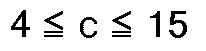
- The preferred contents of the three main components of the magnetic thin film, that is, Fe, Al and Si, are such that the contents of Al and Si be 2 to 10 weight percent and 4 to 15 weight percent, respectively, the balance being Fe. That is,when the composition of the magnetic thin film is expressed as Fe a Al b Si c O d, where a, b, c and d denote weight ratio values of the respective components, the composition given by the following expressions


is preferred. With the Al or Si contents higher or lower than the above specified value, the magnetic properties of the magnetic thin film are deteriorated. - It is possible that part of Fe be replaced by Co and/or Ni.
- It is also possible that part of Fe can be replaced by Co for elevating the saturation magnetic flux density Bs. Above all, a maximum value of the saturation magnetic flux density Bs may be obtained with a composition in which 40 weight percent of Fe is replaced by Co. It is preferred that the ratio of substitution by Co be in the range of 0 to 60 weight percent related to Fe.
- On the other hand, part of Fe may be replaced by Ni for maintaining a higher value of magnetic permeability without decreasing the saturation magntic flux density. It is preferred that the ratio of substitution by Ni be in the range of 0 to 40 weight percent related to Fe.
- Various other elements can be added to the magnetic thin film as additions for improving rust-proofness and abrasion resistance. These additives may include IIIa group elements including elements of lanthanum series such as Sc, Y, La Ce, Nd or Gd, IVa group elements such as Ti, Zr or Hf, Va group elements such as V, Nb or Ta, VIa group elements such as Cr, Mo or W, VIIa group elements such as Mn, Tc or Re, Ib group elements such as Cu, Ag or Au, and other elements such as Ga, In, Ge, Sn or Sb. These additives may be added either singly or as an admixture and in an amount of 0 to 10 weight percent related to the above described magnetic thin film. In this connection, when the magnetic thin film composition is expressed as

the composition is preferably such that the following expressions


are satisfied. In these expressions, a, b, c, d and e denote the weight ratio values of the associated components and T denotes the aforementioned additive. With the amount of the additive in excess of 10 weight percent, magnetic properties of the magnetic thin film tend to be lowered. - Alternately, the elements of the platinum group such as Ru, Rh, Pd, Os, Ir or Pt may be used as the additive either singly or as an admixture. These platinum group elements may be added in an amount less than 40 weight percent. If these elements are added in an amount more than 40 weight percent, the magnetic properties of the magnetic thin film tend to be lowered.
- Both the aforementioned additive such as the elements of the IIIa or IVa groups and the elements of the platinum group may be used in combination. In this case, when the magnetic thin film composition is expressed as

the composition is preferably such that the following expressions


are satisfried. In these expressions, a, b, c, d, e and f denote weight ratio values of the associated components, T denotes the aforementioned additive such as IIIa or IVa group elements and P the aforementioned platinum group elements. It should be noted that, when the elements of the platinum group the fifth period, that is, Ru, Rh, or Pd, are used as platinum group elements, preferably

- The film thickness of the magnetic thin film having the above composition is preferably more than 1nm (10 Å) and less than 1mm and more preferably more than 1nm (10 Å) and less than 100 µm.
- As described above high magnetic permeability and high hardness may be achieved with the magnetic thin film of the present invention by reason of the content of oxygen (O) without deterioration in the magnetic properties such as saturation magnetic flux density or coercive force. Above all, the contents of oxygen (O) give rise to an increased specific resistivity and a lowerd eddy current loss in the high frequency region so that the frequency characteristics of the magnetic permeability are improved with the result that the film may be effectively used with the magnetic heads used in a frequency region higher than 10 MHz.
- It has been found that the magnetic thin film with the content of oxygen (O) as described above is also superior in durability. For example, no rust formation was observed on the film immersed in city water for three days.
- Although it is not known precisely what role is played by the oxygen O in the magnetic thin film, it may be presumed that the drastically increased film hardness is possibly ascribable to the generation of the high hardness particles, such as oxide of Fe, alumina or silicon dioxide particles.
- Various methods may be possibly resorted to for the preparation of the magnetic thin film of the present invention. It is not possible to introduce a large amount of oxygen uniformly by resorting to, for example, the well-known smelting method, because the oxygen is then usually floated in the melting alloy as slug and separated as inclusion from the alloy.
- Therefore, the magnetic thin film is prepared by, for example, physical vapor deposition. The methods of physical vapor deposition may include flash vacuum evaporation, reactive vacuum evaporation, ion plating, sputtering or a cluster ion beaming. Deposition and ion implantation may also be carried out simultaneously. In introducing oxygen O into the magnetic thin film, the following methods may be used.
- (i) The aforementioned physical vapor deposition for example, may be effected in an atmosphere containing an oxygen gas and the content of the oxygen O in the resulting magnetic thin film is controlled by checking the concentration of the oxygen gas.
- (ii) A compound of oxygen and at least one element of the aforementioned composition and an alloy of the remaining components are used as a deposition source so that oxygen is be introduced into the resulting magnetic thin film.
- When adjusting the ratio values of the respective elements of the magnetic thin film, such as Fe, Al or Si, the following methods may be employed.
- (i) Fe, Al, Si, other additives and replacement metals are weighed so that a preset relative composition is satisfied. The respective components are previously smelted in e.q. an induction furnace for forming an alloy ingot which may be used as a deposition source.
- (ii) The deposition sources for the respective elements are prepared and the composition is controlled by activating the selected number of the deposition sources.
- (iii) The respective deposition sources of the component elements are provided and the input applied to these respectve sources (impressed voltage) is adjusted for controlling the deposition speed and hence the film composition.
- (iv) The alloy is used as the deposition source and other elements are implanted during deposition.
- The description with reference to several specific examples of the present invention is given hereinbelow. It should be noted that these examples are given only by may of illustration and are not intended for limiting the scope of the present invention.
- Silicon (Si) with the purity of 99.9999%, aluminum (Al) with the purity of 99.99% and iron (Fe) with the purity of 99.99%,were used as the starting materials. These materials were separately prepared in weighed out amounts and smelted in vacuum in a high frequency smelting oven. The resulting batch was poured into a mold and cast into a target for cathode which is 50mm in diameter and 1mm in thickness. The target composition was Fe₈₂ Al₇ Si₁₁.
- Under the following sputtering conditions, films were deposited in accordance with the planar magnetron type sputtering method by using the above target.
Sputtering Conditions RF input 100W distance between target and substrate 30mm substrate temperature ∼20°C(with water coolling) ultimate pressure 0.4 Pa (3 X 10⁻⁶ Torr)Ar gas pressure 0.53Pa (4 X 10⁻³ Torr)film thickness ca. 6 µm - In accordance with the above sputtering conditions, a sputtering operation was carried out with the addition of oxygen (O₂) into an Ar as the inert gas. During the sputtering operation, the ratio of O₂ in the inert gas was changed by controlling the partial pressure of the O₂ gas which is an index of the O₂ ratio in the inert gas. In this manner, the Fe-Al-Si alloy thin film was formed on the crystallized glass substrate. After heat-treating the resulting Fe-Al-Si alloy thin film at 550°C for one hour, the hardness, specific resistivity, magnetic permeability and saturation magnetic flux density were measured.
- In the characteristic diagram of Fig.1, there is shown the relation between the hardness and the ratio of O contained in the Fe-Al-Si alloy thin film. The hardness was measured herein in terms of the Vickers hardness and with a weight of 50g applied for 15 seconds for weighting.
- It can be seen from this figure that, with an increase in the ratio of O in the Fe-Al-Si alloy thin film, the hardness of the Fe-Al-Si alloy thin film is appreciably increased. For example, the hardness Hv of the Fe-Al-Si alloy film completely free of O amounts to 630, whereas the hardness Hv of the Fe-Al-Si alloy thin film with contents of3.8 weight percent of O amounts to 1000.
- In the characteristic diagram shown in Fig. 2, there is shown the relation between the electrical resistace (specific resistivity) and the ratio of O in the Fe-Al-Si alloy thin film. It should be noted that the electrical resistance was measured by the four-terminal method and as the specific resistivity with the electrical resistance of the O-free Fe-Al-Si alloy thin film as 1.0.
- This specific resistivity is a critical factor for estimating magnetic permeability of the Fe-Al-Si alloy thin film in the high frequency region. Thus, in general, a coaxial like induction current (eddy current) flows in the magnetic body by the temporally changing magnetic flux, such eddy current causing a power consumption known as eddy current loss. This eddy current loss is markedly related with the frequency and the resistivity of the magnetc material and gives rise to decreased permeability especially in the high frequency region. It is known for example that magnetic permeability of the ordinary Sendust alloy material tends to be lowered in the high frequency region, since the resistivity of the material is 85 µΩcm which is much lower than that of the amorphous alloy material which is 150 µΩcm. Therefore, the larger resistivity of the resulting Fe-Al-Si alloy thin film is preferred. It is seen from Fig.2 that, with the increase in the O ratio, the specific resistivity of the Fe-Al-Si alloy thin film is linearly increased. It is therefore presumed that O-containing the Fe-Al-Si alloy film is also excellent in magnetic permeability in the high frequency region.
- In the characteristic diagram shown in Fig. 3, there is shown the relation between the O ratio in the Fe-Al-Si alloy film and magnetic permeability at 1 MHz. Measurement of magnetic permeability was made with the aid of a permiance meter. It is seen from Fig.3 that magnetic permeability of the Fe-Al-Si alloy thin film is notably increased with increase in the O ratio. For instance,with the O ratio of 1 weight percent, magnetic permeability is improved by a factor of about 2.5.
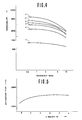
- Fig.4 shows frequency characteristics of magnetic permeability of the O-containing Fe-Al-Si alloy thin film. In this figure, the curve a represents the frequency characteristics for O contents of 0 weight percent, the curve b those for O contents of 0.3 weight percent, the curve c those for O contents of 1.0 weight percent, the curve d those for O contents of 2.4 weight percent, the curve e those for O contents of 3.8 weight percent and the curve f those for O contents of 4.9 weight percent.
- It is seen from Fig.4 that the Fe-Al-Si alloy thin film with O contents exhibits a higher magnetic permeability in any frequency than that without O contents. Above all, it may be appreciated that decrease in magnetic permeability in the higher frequency tends to be reduced with increase in the O contents. For example, the alloy thin film with O contents of 4.9 weight percent may be sufficiently employed in the frequency range of 20 to 30 MHz, although it exhibits a low magnetic permeability in the frequency region less than 10 MHz.
- In the characteristic diagram of Fig.5, there is shown the relation between the saturation magnetic flux density and the O contents of the Fe-Al-Si alloy thin film.
- In connection with the figure, it is of interest that the saturation magnetic flux density of the Fe-Al-Si alloy thin film is increased by the addition of O into the film. This may be highly meritorious in consideration that the saturation magnetic flux density is generally lowered by using additives aimed to improve hardness or temperature characteristics of the magnetic permeability. In the present Example, not only the reduction in the saturation magnetic flux density is prevented, but the saturation magnetic flux density is improved.
- It is seen from these results that the Fe-Al-Si alloy thin film is not only superior in hardness, rust-proofness or durability but also superior in magnetic characteristics such as permeability or saturation magnetic flux density and hence may be advantageously used e.g. in conjunction with magnetic heads.
- A composite target consiting of pure iron targets on which were placed Al and Si, or a composite target consisting of Fe₈₂ Al₇ Si₁₁ targets on which were placed Fe, Al and Si, were used as target, and the sputtering operation was carried out in an O₂- containing Ar gas and an O₂-free Ar gas, while the number of Al and Si targets or Fe, Al and Si targets was changed, for the preparation of the Fe-Al-Si alloy thin film of various compositions (with thickness of about 5 µm).
- The resulting Fe-Al-Si alloy thin film was heat-treated at 350° C to 800° C for 1-5 hours. Then, magnetic permeability of the film was measured with the aid of a permiance meter and the Vickers hardness was also measured with weighting of 50g. The composition of the resulting Fe-Al-Si alloy thin film was analyzed as to Fe, Al and Si contents with the aid of an X-ray micro-analyzer. The oxygen contents were measured by the gas analysis of the magnetic thin film formed on the Ni substrate. The results are shown in Table 1.
TABLE 1 composition (wt.%) permeability Vickers hardness Fe Al Si O 1MHz 5MHz comp. sample 194.8 2.1 3.1 0 260 220 580 sample 1 (94.8 2.1 3.1) x0.978 2.2 360 310 690 comp. sample 291.6 2.6 5.8 0 390 330 650 sample 2 (91.6 2.6 5.8) x0.978 2.2 460 400 780 comp. sample 387.1 9.8 3.3 0 280 240 620 sample 3 (87.1 9.8 3.3) x0.978 2.2 390 320 750 comp. sample 485.1 5.6 9.3 0 2300 1820 660 sample 4 (85.1 5.6 9.3) x0.978 2.2 4320 2880 860 comp. sample 582.4 8.2 9.4 0 1550 1450 770 sample 5 (82.4 8.2 9.4) x0.978 2.2 1720 1030 870 comp. sample 6 80.4 8.7 10.9 0 270 200 590 sample 6 (80.4 8.7 10.9) x0.978 2.2 1580 1310 950 comp. sample 7 86.3 2.4 11.3 0 380 330 700 sample 7 (86.3 2.4 11.3) x0.978 2.2 490 470 980 comp. sample 8 78.1 8.2 13.7 0 110 90 640 sample 8 (78.1 8.2 13.7) x0.978 2.2 640 600 960 comp. sample 9 78.7 6.3 15.0 0 100 70 800 sample 9 (78.7 6.3 15.0) x0.978 2.2 650 600 1050 comp. sample 1074.6 9.7 15.7 0 50 45 780 sample 10 (74.6 9.7 15.7) x0.978 2.2 260 240 1010 - It is seen from the above Table that the
samples 1 to 10 with O contents of 2.2 weight percent exhibit magnetic permeability higher than that of the O-free comparative samples and that,from the permeability values above all for 1 MHz and 5 MHz, the frequency characteristics are also improved. Likewise, it is seen that the Vickers hardness is also improved by ca. 200 to 300. - A composite target consisting of a pure iron target on which Al, Si and Co or Ni were mounted was used as target and the sputtering operation was carried out in an O₂-containing Ar gas and in an O₂-free Ar gas for the preparation of the Fe-Al-Si alloy thin film.
- The saturation magetic flux density, permeability and the Vickers hardness of the resulting Fe-Al-Si alloy thin film were measured. The results are shown in Table 2 below.
TABLE 2 composition (wt.%) permeability Vickers hardness saturation magnetic flux density (gauss) Fe Al Si Co or Ni O 1MHz 5MHz comp. sample 11 76.6 5.5 9.5 Co8.4 - 1260 840 680 12000 sample 11 (76.6 5.5 9.5 Co8.4) x0.978 2.2 2640 2090 850 12000 comp. sample 12 87.2 3.8 5.9 Ni3.1 - 1120 760 640 11000 sample 12 (87.2 3.8 5.9 Ni3.1) x0.978 2.2 2240 1830 760 11000 - It is seen from Table 2 that the Vickers hardness as well as magnetic permeability of the samples 11 and 12 with O contents of 2.2 weight percent were improved over those of the O-free comparative samples 11 and 12, while the saturation magnetic flux density of the samples 11 and 12 were not inferior to that of the comparative samples 11 and 12.
- Silicion (Si) with the purity of 99.9999 percent, aluminum (Al) with the purity of 99.99 percent and iron (Fe) with the purity of 99.99 percent were used as the starting materials. These starting materials were separately prepared in such weight amounts as to give a predetermined relative composition. The resulting batch was smelted in vacuum by using a high frequency smelting oven. The resulting molten product was poured into a mold for the preparaton of the alloy target.
- On this alloy target as reference were placed such elements as Fe, Al, Si and other additive elements,and the overall unit was charged into a high frequency sputtering unit, where sputtering was carried out in a Ar gas atmosphere containing oxygen gas O₂ for the magnetic thin film about 5 µm thickness.
- After heat-treatment at 350 to 800° C for 1 to 5 hours, magnetic permeability as well as the Vickers hardness of the resulting magnetic thin film was measured. The results are shown in Table 3. Measurement of magnetic permeability was effected with the aid of a permiance meter, while measurement of the Vickers hardness was effected with weighting of 50g for 15 seconds. The metal components of the resulting magnetic thin film were analyzed with an X-ray micro-analyzer and the O contents were determined by the gas analysis of the magnetic thin film simultaneously formed on the Ni substrate.

- It is seen from Table 3 that magnetic permeability as well as the Vickers hardness of the oxygen-containing magnetic thin film is markedly improved over those of the oxygen-free magnetic thin film.
- The saturation magnetic flux density and the coercive force were also measured in the above Examples and comparative Examples and were found to be substantially unchanged no matter whether or not oxygen was contained in the film samples. For example, while the saturation magnetic flux density and the coercive force of the comparative sample 13 amount to 1.1 T (11000 gauss) and 24 A/m (0.3 oersted), respectively, the saturation magnetic flux density of the sample 13 amounts to 1.1 T (11000 gauss) and the coercive force of the same sample amounts to 24 A/m (0.3 oersted).
- It will be appreciated from the foregoing that the present invention allows to provide a magnetic thin film high in hardness and superior in magnetic properties.
Claims (13)
- A magnetic thin film having a composition represented by the following formula:

wherein T is at least one element selected from the group consisting of IIIa group elements, IVa group elements, Va group elements, VIIa group elements, Ib group elements, Ga, In, Ge, Sn and Sb, P is at least one of platinum group elements, a, b, c, d, e and f each represents a weight percent of the respective element and satisfies the following relation


with a+b+c+d+e+f= 100, wherein the oxygen is uniformly distributed in said magnetic thin film. - The magnetic thin film as claimed in claim 1, characterized in that said IIIa group element is Sc, Y, La, Ce, Nd or Gd.
- The magnetic thin film as claimed in claim 1, characterized in that said IVa group element is Ti, Zr or Hf.
- The magnetic thin film as claimed in claim 1, characterized in that said Va group element is V, Nb or Ta.
- The magnetic thin film as claimed in claim 1, characterized in that said VIa group element is Cr, Mo or W.
- The magnetic thin film as claimed in claim 1, characterized in that said VIIa group element is Mn, Tc or Re.
- The magnetic thin film as claimed in claim 1, characterized in that said Ib group element is Cu, Ag or Au.
- The magnetic thin film as claimed in claim 1, characterized in that said platinum group element is Ru, Rh, Pd, Os, Ir or Pt.
- The magnetic thin film as claimed in claim 1, characterized in that said e and f satisfy the relation of e + f = 20 when Ru, Rh or Pd is used for platinum group elements.
- The magnetic thin film as claimed in claim 1, characterized in that said e and f satisfy the relation of e + f = 40 when Os, Ir or Pt is used for platinum group elements.
- The magnetic thin film as claimed in one of the claims 1 to 10, characterized in that a part of Fe is substituted by Co or Ni.
- The magnetic thin film as claimed in claim 11, characterized in that the relation of substitution by Co is in the range of 0 to 60 weight percent related to Fe.
- The magnetic thin film as claimed in claim 11, characterized in that the ratio of substitution by Ni is in the range of 0 to 40 weight percent related to Fe.
Applications Claiming Priority (2)
| Application Number | Priority Date | Filing Date | Title |
|---|---|---|---|
| JP76435/84 | 1984-04-18 | ||
| JP59076435A JPS60220914A (en) | 1984-04-18 | 1984-04-18 | Magnetic thin film |
Publications (3)
| Publication Number | Publication Date |
|---|---|
| EP0159028A2 EP0159028A2 (en) | 1985-10-23 |
| EP0159028A3 EP0159028A3 (en) | 1986-11-20 |
| EP0159028B1 true EP0159028B1 (en) | 1992-07-29 |
Family
ID=13605069
Family Applications (1)
| Application Number | Title | Priority Date | Filing Date |
|---|---|---|---|
| EP85104637A Expired - Lifetime EP0159028B1 (en) | 1984-04-18 | 1985-04-17 | Magnetic thin film |
Country Status (6)
| Country | Link |
|---|---|
| US (1) | US4671828A (en) |
| EP (1) | EP0159028B1 (en) |
| JP (1) | JPS60220914A (en) |
| KR (1) | KR930002396B1 (en) |
| CA (1) | CA1255890A (en) |
| DE (1) | DE3586404T2 (en) |
Families Citing this family (15)
| Publication number | Priority date | Publication date | Assignee | Title |
|---|---|---|---|---|
| DE3465661D1 (en) * | 1983-11-02 | 1987-10-01 | Hitachi Ltd | Ferromagnetic material, ferromagnetic laminate and magnetic head |
| US4735865A (en) * | 1985-06-10 | 1988-04-05 | Sharp Kabushiki Kaisha | Magnetic head core |
| JPH0777008B2 (en) * | 1985-06-21 | 1995-08-16 | 株式会社日立製作所 | Magnetic head using amorphous alloy film |
| JPS62188206A (en) * | 1985-10-07 | 1987-08-17 | Nippon Mining Co Ltd | Fe-si-al alloy magnetic film, manufacture thereof and thin film laminated magnetic head |
| JPS6285413A (en) * | 1985-10-11 | 1987-04-18 | Hitachi Ltd | Ferromagnetic multilayer film and its manufacturing method |
| US5038242A (en) * | 1988-05-13 | 1991-08-06 | Citizen Watch Co., Ltd. | Magnetic head containing a barrier layer |
| JPH088169B2 (en) * | 1989-09-12 | 1996-01-29 | 株式会社ジャパンエナジー | Method for producing Fe-Si-Al alloy magnetic thin film |
| JPH03111528A (en) * | 1989-09-26 | 1991-05-13 | Toshiba Corp | Magnetic alloy |
| EP0531514B1 (en) * | 1991-03-25 | 1996-08-28 | Eastman Kodak Company | A magnetic head for high-frequency, high-density recording |
| US5230818A (en) * | 1991-12-20 | 1993-07-27 | Eastman Kodak Company | Coating compositions for master media for anhysteretic recording |
| KR0160751B1 (en) * | 1993-01-15 | 1999-01-15 | 제프리 엘.포먼 | Magnetic laminated structure and method of manufacturing the same |
| JPH07210856A (en) * | 1994-01-19 | 1995-08-11 | Tdk Corp | Magnetic recording medium |
| JP2005223177A (en) * | 2004-02-06 | 2005-08-18 | Tdk Corp | Process for forming magnetic film, process for forming magnetic pattern, and process for producing magnetic recording medium |
| JP4319060B2 (en) * | 2004-02-13 | 2009-08-26 | Tdk株式会社 | Magnetic film forming method, magnetic pattern forming method, and magnetic recording medium manufacturing method |
| JP4319059B2 (en) * | 2004-02-13 | 2009-08-26 | Tdk株式会社 | Magnetic film forming method, magnetic pattern forming method, and magnetic recording medium manufacturing method |
Family Cites Families (11)
| Publication number | Priority date | Publication date | Assignee | Title |
|---|---|---|---|---|
| US3089795A (en) * | 1959-11-18 | 1963-05-14 | Westinghouse Electric Corp | Method for producing fiber texture and cube-texture sheets of iron-base alloys |
| US3965463A (en) * | 1972-08-29 | 1976-06-22 | International Business Machines Corporation | Apparatus using amorphous magnetic compositions |
| US4065330A (en) * | 1974-09-26 | 1977-12-27 | The Foundation: The Research Institute Of Electric And Magnetic Alloys | Wear-resistant high-permeability alloy |
| US4177089A (en) * | 1976-04-27 | 1979-12-04 | The Arnold Engineering Company | Magnetic particles and compacts thereof |
| JPS53119723A (en) * | 1977-03-30 | 1978-10-19 | Hitachi Metals Ltd | Method of making abrassionnresistant high permeability alloy |
| JPS5562145A (en) * | 1978-10-31 | 1980-05-10 | Hitachi Metals Ltd | Corrosion resistant, high permeability alloy |
| JPS5585656A (en) * | 1978-12-22 | 1980-06-27 | Hitachi Denshi Ltd | Wear-resistant high-permeability alloy, heat treating method therefor and magnetic head using said alloy |
| JPS55125258A (en) * | 1979-03-22 | 1980-09-26 | Kobe Steel Ltd | High permeability alloy with superior workability |
| JPS55152155A (en) * | 1979-05-16 | 1980-11-27 | Sumitomo Special Metals Co Ltd | Fine crystalline strip material for high permeability magnetic material, preparation and product thereof |
| JPS597334B2 (en) * | 1979-09-03 | 1984-02-17 | 株式会社神戸製鋼所 | Manufacturing method of Sendust alloy with excellent corrosion resistance |
| JPS5644755A (en) * | 1979-09-20 | 1981-04-24 | Hitachi Metals Ltd | Alloy of high magnetic permeability |
-
1984
- 1984-04-18 JP JP59076435A patent/JPS60220914A/en not_active Expired - Lifetime
-
1985
- 1985-04-03 CA CA000478279A patent/CA1255890A/en not_active Expired
- 1985-04-05 US US06/720,341 patent/US4671828A/en not_active Expired - Lifetime
- 1985-04-17 DE DE8585104637T patent/DE3586404T2/en not_active Expired - Fee Related
- 1985-04-17 KR KR1019850002585A patent/KR930002396B1/en not_active Expired - Lifetime
- 1985-04-17 EP EP85104637A patent/EP0159028B1/en not_active Expired - Lifetime
Also Published As
| Publication number | Publication date |
|---|---|
| EP0159028A3 (en) | 1986-11-20 |
| US4671828A (en) | 1987-06-09 |
| JPS60220914A (en) | 1985-11-05 |
| DE3586404D1 (en) | 1992-09-03 |
| KR850007510A (en) | 1985-12-04 |
| DE3586404T2 (en) | 1993-03-11 |
| CA1255890A (en) | 1989-06-20 |
| EP0159028A2 (en) | 1985-10-23 |
| KR930002396B1 (en) | 1993-03-30 |
Similar Documents
| Publication | Publication Date | Title |
|---|---|---|
| EP0159027B1 (en) | Magnetic thin film | |
| US4671828A (en) | Magnetic thin film | |
| US4969962A (en) | Magnetic alloys for magnetic head | |
| US5478416A (en) | Magnetic alloy | |
| US4298381A (en) | Abrasion-resistive high permeability magnetic alloy | |
| EP0178634B1 (en) | Amorphous soft magnetic thin film | |
| US5786103A (en) | Soft magnetic film and magnetic head employing same | |
| JPH0744107B2 (en) | Soft magnetic thin film | |
| JP2675178B2 (en) | Soft magnetic alloy film | |
| JP2996553B2 (en) | Soft magnetic alloy thin film | |
| KR960012244B1 (en) | Soft magnetic alloy film | |
| JP2668590B2 (en) | Magnetic alloy for magnetic head | |
| JP2508462B2 (en) | Soft magnetic thin film | |
| JP2546275B2 (en) | Soft magnetic thin film | |
| JPH0746654B2 (en) | Soft magnetic thin film | |
| JP3087265B2 (en) | Magnetic alloy | |
| JPH088169B2 (en) | Method for producing Fe-Si-Al alloy magnetic thin film | |
| JP3181723B2 (en) | Soft magnetic alloy film | |
| JP2569828B2 (en) | Magnetic alloys for magnetic devices | |
| JPS62104107A (en) | Soft magnetic thin film | |
| JPH07116564B2 (en) | Magnetic alloy | |
| JPH0546922A (en) | Soft magnetic alloy and magnetic head using the same | |
| JPH0789527B2 (en) | Crystalline soft magnetic thin film | |
| JPS59145760A (en) | Free cutting alloy with high magnetic permeability | |
| JPH0746656B2 (en) | Crystalline soft magnetic thin film |
Legal Events
| Date | Code | Title | Description |
|---|---|---|---|
| PUAI | Public reference made under article 153(3) epc to a published international application that has entered the european phase |
Free format text: ORIGINAL CODE: 0009012 |
|
| AK | Designated contracting states |
Designated state(s): DE FR GB NL |
|
| PUAL | Search report despatched |
Free format text: ORIGINAL CODE: 0009013 |
|
| AK | Designated contracting states |
Kind code of ref document: A3 Designated state(s): DE FR GB NL |
|
| 17P | Request for examination filed |
Effective date: 19870515 |
|
| 17Q | First examination report despatched |
Effective date: 19900117 |
|
| GRAA | (expected) grant |
Free format text: ORIGINAL CODE: 0009210 |
|
| AK | Designated contracting states |
Kind code of ref document: B1 Designated state(s): DE FR GB NL |
|
| REF | Corresponds to: |
Ref document number: 3586404 Country of ref document: DE Date of ref document: 19920903 |
|
| ET | Fr: translation filed | ||
| PLBE | No opposition filed within time limit |
Free format text: ORIGINAL CODE: 0009261 |
|
| STAA | Information on the status of an ep patent application or granted ep patent |
Free format text: STATUS: NO OPPOSITION FILED WITHIN TIME LIMIT |
|
| 26N | No opposition filed | ||
| REG | Reference to a national code |
Ref country code: GB Ref legal event code: IF02 |
|
| PGFP | Annual fee paid to national office [announced via postgrant information from national office to epo] |
Ref country code: FR Payment date: 20030408 Year of fee payment: 19 |
|
| PGFP | Annual fee paid to national office [announced via postgrant information from national office to epo] |
Ref country code: GB Payment date: 20030416 Year of fee payment: 19 |
|
| PGFP | Annual fee paid to national office [announced via postgrant information from national office to epo] |
Ref country code: DE Payment date: 20030424 Year of fee payment: 19 |
|
| PGFP | Annual fee paid to national office [announced via postgrant information from national office to epo] |
Ref country code: NL Payment date: 20030429 Year of fee payment: 19 |
|
| PG25 | Lapsed in a contracting state [announced via postgrant information from national office to epo] |
Ref country code: GB Free format text: LAPSE BECAUSE OF NON-PAYMENT OF DUE FEES Effective date: 20040417 |
|
| PG25 | Lapsed in a contracting state [announced via postgrant information from national office to epo] |
Ref country code: NL Free format text: LAPSE BECAUSE OF NON-PAYMENT OF DUE FEES Effective date: 20041101 |
|
| PG25 | Lapsed in a contracting state [announced via postgrant information from national office to epo] |
Ref country code: DE Free format text: LAPSE BECAUSE OF NON-PAYMENT OF DUE FEES Effective date: 20041103 |
|
| GBPC | Gb: european patent ceased through non-payment of renewal fee |
Effective date: 20040417 |
|
| PG25 | Lapsed in a contracting state [announced via postgrant information from national office to epo] |
Ref country code: FR Free format text: LAPSE BECAUSE OF NON-PAYMENT OF DUE FEES Effective date: 20041231 |
|
| NLV4 | Nl: lapsed or anulled due to non-payment of the annual fee |
Effective date: 20041101 |
|
| REG | Reference to a national code |
Ref country code: FR Ref legal event code: ST |