EP0158456A2 - Industrial lift truck with travel/lift inhibit control - Google Patents
Industrial lift truck with travel/lift inhibit control Download PDFInfo
- Publication number
- EP0158456A2 EP0158456A2 EP85301815A EP85301815A EP0158456A2 EP 0158456 A2 EP0158456 A2 EP 0158456A2 EP 85301815 A EP85301815 A EP 85301815A EP 85301815 A EP85301815 A EP 85301815A EP 0158456 A2 EP0158456 A2 EP 0158456A2
- Authority
- EP
- European Patent Office
- Prior art keywords
- lift
- signal
- speed
- height
- upright
- Prior art date
- Legal status (The legal status is an assumption and is not a legal conclusion. Google has not performed a legal analysis and makes no representation as to the accuracy of the status listed.)
- Withdrawn
Links
- 230000008878 coupling Effects 0.000 claims 1
- 238000010168 coupling process Methods 0.000 claims 1
- 238000005859 coupling reaction Methods 0.000 claims 1
- 239000003990 capacitor Substances 0.000 description 15
- 239000004020 conductor Substances 0.000 description 10
- 239000012530 fluid Substances 0.000 description 10
- 230000001105 regulatory effect Effects 0.000 description 10
- 238000004804 winding Methods 0.000 description 10
- 238000010586 diagram Methods 0.000 description 6
- 230000001052 transient effect Effects 0.000 description 6
- 230000001276 controlling effect Effects 0.000 description 2
- 230000006378 damage Effects 0.000 description 2
- 230000000694 effects Effects 0.000 description 2
- 230000007935 neutral effect Effects 0.000 description 2
- 239000007787 solid Substances 0.000 description 2
- 208000027418 Wounds and injury Diseases 0.000 description 1
- 230000003247 decreasing effect Effects 0.000 description 1
- 238000007599 discharging Methods 0.000 description 1
- 208000014674 injury Diseases 0.000 description 1
- 239000007788 liquid Substances 0.000 description 1
- 239000003381 stabilizer Substances 0.000 description 1
Images


Classifications
-
- B—PERFORMING OPERATIONS; TRANSPORTING
- B66—HOISTING; LIFTING; HAULING
- B66F—HOISTING, LIFTING, HAULING OR PUSHING, NOT OTHERWISE PROVIDED FOR, e.g. DEVICES WHICH APPLY A LIFTING OR PUSHING FORCE DIRECTLY TO THE SURFACE OF A LOAD
- B66F17/00—Safety devices, e.g. for limiting or indicating lifting force
- B66F17/003—Safety devices, e.g. for limiting or indicating lifting force for fork-lift trucks
Definitions
- This invention relates to industrial lift trucks and more particularly to an automatic control system for governing the lift function and the travel of the truck to enhance the safety of operation.
- a lift truck of the type known as an order-picker truck In certain types of industrial operations, such as warehousing, it is common practice to use a lift truck of the type known as an order-picker truck.
- Such trucks provide an extendible upright for a lift fork and an operator's station on the extendible upright. The operator controls the speed and steering of the truck and the lifting and lowering of the upright form this platform. It is desirable to provide safeguards against possible injury to the operator or damage to the vehicle in the event the operator attempts to operate or load the vehicle in an unsafe manner. In some of such vehicles, it is possible for the operator to manually control the elevation of the lift fork and loading in such a manner that the vehicle becomes unstable and may overturn in the event of excessive speed or turning the vehicle too sharply. ,
- United States Patent No. 3,486,333 describes a lift truck with a manually controlled extendible upright and an automatic system for preventing extension of the upright at high speed above a predetermined height.
- the automatic control system of this patent utilizes a limit switch located on the upright for disabling the high speed lift operation at a predetermined height. Above this height, only low speed lift operation is available.
- United States Patent No. 3,524,522 describes a lift truck with an extendible upright and means for limiting the speed of operation of the truck as a function of the height of the upright.
- a speed control device of the solid state type for varying the speed of the traction motor by varying the duration of power pulses or the frequency of power pulses from a battery to the motor.
- the current to the motor control device which varies the duration or frequency of the power pulses, is controlled by first and second variable resistors in series with a normally closed limit switch, the vehicle battery and a control input of the speed control device.
- the first variable resistor is actuated by the manual accelerator lever and has a maximum resistance in the normal or low speed position.
- the second variable resistor is actuated by a float in the hydraulic reservoir of the lift system so that it has a maximum resistance with the extendible upright at its maximum height.
- the maximum speed at which the motor can be operated is no greater than the speed called for by the setting of either variable resistor, whichever is lower. More particularly, speed can be no greater than the value corresponding to,the sum of the resistances of the two variable resistors.
- a general object of this invention is to provide an improved automatic speed and lift control for safeguarding the operation of an industrial lift truck.
- the present invention provides a lift truck of the type comprising an electric traction motor, manually controlled signal generating means for generating a speed command signal voltage corresponding to a desired speed, an extendible upright, and control means for said motor responsive to the speed control voltage for controlling the speed of said motor, comprising: signal generating means operatively coupled with said upright for generating a height signal voltage corresponding to the amount of extension of said upright, logic means responsive to said speed command signal voltage and to said height signal voltage for producing a speed control voltage correspondng to the value of the larger of said signal voltages, and means for applying said speed control voltage to said control means whereby the speed of said motor is governed by only on of said signal voltages.
- the electronic control system is responsive to the signal corresponding to the height of the upright to exercise one or more of the following controls: interrupt vehicle travel if the steering angle is excessive; limit the speed of the vehicle in accordance with the height of the upright; cut-off the high speed lift when the upright reaches a predetermined height; disable the lowering of the upright at a predetermined limit and permit a manual override and interrupt the high speed lowering of the upright at a predetermined height and permit manual override.
- the electronic control circuit is adapted to provide an overload warning when there is an excessive load on the lift fork and the lift and lower switches are open; disable the lowering function of the upright in the event that the load forks engage an obstacle during lowering, and disable the lifting function in the event that the vehicle battery voltage is below a predetermined value.
- the lift truck 10 includes a body 12 supported by a drive-steer wheel 14 and a pair of tandem outrigger wheels 16 on each side.
- the drive-steer wheel 14 serves not only as the traction wheel for driving the vehicle but also as the dirigible wheel for steering the vehicle.
- a stabilizer wheel 18 is attached to each side of the body 12.
- a drive unit 22 ( Figure 3) for driving the drive-steer wheel 14 is mounted on the body and includes an electric traction motor 24 (see Figure 5).
- a telescopic upright 26 is also mounted on the body 12 and is powered by a piston and cylinder type single acting fluid lift motor 28 (see figure 4).
- a load engaging fork including a pair of fork arms 32 and an operator's station 34 are mounted for movement with extendible upright.
- the operator's station 34 includes a platform 36 on which the operator stands during operation of the lift truck.
- the operator's station 34 is provided with a control panel which includes a direction and speed control handle 38.
- the control panel is also provided with a lift/lower control lever 42 which allows the operator to manually control the energization of the extendible upright for low speed or high speed lift and for low speed and high speed lower.
- a steering tiller 44 is provided for manual control of the drive-steer wheel 14.
- a direction indicator 46 is provided on the control panel for indicating the steering angle to the operator.
- a hydraulic sump tank 48 is mounted on the body 12 under a hood 20.
- the sump tank is provided with a height sensor 52 comprising a float actuated potentiometer.
- the liquid level in the sump tank 48 corresponds to the height of the extendible upright 26 and the height sensor 52 produces a signal voltage corresponding to the height.
- a low speed lift pump 54 positioned under the hood, as shown in Figure 3, are a low speed lift pump 54, a high speed lift pump 56 and a lowering control valve 58.
- a steering angle sensor 62 is belt driven by the drive unit 22 and develops an electrical signal voltage corresponding to steering angle.
- an overload warning horn 64 is also, located under the hood.
- the hydraulic system for extending and retracting the upright 26 of the lift truck is shown in Figure 4.
- the fluid motor 28 is energized by the lower speed pump 54.
- the pump 54 has its intlet connected with the sump tank 48 and its outlet connected through a check valve 68 and a flow control valve 72 to the inlet motor 28.
- the flow control valve 72 provides substantially unrestricted flow into the motor 28 and regulates the flow out of the motor depending upon the load carried by the upright 26, i.e., the restriction to flow increases with increased load.
- the motor 28 is energized by both the low speed pump 54 and the high speed pump 56 which, with a check valve 69 is connected in parallel with the pump 54.
- a solenoid actuated, normally open, dump valve 118 is connected between the outlets of the pumps 54 and 56 and the sump tank 48.
- the lowering operation of the upright 26 is provided by controlled flow of hydraulic fluid from the motor 28 back to the sump tank 48.
- the outlet of the fluid motor 28 is connected through the flow control valve 72, a solenoid operated low speed lowering valve 74 and a flow restrictor 75 to the sump tank 48.
- the pumps 54 and 56 are deenergized and the low speed lowering valve 74 is opened.
- the flow of fluid from the motor 28 is restricted by the valve 74 and additionally it is restricted by the flow restrictor 75 so that the upright is lowered at a slow speed.
- a high speed lowering control valve 76 is connected between the valve 72 and the sump tank 48.
- the pumps 54 and 56 are deenergized, low speed lowering valve 74 remains closed and the high speed lowering control valve 76 is opened. This provides less restriction to the flow from the motor 28 and the upright is lowered at high speed.
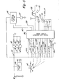
- FIG. 5 A block diagram of the electrical control system for the lift truck in shown in Figure 5.
- the vehicle and the control circuits are powered from a storage battery 82.
- the centrol system comprises a travel-lift interrupt circuit board 84 which receives manual control and sensor input signals and develops output control signals for the traction motor 24 and the lift-lower control system for the extendible upright.
- a voltage regulator 86 is connected across the battery 82 and develops regulated voltage at values of 12 volts, 10 volts and 5 volts for supply voltages to the electronic control circuits in the circuit board 84.
- a speed and direction control circuit 88 of the solid state, pulse/duration type, is connected between the battery 82 and the traction motor 24.
- a power steering motor 92 is connected through a control contactor 94 across the battery 82.
- a low speed lift pump motor 96 is connected through a contactor 98 across the battery 82 and a high speed lift pump motor 102 is connected through a contactor 104 across the battery 82.
- the travel-lift interrupt circuit board 84 is provided with a plurality of manually controlled inputs and sensor inputs for the purpose of developing output control signals, as will be discussed presently.
- a manually controlled lift/lower override switch 352 is connected directly between the battery and the input of the circuit board 84.
- the lift/lower control lever 42 is manually actuable from a neutral position in a counterclockwise direction to select low speed lift at position LS and to select high speed lift at the position HS.
- the lower 42 is actuable in the clockwise direction to select low speed lower at the position LS and to select high speed lower at the position HS.
- the control lever is operably connected by a suitable cam arrangement to actuate the lift control switches 434, 484, 294 and 374.
- the lift control switch 434 is the low speed lift switch and is connected between the battery and an input of the circuit board 84.
- the solenoid winding 116 of the dump valve 118 and the pump contactor winding 122 for low speed lift pump 54 are connected in parallel between the switch 434 and an input of the circuit board 84.
- the lift control switch 484 is the high speed lift switch and it is connected between the battery 82 and an input of the circuit board 84.
- a pump contactor winding 124 for the high speed pump motor 102 is connected between the switch 484 and an input of the circuit board 84.
- the lowering control switch 294 is the low speed lowering switch and is connected between the battery 82 and the circuit board 84.
- a solenoid 312 of the low speed lower solenoid valve 74 is directly connected between the battery 82 and an input of the circuit board 84 and similarly solenoid 392 of the high speed lowering solenoid valve 76 is connected directly between the battery 82 and the circuit board 84.
- the lowering control switch 374 is the high speed lowering switch and is connected between the battery 82 and an input of the circuit board 84.
- a load sensing pressure switch 564 is connected between the battery 82 and an input of the circuit board 84. Switch 564 is normally open and is adatped to close in response to a predetermined high pressure in the fluid motor 28.
- a no-slack switch 414 is connected between the battery 82 and an input of the circuit board 84.
- the no-slack switch 414 is responsive to the slack or no-slack condition of the lift chain of the extendible upright which is actuated by the fluid motor 28.
- the drive chain When the upright is being lifted or lowered, either with or without load, the drive chain should operate with no-slack. However, during a lowering operation, if the load fork should engage an obstacle, such as a storage bin, then the chain will become slack. This condition is sensed by the no-slack switch, the switch being closed when the chain is tight and being opened when the chain is slack.
- the overload warning horn 64 is connoted directly between the battery 82 and an input of the circuit board 84.
- a battery condition sensor 136 which senses the voltage of the battery 82 is connected between the battery and ground and has an output connected to an input of the circuit board 84.
- the direction and speed control handle 38 includes a potentiometer 138 for producing a speed command signal voltage.
- the potentiometer 138 suitably comprises a fixed resistor connected across the regulated 5 volt source and having its wiper contact connected with an input of the circuit board 84.
- the potentiometer is adapted to produce a speed command signal voltage which varies inversely with the desired speed, i.e. the signal voltage is high for creep speed and it is low for high speed.
- a speed control voltage is developed by the circuit board 84 and applied through a conductor 142 to the control input of the speed and direction control circuit 88.
- the steering angle sensor 62 suitably takes the form of a potentiometer 66 and is connected across terminals of the circuit board 84 for receiving a regulated voltage thereacross.
- the tap of the potentiometer is positioned in accordance with the direction angle of the drive/steer wheel of the truck and develops a signal voltage corresponding in polarity and magnitude with the direction and angle of the drive/steer wheel from the straight ahead direction.
- the tap of the potentiometer 62 is applied to an input of the circuit board 84.
- the height sensor 52 also includes a potentiometer 144 connected across terminals of the circuit board 84 which apply a regulated voltage thereacross.
- the movable tap of the potentiometer 144 develops a height signal voltage corresponding to the height of the extendible upright of the lift truck and is connected to an input terminal of the circuit board 84.
- the circuit board 84 will be described presently.
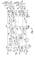
- the circuit board 84 comprises a speed control channel and travel interrupt channel, as shown in Figure 6, a lower control channel and obstruction interrupt circuit as shown in Figure 7, a lift control channel and battery condition detecting circuit as shown in Figure 8, and an overload warning circuit as shown in Figure 9. These circuits, which make up the circuit board 84, will now be described in detail.
- This channel receives, as input, the speed command signal from the potentiometer 138 which, as discussed previously, is actuated by the manual direction and speed control handle 38.
- This channel also receives, as input, the height signal from the potentiometer 144 of the height sensor 52.
- the speed control channel 152 comprises a signal selector circuit 154 and a speed signal amplifying circuit 156.
- the speed command signal on the wiper contact of the potentiometer 138 is applied through a resistor 158 to the noninverting input of an operational amplifier 162 in the amplifying circuit 156.
- the speed command signal is also applied through the resistor 158 to the inverting input of an - operational amplifier 164 which functions as a reference switching comparator, as will be discussed presently.
- the height signal from the potentiometer 144 is applied through an input filter comprising a series resistor 166 and shunt capacitor 168 to the noninverting input of an operational amplifier 172 which is connected to function as a unity gain, impedence matching amplifier.
- the output of the operational amplifier 172 is the height signal and is applied across the diode 174 and a resistor 176 which functions as a noise supression circuit.
- the voltage at the node between the diode 174 and resistor 176 is applied across a voltage divider comprising a variable resistor 178 and fixed resistors 182 and 184.
- the voltage at the node between resistors 182 and 184 is applied to the noninverting input of the operational amplifier 164.
- the output of the operational amplifier is connected through a diode 186 to the noninverting input of the operational amplifier 162.
- the operational amplifier 164 functions in such a manner that a speed control signal is applied to the noninverting input of the operational amplifier 162, the speed control signal being either the speed command signal or modified height signal whichever is greater, as will be described presently.
- the speed signal amplifying circuit 156 comprises the operational amplifier 162 which receives the speed control signal on its noninverting input. It also comprises a power amplifier including transistors 188 and 192.
- the output of the operational amplifier 162 is applied through a resistor 194 to the base of the transistor 188.
- the emitter of the transistor 188 is connected with the regulated 5 volt power supply and a diode 196 is connected between the base and emmiter.
- the collector of the tranistor 188 is connected through a resistor 198 to the base of the transistor 192.
- the collector of the transistor 192 is connected across an output resistor 202 and the emitter is connected to - ground.
- the collector of the transistor 192 is also connected to the inverting input of the operational amplifier 162.
- the operational amplifier 162 functions as a unity gain noninverting amplifier.
- the speed control signal is thus developed across the transistor 192, i.e. the voltage at the collector of the transistor 192 follows the voltage applied to the noninverting input of the operational amplifier 162.
- the speed control signal is applied to the control input of the speed and direction control circuit 88 on conductor 142, as discussed with reference to Figure 5.
- the operational amplifier 164 operates as a reference switching comparator such that the output thereof is applied to the noninverting input of the operational amplifier 162 only if the modified height signal at the noninverting input of amplifier 164 is greater than the speed command signal at the inverting input of the amplifier 164. In this case, the output of the amplifier 164 is applied through the diode 186 in the forward direction to the noninverting input of operational amplifier 162.
- the speed control signal at the noninverting input of amplifier 162 is either the speed signal from the potentiometer 138 or the modified height signal from the amplifier 164, whichever is greater. It is noted that the speed command signal from the potentiometer 138 varies inversely with the desired speed, i.e. the highest voltage corresponds to the lowest speed and the lowest voltage corresponds to the maximum speed. This operation is depicted in the graph of Figure 10.
- the ordinate represents the truck speed ranging from zero to maximum speed, say five miles per hour with creep speed at one mile per hour.
- the height of the extendible upright which is indicated as fork height above the floor, is shown as ranging from zero to 240 inches (610cm). For fork height up to 24 inches (6lcm) full speed of the truck is permitted.
- the speed command signal from the potentiometer 138 is greater than the modified height signal even when the operator actuates the direction and speed control lever to the maximum speed position which produces the lowest speed command signal.
- the modified height signal becomes greater than the speed command signal for full speed and accordingly, the output of the operational amplifier 164 corresponds to the modified height signal which is applied through the diode 186 to the noninverting input of the amplifier 162.
- the height signal prevails over the speed command signal to produce the speed control signal at the noninverting input of amplifier 162.
- This is applied to the speed signal amplifier circuit 156 to the speed and direction control circuit 88 and the decreased value of the speed control signal causes reduction in the truck speed.
- the truck speed increases as a function of fork height between the fork height of 24 inches (61cm) and the fork height of 180 inches (457cm).
- the slope of this portion of the graph is preset by the adjustment of the variable resistor 178. It can be seen from the graph that the speed control channel operates so that the maximum permitted speed of the truck is limited by the fork height. When the fork height reaches 180 inches (457cm), the truck is allowed to operate at creep speed only. The travel of the truck is further limited by the travel interrupt control channel which will be described presently.
- the travel interrupt control channel 212 will now be described with reference to Figure 6.
- this channel is operative to stop or interrupt the travel of the truck, whether it is in forward or reverse drive, when the driver turns the truck at too sharp an angle for the existing height of the load forks.
- the height at which travel is interrupted varies inversely with the steering angle.
- the travel interrupt control channel 212 comprises a comparator 214 which receives the height signal from the height sensor 52.
- a steering signal circuit 216 comprising a pair of comparators 218 and 222 develops a steering reference signal which is also applied to the comparator 214.
- the output of the comparator 214 controls a transistor 224 which develops a travel interrupt signal.
- the circuitry of the travel interrupt control channel 212 will now be described in greater detail.
- the height signal from the height sensor 52 is applied from the output of the amplifier 172 through a"conductor 226 and a resistor 228 to the noninverting input of the comparator 214.
- the inverting input of the comparator 214 is connected with a reference voltage source comprising a voltage divider 232.
- the voltage divider 232 develops a changeable reference voltage which changes in accordance with the steering angle of the truck.
- the voltage divider 232 is connected in the steering signal circuit 216 which will be described presently.
- the steering signal circuit 216 includes the steering angle sensor 62 which comprises a potentiometer 66.
- the steering angle sensor 62 is coupled with the drive-steer wheel 14 in such a manner that the movable contact of the potentiometer 66 is positioned at the midpoint of the resistor when the drive-steer wheel 14 is straight ahead. Accordingly, for a given gear ratio in the steering gear, the range of steering angle from the maximum angle for a right-hand turn to the maximum for a left-hand turn will cause the wiper contact to sweep a range of 360 degrees. With a supply voltage of 10 volts on the potentiometer 66, the steering angle signal would be 5 volts for straight ahead, 10 volts for maximum right-hand steering angle and 0 volts for maximum left-hand steering angle.
- the movable contact of the potentiometer 66 might sweep over a range of only 270 degrees.
- the steering angle signal would still be 5 volts for straight ahead but it would be a lesser voltage for maximum right-hand steering signal and a greater voltage for maximum left-hand steering signal.
- the steering signal from the steering sensor 62 is applied through a filter comprising a series resistor 234 and a shunt capacitor 236 to the noninverting input of a unity gain amplifier 238.
- the output of the amplifier 238 is applied through a resistor 242 to the steering signal indicator 46.
- the output of the amplifier 238 is also applied to the inverting input of the comparator 218 and to the noninverting input of the comparator 222.
- the comparator 218 is part of a reference switching circuit for establishing the steering angle limit for the right-hand turn and the comparator 222 is part of a reference switching circuit for establishing the limit for the left-hand steering angle.
- the noninverting input of the comparator 218 is connected through a resistor 244 to an adjustable contact on a voltage divider 246 which is connected across a source of reference voltage.
- the output of the comparator 218 is connected through a diode 248 and a resistor 252 to the noninverting input.
- the output is also connected through a diode 254 to the voltage divider 232.
- the voltage divider 232 comprises a fixed resistor 256, a potentiometer 258 and a fixed resistor 262 which are connected in series across a source of reference voltage.
- the movable contact of the . potentiometer 258 is connected with the inverting input of the comparator 214, as previously described.
- a fixed resistor 264 is connected through a closed switch 266 between the diode 254 and the junction of potentiometer 258 and resistor 262. When the output of the comparator 218 goes to logic low, the resistor 264 is effectively connected in parallel with the resistor 262 thus switching the value of the reference voltage on the potentiometer 258 from a higher value to a lower value.
- the resistor 264 is used in the circuit for a truck having a wide range of steering angles whereas the resistor 268 is used in the circuit for a truck having a narrower range of steering angles, the selection being made by switches 266 and 272.
- the comparator 222 of the reference switching circuit for establishing the limit of the left-hand steering angle has its inverting input connected with another adjustable contact of the voltage divider 246.
- the steering signal is applied from the amplifier 238 through resistor 245 to the noninverting input of the comparator 222.
- the output of the comparator 222 is connected through a diode 274 and a resistor 276 to the noninverting input.
- the output of the comparator 222 is connected through the diode 278 to the voltage divider 232, i.e. through the switch 266 and resistor 264.
- the resistor 264 is effectively connected across the resistor 262 thus switching the reference voltage produced by the voltage divider 232 from a higher value to a lower value.
- the comparator 214 receives the height signal voltage on its noninverting input and it receives the reference voltage from the voltage divider 232 on its inverting input.
- the output of the comparator 214 is connected through the diode 282 and a resistor 284 to the noninverting input.
- the output is also applied through a resistor 286 to the base of the transistor 224 which is connected to ground through a resistor 288.
- the emitter of the transistor 224 is connected to ground and the collector is connected through a conductor 289 to an input of the speed and direction control 88.
- the output of the transistor 224 is a travel interrupt signal which, when applied to the speed and direction control circuit 88, is effective to open the forward and reverse contactors thereby deenergizing the traction motor 24 to interrupt the travel of the truck.
- the operation of the travel interrupt control channel 212 will now be described.
- the height signal from the height sensor 52 is applied to the noninvertng input of the comparator 214, as previously described.
- the changeable reference voltage from the voltage divider 232 is applied to the inverting input of the comparator 214.
- the output of the comparator 214 is at logic low and the transistor 224 is turned off.
- the travel interrupt signal on conductor 289 is high and does not affect the travel of the truck.
- the steering angle signal applied to the input of the comparator 218 will be less than the reference input thereto and the steering angle signal at the input of comparator 222 will be greater than the reference input thereto. Accordingly, the ouputs of both comparators 218 and 222 will be at logic high and the voltage divider 232 will be unaffected by the comparators. Under this condition, the reference voltage at the inverting input of the comparator 214 will be relatively high. Accordingly, the height signal will be less than the reference signal until the load forks of the truck are raised to a first predetermined travel interrupt height. At that height, the height signal will exceed the reference signal and the output of the comparator 214 will go to logic high.
- the lowering control channel for the extendible upright is shown in Figure 7.
- This circuit includes manual control so that the operator can lower the load forks 32 at low speed or at high speed.
- automatic control is provided to interrupt lowering of the forks below a predetermined low speed interrupt height at log speed and to prevent lowering the forks below a predetermined high speed interrupt height at high speed.
- Manual override of the automatic control circuit is also provided. Additionally, this control circuit interrupts lowering at either high speed or low speed in the event that the forks encounter an obstacle.
- the lowering control channel includes a low speed lowering circuit 292 which, in general, comprises a manual low speed lowering switch 294, a fork height limit control circuit 296 and a driver stage 298 for the low speed lowering control valve 74.
- the manual switch 294 has one contact connected with the battery voltage and is normally opened.
- a filter capacitor 302 is connected between the other switch contact and ground.
- the switch is connected through a conductor 304 and a resistor 306 to the base of a Darlington transistor 308.
- the solenoid winding 312 of the low speed lower control valve 74 is connected to the collector of the transistor 308 and the emitter thereof is connected to ground.
- a varistor 314 is connected between the collector and ground for transient protection of the transistor.
- a switching transistor 316 is connected to the base of transistor 308 for automatic control purposes which will be described presently. Disregarding, for explanatory purposes, the effect of transistor 316, closing the manual switch 294 turns on the transistor 308 and actuates the low speed lower control valve 74.
- the fork height limit control circuit 296 includes the switching transistor 316.
- the fork height limit control circuit 296 is adapted to automatically stop the lowering of the load forks for handling certain types of loads when the low speed interrupt height is reached.
- it includes a reference voltage circuit comprising a voltage divider 318 connected across the regulated 10 volt source. It also comprises a unity gain amplifier 322 having its input connected with the voltage divider 318 and having its output connected across a potentiometer 324. The movable contact of the potentiometer 324 is positioned so that the voltage thereon corresponds to a predetermined height of the load forks above the floor, say 24 inches (61cm).
- the limit control circuit 296 comprises a comparator 326 which has its noninverting input connected through a resistor 328 to the potentiometer 324.
- the inverting input of the comparator 326 receives the height signal from the height sensor 52.
- the output of the comparator 326 is connected through a resistor 332 to the noninverting input.
- the output is also connected to the first input of a NAND gate 334.
- the second input of the NAND gate 334 is connected to a lift/lower override circuit 336 which will be described subsequently.
- the output of the NAND gate 334 is connected to the input of an inverter 338, the output of which is connected to the first input of a NOR gate 342.
- the output of the comparator 326 is also connected with the first input of a gate 344 which has its second input connected with the lift/lower override circuit 336.
- the gate 344 is an AND gate with inverting inputs.
- the output of the gate 344 is connected with the second input of the NOR gate 342.
- the output of the NOR gate 342 is connected through a diode 346 and a resistor 348 to the base of the switching transistor 316.
- This circuit is manually controlled and permits the operator to override the fork height limit control circuit 296 in such a manner that the load forks can be lowered below the low speed of interrupt height after they have been stopped at that limit position.
- This override circuit comprises a push button override switch 352 with one fixed contact connected to the regulated voltage source and the other fixed contact connected through a resistor 354 to the second input of the gate 344.
- a filter for the override circuit includes shunt capacitors 356 and 358 and a shunt resistor 362.
- the operation of the low speed lowering control circuit 292 is as follows. With the load forks 32 of the extendible upright 26 in an elevated position above the low speed interrupt height, the height signal is greater than the reference signal corresponding to the interrupt height.
- the logic state of the limit control circuit 296 is as follows. The height signal at the inverting input of comparator 326 is greater than the reference signal at the noninverting input and accordingly the output of the comparator is low. This causes the first input of the NAND gate 334 to be at logic low. The second input of the NAND gate 334 is low since the lift/lower override switch 352 is open.
- the output of the NAND gate 334 is high and the output of the inverter 338, and hence the first input of the NOR gate 342 is low.
- the second input of the NOR gate 342 is high since both the first and second inputs of the gate 344 are low. Accordingly, the output of the NOR gate 342 is low and thus the switching transistor 316 is turned off. In this state, the switching transistor 316 does not effect the transistor 308. Accordingly, when the operator closes the low speed lower switch 294 the transistor 308 is turned on and the solenoid winding 312 of the low speed lower valve 74 is energized. This allows the load forks 32 to descend at low speed as controlled by the valve 74 and the flow restrictor 75 (see Figure 4).
- the logic state of the limit control circuit 296 is as follows.
- the output of the comparator 326 is high; hence, the first input of the NAND gate 324 is high and the second input thereof remains low. Accordingly, the input of the inverter 338 is high and the first input of the NOR gate 342 is low.
- the second input of the NOR gate 342 is also low since the first input of the gate 344 is high and the second input thereof is low. Thus, the output of the NOR gate 342 is high and the switching transistor is turned on.
- the high speed lowering control circuit 372 comprises a manual high speed lowering switch 374, a fork height limit control circuit 376 and a driver stage 378.
- the manual switch 374 has one contact connected to the battery voltage and the other contact is connected with a filter capacitor 382 and the conductor 384 through a resistor 386 to the base of a Darlington transistor 388 in the driver stage 378.
- the collector of the Darlington transistor 388 is connected with the solenoid winding 392 of the high speed lowering control valve 76.
- the emitter of transistor 388 is connected to ground.
- a varistor 394 is connected between the collector and ground for transient protection.
- the fork height limit control circuit 376 comprises a comparator 396 and a switching transistor 398.
- the inverting input of the comparator 396 receives the height signal from the height sensor 52 and the noninverting input receives a reference voltage from the voltage divider 318 through the unity gain amplifier 322 and a resistor 402.
- the output of the comparator 396 is connected through a resistor 404 with the noninverting input.
- the output of the comparator 396 is also connected through a diode 406 and a resistor 408 to the base of the switching transistor 398.
- the operation of the high speed lowering control circuit 372 is as follows.
- the reference voltage applied to the comparator 396 is derived from the voltage divider 318 and establishes the high speed interrupt height. This reference voltage is, of course, higher than that applied to the comparator 326 in the low speed circuit so that the high speed limit circuit will stop the descent of the load forks 32 at say 36 inches (91cm) above the floor.
- the output of the comparator 396 is low. Accordingly, the switching transistor 398 is turned off.
- the load forks can be lowered at high speed by closing switch 374 which turns on the Darlington transistor 388 and energizes the solenoid winding 392 of the high speed lowering control valve 76.
- the load forks 32 descend to the high speed interrupt height, the height signal will become less than the reference signal and the output of the comparator 369 will go to logic high. This turns on the switching transistor 398 and thereby shorts the base of transistor 388 to ground.
- Transistor 388 is turned off and the high speed lowering control valve 76 is deenergized.
- the load forks 32 are automatically stopped at the high speed interrupt height.
- the operator may lower the forks from this height by closing the low speed lowering switch to cause the forks to be lowered at low speed under the control of the low speed lowering circuit 292, as described above.
- the obstruction interrupt circuit 412 is also shown in Figure 7.
- This circuit comprises an obstruction sensor in the form of a no-slack switch 414 which is normally closed but which is opened when the load forks 32 engage an obstacle during lowering of the forks.
- the switch 414 is actuated by the lift chain 415 (see Figure 1) when it becomes slack as a result of an obstruction.
- the switch 414 has one contact connected with the battery voltage while the other contact is connected with a filter circuit 416 and to an inverter 418.
- the output of the inverter 418 is connected through a diode 422 and a resistor 423 to the base of switching transistor 316.
- the base of the transistor 316 is connected through a resistor 424 to ground.
- the output of the inverter 418 is also connected through a diode 426 and a resistor 427 to the base of switching transistor 398.
- the base of transistor 398 is connected through a resistor 428 to ground.
- the operation of the obstruction interrupt circuit 412 is as follows.
- the switch 414 When the switch 414 is closed, the ouptut of the inverter 418 is low and the circuit does not affect either switching transistor 316 or switching transistor 398.
- the switch 414 when the switch 414 is opened the output of the inverter 418 goes high and this turns on the switching transistor 316 and the switching transistor 398.
- both the low speed lowering control valve 74 and the high seed lowering control valve 76 are prevented from being energized.
- whichever control valve 74 or 76 was energized at the time of engagement of obstruction, will be deenergized and the descent of the load forks is stopped.
- the lift control channel for the extendible upright is shown in Figure 8 and is similar to the lowering control channel previously described.
- This circuit includes manual control so that the operator can raise the load forks 32 at low speed or at high speed.
- Automatic control is provided to permit raising the forks at high speed up to above a high speed interrupt height and then to continue at low speed operation.
- the automatic control prevents raising the forks above preset lift interrupt height without manual override.
- Manual override of the automatic control circuit for the low speed operation is provided.
- this control channel includes a battery condition circuit which disables the lifting function in the event of low battery voltage.
- the lift control channel includes a low speed lift control circuit 432 which, in general, comprises a manual low speed lift switch 434, a fork height limit control circuit 436 and a driver stage 438 for the coil 122 of the contactor 98 of the low speed lift pump motor 96 and the solenoid winding 116 of the dump valve 118.
- the manual switch 434 has one contact connected with the battery voltage and is normally open.
- a filter capacitor 442 is connected between the other switch contact and ground.
- the switch is connected through a conductor 444 and a resistor 446 to the base of a Darlington transistor 448.
- the coil 122 and winding 116 are connected to the collector of the transistor 448 and the emitter thereof is connected to ground.
- a varistor 452 is connected between the collector and ground for transient protection.
- a switching transistor 454 is connected to the base of transistor 448 for automatic control purposes which will be described presently. If the switching transistor 454 is turned off, closing of the manual switch 434 turns on the transistor 448 and energizes the solenoid 116 and coil 122 which actuates the low speed lift pump motor and the dump valve.
- the fork height limit control circuit 436 includes the switching transistor 454. This control circuit is adapted to automatically interrupt the load forks when a predetermined lift interrupt height above the floor is reached. For this purpose, it includes a reference voltage circuit comprising a voltage divider 456 connected across the regulated 10 volt source. The movable contact of the voltage divider 456 is positioned so that the voltage thereon corresponds to the lift interrupt height of the load forks above the floor, say 190 inches (483cm).
- the limit control circuit 436 comprises a comparator 458 which has its inverting input connected to the voltage divider 456. The noninverting input of the comparator 458 is connected through a resistor 462 to the height sensor 52 and receives the height signal.
- the output of the comparator 458 is connected through a resistor 464 to its noninverting input.
- the output is also connected to the first input of a NAND gate 466.
- the second input of the NAND gate 466 is connected to the lift/lower override circuit 336 which was described previously.
- the output of the NAND gate 466 is connected through an inverter 468 to the first input of a NOR gate 472.
- the output of the comparator 458 is also connected to the first input of a gate 474 which has its second input connected with the override circuit 336.
- Gate 474 is an AND gate with inverted inputs.
- the output of the gate 474 is connected with the second input of the NOR gate 472.
- the output of the NOR gate 472 is connected through a diode 476 and a resistor 478 to the base of the switching transistor 454.
- the high speed lift control circuit 482 comprises a manual high speed lift switch 484, 3 high speed lift interrupt circuit 486 and a driver stage 488.
- the manual switch 484 has one contact connected to the battery voltage and the other contact is connected with a filter capacitor 492 and through a conductor 494 and resistor 496 to the base of a Darlington transistor 498 in the driver stage 488.
- the collector of the Darlington transistor 488 is connected with the coil 502 of the contactor 104 for the high speed pump motor 102.
- the emitter of the transistor 498 is connected to ground.
- a varistor 504 is connected between the collector and ground for transient protection.
- the high speed lift interrupt circuit 486 comprises a comparator 506 and a switching transistor 508.
- a voltage divider 512 is connected across the regulated voltage source and is provided with a movable contact which is adjusted to provide a reference voltage corresponding to the high speed lift interrupt height.
- the movable contact of the voltage divider 512 is connected to the inverting input of the comparator 506.
- the noninverting input of the comparator 506 is connected through a resistor 514 with the height sensor and receives the height signal.
- the output of the comparator 506 is connected through a resistor 516 to the noninverting input.
- the output is also connected through a diode 518 and a resistor 522 to the base of the switching transistor 508.
- the low speed fork height limit control circuit 436 is coupled to the high speed lift interrupt circuit 486. This is provided by connecting the output of the NOR gate 472 through a diode 524 and a resistor 526 to the base of the switching transistor 508.
- a battery condition sensor 136 senses the condition of the battery 82 and produces a logic high battery condition signal when the voltage of the battery is less than say 80 percent of its rated voltage. Under such a low battery condition, it is desirable to disable the lifting function of the extendible upright.
- a lift disabling circuit 532 is provided as shown in Figure 8.
- the battery condition signal from the battery sensor 136 is applied across a pair of voltage divider resistors 534 and 536. The junction of these resistors is connected through an inverter 538 and through a diode 542 and resistor 544 to the base of the switching transistor 454.
- the base of the transistor 454 is connected to ground through a resistor 546.
- the battery condition signal is applied from the ouptut of the inverter 538 through diode 548 and a resistor 552 to the base of switching transistor 508.
- the base of transistor 508 is connected to ground through a resistor 554.
- the low speed lift switch 434 and the high speed lift switch 484 are actuated by the manually controlled lift/lower control lever 42 and are actuated in sequence.
- the operator can move the lift/lower lever 42 to the low speed lift position in which case the low speed lift switch 434 is closed. If the lever is moved to the high speed lift position the low speed lift switch 434 remains closed and the high speed lift switch 484 is also closed.
- the fork height limit control circuit 436 is provided so that the lift height of the load forks can be set to a predetermined limit value according to the clearance height of the building in which the truck is working. For example, if an operator is to use the same truck in two different buildings, one with a clearance height 200 inches (508cm) and the other with a clearance height of 300 inches (762cm), the limit control circuit 436 would be set to limit the height to say 190 inches (483cm). Then, as the operator moves the truck to the other building with a clearance height of 300 inches the fork can be raised above the 190 inch limit only if the operator closes the lift/lower override switch 352.
- the high speed lift interrupt control circuit 486 is automatically operable to cut out the high speed lift at a predetermined height, say 12 inches (30cm) below the maximum height but the low speed lift continues to be operable up to the maximum set height. This operation will be described in greater detail below.
- the height signal on the height sensor 52 at the noninverting input of the comparator 458 is less than the reference signal from the voltage divider 456 on the inverting input.
- the output of the comparator 458 is low.
- the output of the NAND gate 466 is high and thus the inverter 468 applies a logic low to the first input of the NOR gate 472.
- the second input of the NOR gate 472 receives the output of the gate 474 which is high. Thus, the output of the NOR gate is low.
- This low output is ineffective to turn on either switching transistor 454 or switching transistor 508.
- the battery condition signal from the sensor 136 is high. This signal is inverted by the inverter 538 and is ineffective to turn on the switching transistors 454 and 508.
- the operator can raise the lift forks 32 at either low speed or high speed by manual control of the lift/lower lever 42. Assuming that the operator moves the lift/lower lever 42 to the high speed lift position, both the low speed lift switch 434 and the high speed lift switch 484 will be closed.
- Closure of the switch 434 turns on the transistor 448 and thus energizes the coil 122 which closes the contactor 98 and turns on the low speed pump motor 98 and pump 54.
- transitor 448 energizes the dump solenoid winding 116 which closes the dump valve 118.
- the dump valve is operative to divert the output of the low speed pump 54 and high speed pump 56 to the sump tank and the valve is normally open to provide a fail-safe condition in the event that the contactors 98 and 104 for the pump motors should weld in a closed condition.
- Closure of the high speed lift switch 484 turns on the transistor 498 which causes energization of the coil 502 of the contactor 104 which turns on the high speed motor 102 and pump 56.
- the load forks 42 are raised at high speed.
- the lift interrupt height is set by the voltage divider 456 at a limiting height, say 190 inches (483cm), which is less than the maximum possible height of 300 inches (762cm).
- the height signal will become greater than the reference signal at the comparator 458. Accordingly, the output of the comparator will go high.
- the output of the NAND gate 466 remains high and the first input of the NOR gate 472 remains low.
- the second input of the NOR gate 472 goes low and the output thereof goes high. Accordingly, the switching transistor 454 is turned on and the switching transistor 508 is turned on.
- transistors 448 and 498 are turned off and both the low speed and high speed pumps are stopped and the forks are stopped at the lift interrupt height.
- the operator can raise the forks above this height by closing the override switch 352 which is effective through the NAND gate 474 and NOR gate 472 to turn off the switching transistors 454 and 508 and thereby reener g ize the low speed and high speed pumps.
- the load forks have not yet reached the high speed lift interrupt height which is set by the voltage divider 512. Accordingly, the output of the comparator 506 is low during such operation and thus ineffective to turn on the switching transistor 508.
- the height signal is greater than the reference signal at the comparator 506. Accordingly, the output of the comparator goes high and the switching transistor 508 is turned on. As a result, transistor 498 is turned off and the high speed pump is turned off. The motion of the forks continues upward at low speed until the maximum height is reached at which the fluid motor 28 is fully extended.
- the circuit board 84 also includes an overload warning circuit 562.
- This circuit is adapted to energize the overload warning horn 64 when the load on the forks 32 exceeds a predetermined value, except during lifting or lowering.
- This circuit comprises an overload sensor in the form of a pressure responsive switch 564 which is responsive to pressure in the fluid motor 28.
- the switch 564 is normally open and is closed when the pressure reaches the predetermined value.
- One terminal of the switch 564 is connected with the battery voltage and the other terminal is connected across a filter capacitor 566 to a timing circuit 568.
- the timing circuit 568 comprises a pair of series resistors 572 and 574 in a charging circuit for a shunt capacitor 576.
- a discharging circuit for the shunt capacitor 576 comprises a diode 578 and a resistor 582.
- the junction of resistors 572 and 574 is clamped to 12 volts by connection through a diode 583 to the regulated 12 volt source.
- the output of the timing circuit 568 is taken across the capacitor 576 and applied to the second input of a NAND gate 584.
- a horn disabling circuit 586 has its output connected with the first input of the NAN D gate 584.
- the disabling circuit comprises a pair of voltage divider resistors 588 and 592 connected across the battery voltage through a diode 594 and the low speed lowering switch 294 and also through a diode 596 and the low speed lift switch 434.
- the junction of the voltage divider resistors 588 and 592 is connected across a filter capacitor 598 to the input of an inverter 602 the output of which is connected to the first input of the NAND gate 584 is connected through an inverter 604 and a resistor 606 to the base of a Darlington transistor 608.
- the base is connected to ground through a resistor 612.
- the collector of the transistor 608 is connected through the warning horn 64 to ground and a varistor 614 is connected between the collector and ground for transient protection.
- the emitter of the transistor 608 is connected to ground.
- the operation of the overload warning circuit is as follows. Assume that the operator has lifted a load on the lift forks 32 and has returned the lift/lower lever 42 to neutral thereby opening both lift switches 434 and 484. In this condition, the input of the inverter 602 will be low and the first input of the NAND gate 584 will be high. When the load on the forks is less than the predetermined or overload value, the pressure responsive switch 564 will be open. Accordingly, the second input of the NAND gate 584 will be low. The output of the NAND gate 584 will be high and the output of the inverter 684 will-be low. Thus, the Darlington transistor 608 will be turned off and the warning horn 64 will not be energized.
- the switch 564 will be closed and the battery voltage will be applied to the timing circuit 568 with the voltage being clamped at 12 volts through the diode 583.
- the capacitor 576 charges to a logic high which is applied to the second input of the NAND gate 584.
- the time delay is provided by the timing circuit to prevent overload warning in the event of a transient high pressure value in the fluid motor 28.
- the logic high voltage across capacitor 576 is applied to the second input of the NAND gate 584 and hence the output thereof goes to logic low.
- the output of the inverter 684 goes to logic high and turns on the transistor 608 to energize the warning horn 64.
- the first input of the NAND gate 584 goes to logic low causing the transistor 608 to turn on and thereby turn off the warning horn 64 during the low speed lift or low speed lower operation.
Abstract
A lift truck of the order-picker type is provided with an automatic control system for safe-guarding the operation against certain conditions. The electronic control system is responsive to an electrical height signal corresponding to the height of the lift fork (32) to regulate or limit the other operational functions of the truck. A speed control channel (152) compares a speed signal with a speed command signal and produces a speed control signal of limiting value. A travel interrupt channel (212) compares the height signal with the steering angle and interrupts the vehicle travel if the steering angle is excessive. Usually, the high speed lift is cut-off when a predetermined height is reached; the lowering of the upright (26) is disabled at a predetermined lower limit subject to manual override.
Description
- This invention relates to industrial lift trucks and more particularly to an automatic control system for governing the lift function and the travel of the truck to enhance the safety of operation.
- In certain types of industrial operations, such as warehousing, it is common practice to use a lift truck of the type known as an order-picker truck. Such trucks provide an extendible upright for a lift fork and an operator's station on the extendible upright. The operator controls the speed and steering of the truck and the lifting and lowering of the upright form this platform. It is desirable to provide safeguards against possible injury to the operator or damage to the vehicle in the event the operator attempts to operate or load the vehicle in an unsafe manner. In some of such vehicles, it is possible for the operator to manually control the elevation of the lift fork and loading in such a manner that the vehicle becomes unstable and may overturn in the event of excessive speed or turning the vehicle too sharply. ,
- Heretofore, it has been proposed to provide a safeguard to prevent the operator from driving too fast with the upright in an extended or elevated position. United States Patent No. 3,486,333 describes a lift truck with a manually controlled extendible upright and an automatic system for preventing extension of the upright at high speed above a predetermined height. The automatic control system of this patent utilizes a limit switch located on the upright for disabling the high speed lift operation at a predetermined height. Above this height, only low speed lift operation is available. United States Patent No. 3,524,522 describes a lift truck with an extendible upright and means for limiting the speed of operation of the truck as a function of the height of the upright. In the control system of this patent, a speed control device of the solid state type is provided for varying the speed of the traction motor by varying the duration of power pulses or the frequency of power pulses from a battery to the motor. The current to the motor control device, which varies the duration or frequency of the power pulses, is controlled by first and second variable resistors in series with a normally closed limit switch, the vehicle battery and a control input of the speed control device. The first variable resistor is actuated by the manual accelerator lever and has a maximum resistance in the normal or low speed position. The second variable resistor is actuated by a float in the hydraulic reservoir of the lift system so that it has a maximum resistance with the extendible upright at its maximum height. Accordingly, the maximum speed at which the motor can be operated is no greater than the speed called for by the setting of either variable resistor, whichever is lower. More particularly, speed can be no greater than the value corresponding to,the sum of the resistances of the two variable resistors., When the upright reaches a predetermined height, the normally closed limit switch which is positioned on the upright is opened and the motor is effectively deenergized to stop the truck.
- A general object of this invention is to provide an improved automatic speed and lift control for safeguarding the operation of an industrial lift truck.
- The present invention provides a lift truck of the type comprising an electric traction motor, manually controlled signal generating means for generating a speed command signal voltage corresponding to a desired speed, an extendible upright, and control means for said motor responsive to the speed control voltage for controlling the speed of said motor, comprising: signal generating means operatively coupled with said upright for generating a height signal voltage corresponding to the amount of extension of said upright, logic means responsive to said speed command signal voltage and to said height signal voltage for producing a speed control voltage correspondng to the value of the larger of said signal voltages, and means for applying said speed control voltage to said control means whereby the speed of said motor is governed by only on of said signal voltages.
- More particularly, in accordance with a preferred embodiment of this invention, the electronic control system is responsive to the signal corresponding to the height of the upright to exercise one or more of the following controls: interrupt vehicle travel if the steering angle is excessive; limit the speed of the vehicle in accordance with the height of the upright; cut-off the high speed lift when the upright reaches a predetermined height; disable the lowering of the upright at a predetermined limit and permit a manual override and interrupt the high speed lowering of the upright at a predetermined height and permit manual override. Additionally, the electronic control circuit is adapted to provide an overload warning when there is an excessive load on the lift fork and the lift and lower switches are open; disable the lowering function of the upright in the event that the load forks engage an obstacle during lowering, and disable the lifting function in the event that the vehicle battery voltage is below a predetermined value.
- A more complete understanding of this invention may be obtained from the detailed description that follows: taken with the accompanying drawings, in which:-
- Figure 1 is a side elevation of an industrial lift truck embodying this invention;
- Figure 2 is a side elevation of a portion of the lift truck with parts broken away;
- Figure 3 is a top plan view of the lift truck;
- Figure 4 is a schematic of the hydraulic system;
- Figure 5 is a block diagram of the automatic control system;
- Figure 6 is a schematic diagram of the speed control channel and travel interrupt channel;
- Figure 7 is a schematic diagram of the lowering control channel and the obstruction detecting circuit;
- Figure 8 is a schematic diagram of the lift control channel and the battery condition detecting circuit;
- Figure 9 is a schematic diagram of the overload warning circuit; and
- Figure 10 is a chart to aid the explanation of operation.
- Referring now to the drawings, there is shown an illustrative embodiment of the invention in an industrial lift truck of the so-called "order picker" type with the operator's station mounted on the extendible upright and movable.with the lift fork. The automatic control system is implemented partly in digital logic circuits of the discrete type and partly in analogue circuits. It will be understood, as the description proceeds, that the invention is useful in other embodiments and applications.
- As shown in Figures 1, 2 and 3, the
lift truck 10 includes a body 12 supported by a drive-steer wheel 14 and a pair of tandem outrigger wheels 16 on each side. The drive-steer wheel 14 serves not only as the traction wheel for driving the vehicle but also as the dirigible wheel for steering the vehicle. A stabilizer wheel 18 is attached to each side of the body 12. A drive unit 22 (Figure 3) for driving the drive-steer wheel 14 is mounted on the body and includes an electric traction motor 24 (see Figure 5). - A telescopic upright 26 is also mounted on the body 12 and is powered by a piston and cylinder type single acting fluid lift motor 28 (see figure 4). A load engaging fork including a pair of
fork arms 32 and an operator'sstation 34 are mounted for movement with extendible upright. The operator'sstation 34 includes aplatform 36 on which the operator stands during operation of the lift truck. The operator'sstation 34 is provided with a control panel which includes a direction andspeed control handle 38. The control panel is also provided with a lift/lower control lever 42 which allows the operator to manually control the energization of the extendible upright for low speed or high speed lift and for low speed and high speed lower. Also, at the operator'sstation 34, asteering tiller 44 is provided for manual control of the drive-steer wheel 14. Adirection indicator 46 is provided on the control panel for indicating the steering angle to the operator. - Also, as shown in Figures 1, 2 and 3, a
hydraulic sump tank 48 is mounted on the body 12 under a hood 20. The sump tank is provided with aheight sensor 52 comprising a float actuated potentiometer. The liquid level in thesump tank 48 corresponds to the height of the extendible upright 26 and theheight sensor 52 produces a signal voltage corresponding to the height. Also, positioned under the hood, as shown in Figure 3, are a lowspeed lift pump 54, a highspeed lift pump 56 and a loweringcontrol valve 58. Asteering angle sensor 62 is belt driven by thedrive unit 22 and develops an electrical signal voltage corresponding to steering angle. Also, located under the hood is anoverload warning horn 64. - The hydraulic system for extending and retracting the upright 26 of the lift truck is shown in Figure 4. For a low speed lifting operation of the upright 26, the
fluid motor 28 is energized by thelower speed pump 54. Thepump 54 has its intlet connected with thesump tank 48 and its outlet connected through acheck valve 68 and a flow control valve 72 to theinlet motor 28. The flow control valve 72 provides substantially unrestricted flow into themotor 28 and regulates the flow out of the motor depending upon the load carried by the upright 26, i.e., the restriction to flow increases with increased load. For high speed operation of the extendible upright 26, themotor 28 is energized by both thelow speed pump 54 and thehigh speed pump 56 which, with a check valve 69 is connected in parallel with thepump 54. A solenoid actuated, normally open,dump valve 118 is connected between the outlets of thepumps sump tank 48. The lowering operation of the upright 26 is provided by controlled flow of hydraulic fluid from themotor 28 back to thesump tank 48. For a lower speed lowering operation, the outlet of thefluid motor 28 is connected through the flow control valve 72, a solenoid operated lowspeed lowering valve 74 and aflow restrictor 75 to thesump tank 48. For the low speed lowering operation, thepumps speed lowering valve 74 is opened. The flow of fluid from themotor 28 is restricted by thevalve 74 and additionally it is restricted by theflow restrictor 75 so that the upright is lowered at a slow speed. For high speed operation, a high speedlowering control valve 76 is connected between the valve 72 and thesump tank 48. For the high speed lowering operation, thepumps speed lowering valve 74 remains closed and the high speedlowering control valve 76 is opened. This provides less restriction to the flow from themotor 28 and the upright is lowered at high speed. - A block diagram of the electrical control system for the lift truck in shown in Figure 5. The vehicle and the control circuits are powered from a
storage battery 82. In general, the centrol system comprises a travel-lift interrupt circuit board 84 which receives manual control and sensor input signals and develops output control signals for thetraction motor 24 and the lift-lower control system for the extendible upright. More particularly, avoltage regulator 86 is connected across thebattery 82 and develops regulated voltage at values of 12 volts, 10 volts and 5 volts for supply voltages to the electronic control circuits in the circuit board 84. A speed anddirection control circuit 88 of the solid state, pulse/duration type, is connected between thebattery 82 and thetraction motor 24. Apower steering motor 92 is connected through acontrol contactor 94 across thebattery 82. A low speedlift pump motor 96 is connected through a contactor 98 across thebattery 82 and a high speed lift pump motor 102 is connected through a contactor 104 across thebattery 82. The travel-lift interrupt circuit board 84 is provided with a plurality of manually controlled inputs and sensor inputs for the purpose of developing output control signals, as will be discussed presently. - A manually controlled lift/
lower override switch 352 is connected directly between the battery and the input of the circuit board 84. The lift/lower control lever 42 is manually actuable from a neutral position in a counterclockwise direction to select low speed lift at position LS and to select high speed lift at the position HS. Similarly, the lower 42 is actuable in the clockwise direction to select low speed lower at the position LS and to select high speed lower at the position HS. For this purpose the control lever is operably connected by a suitable cam arrangement to actuate the lift control switches 434, 484, 294 and 374. Thelift control switch 434 is the low speed lift switch and is connected between the battery and an input of the circuit board 84. The solenoid winding 116 of thedump valve 118 and the pump contactor winding 122 for lowspeed lift pump 54 are connected in parallel between theswitch 434 and an input of the circuit board 84. Thelift control switch 484 is the high speed lift switch and it is connected between thebattery 82 and an input of the circuit board 84. A pump contactor winding 124 for the high speed pump motor 102 is connected between theswitch 484 and an input of the circuit board 84. The loweringcontrol switch 294 is the low speed lowering switch and is connected between thebattery 82 and the circuit board 84. Asolenoid 312 of the low speedlower solenoid valve 74 is directly connected between thebattery 82 and an input of the circuit board 84 and similarly solenoid 392 of the high speed loweringsolenoid valve 76 is connected directly between thebattery 82 and the circuit board 84. The loweringcontrol switch 374 is the high speed lowering switch and is connected between thebattery 82 and an input of the circuit board 84. A loadsensing pressure switch 564 is connected between thebattery 82 and an input of the circuit board 84.Switch 564 is normally open and is adatped to close in response to a predetermined high pressure in thefluid motor 28. A no-slack switch 414 is connected between thebattery 82 and an input of the circuit board 84. The no-slack switch 414 is responsive to the slack or no-slack condition of the lift chain of the extendible upright which is actuated by thefluid motor 28. When the upright is being lifted or lowered, either with or without load, the drive chain should operate with no-slack. However, during a lowering operation, if the load fork should engage an obstacle, such as a storage bin, then the chain will become slack. This condition is sensed by the no-slack switch, the switch being closed when the chain is tight and being opened when the chain is slack. Theoverload warning horn 64, previously mentioned, is connoted directly between thebattery 82 and an input of the circuit board 84. Similarly, abattery condition sensor 136 which senses the voltage of thebattery 82 is connected between the battery and ground and has an output connected to an input of the circuit board 84. - The direction and speed control handle 38 includes a
potentiometer 138 for producing a speed command signal voltage. Thepotentiometer 138 suitably comprises a fixed resistor connected across the regulated 5 volt source and having its wiper contact connected with an input of the circuit board 84. The potentiometer is adapted to produce a speed command signal voltage which varies inversely with the desired speed, i.e. the signal voltage is high for creep speed and it is low for high speed. A speed control voltage is developed by the circuit board 84 and applied through aconductor 142 to the control input of the speed anddirection control circuit 88. Thesteering angle sensor 62 suitably takes the form of apotentiometer 66 and is connected across terminals of the circuit board 84 for receiving a regulated voltage thereacross. The tap of the potentiometer is positioned in accordance with the direction angle of the drive/steer wheel of the truck and develops a signal voltage corresponding in polarity and magnitude with the direction and angle of the drive/steer wheel from the straight ahead direction. The tap of thepotentiometer 62 is applied to an input of the circuit board 84. Theheight sensor 52 also includes apotentiometer 144 connected across terminals of the circuit board 84 which apply a regulated voltage thereacross. The movable tap of thepotentiometer 144 develops a height signal voltage corresponding to the height of the extendible upright of the lift truck and is connected to an input terminal of the circuit board 84. The circuit board 84 will be described presently. - The circuit board 84 comprises a speed control channel and travel interrupt channel, as shown in Figure 6, a lower control channel and obstruction interrupt circuit as shown in Figure 7, a lift control channel and battery condition detecting circuit as shown in Figure 8, and an overload warning circuit as shown in Figure 9. These circuits, which make up the circuit board 84, will now be described in detail.
- Referring now to Figure 6, the
speed control channel 152 will now be described. This channel receives, as input, the speed command signal from thepotentiometer 138 which, as discussed previously, is actuated by the manual direction and speed control handle 38. This channel also receives, as input, the height signal from thepotentiometer 144 of theheight sensor 52. Thespeed control channel 152 comprises asignal selector circuit 154 and a speedsignal amplifying circuit 156. The speed command signal on the wiper contact of thepotentiometer 138 is applied through aresistor 158 to the noninverting input of anoperational amplifier 162 in the amplifyingcircuit 156. The speed command signal is also applied through theresistor 158 to the inverting input of an -operational amplifier 164 which functions as a reference switching comparator, as will be discussed presently. The height signal from thepotentiometer 144 is applied through an input filter comprising a series resistor 166 andshunt capacitor 168 to the noninverting input of anoperational amplifier 172 which is connected to function as a unity gain, impedence matching amplifier. The output of theoperational amplifier 172 is the height signal and is applied across thediode 174 and aresistor 176 which functions as a noise supression circuit. The voltage at the node between thediode 174 andresistor 176 is applied across a voltage divider comprising avariable resistor 178 and fixedresistors 182 and 184. The voltage at the node betweenresistors 182 and 184 is applied to the noninverting input of theoperational amplifier 164. The output of the operational amplifier is connected through adiode 186 to the noninverting input of theoperational amplifier 162. Theoperational amplifier 164 functions in such a manner that a speed control signal is applied to the noninverting input of theoperational amplifier 162, the speed control signal being either the speed command signal or modified height signal whichever is greater, as will be described presently. - The speed
signal amplifying circuit 156 comprises theoperational amplifier 162 which receives the speed control signal on its noninverting input. It also comprises a poweramplifier including transistors operational amplifier 162 is applied through aresistor 194 to the base of thetransistor 188. The emitter of thetransistor 188 is connected with the regulated 5 volt power supply and adiode 196 is connected between the base and emmiter. The collector of thetranistor 188 is connected through aresistor 198 to the base of thetransistor 192. The collector of thetransistor 192 is connected across anoutput resistor 202 and the emitter is connected to - ground. The collector of thetransistor 192 is also connected to the inverting input of theoperational amplifier 162. In this arrangement, theoperational amplifier 162 functions as a unity gain noninverting amplifier. The speed control signal is thus developed across thetransistor 192, i.e. the voltage at the collector of thetransistor 192 follows the voltage applied to the noninverting input of theoperational amplifier 162. The speed control signal is applied to the control input of the speed anddirection control circuit 88 onconductor 142, as discussed with reference to Figure 5. - The operation of the
speed control channel 152 will now be described with reference to Figure 6 and further reference to the graph of Figure 10. It should be noted at the outset that theoperational amplifier 164 operates as a reference switching comparator such that the output thereof is applied to the noninverting input of theoperational amplifier 162 only if the modified height signal at the noninverting input ofamplifier 164 is greater than the speed command signal at the inverting input of theamplifier 164. In this case, the output of theamplifier 164 is applied through thediode 186 in the forward direction to the noninverting input ofoperational amplifier 162. On the other hand, if the speed command signal at the inverting input ofamplifier 164 is greater, the output of theoperational amplifier 164 is negative and it is blocked by thediode 186 from the noninverting input ofamplifier 162. Thus, the speed control signal at the noninverting input ofamplifier 162 is either the speed signal from thepotentiometer 138 or the modified height signal from theamplifier 164, whichever is greater. It is noted that the speed command signal from thepotentiometer 138 varies inversely with the desired speed, i.e. the highest voltage corresponds to the lowest speed and the lowest voltage corresponds to the maximum speed. This operation is depicted in the graph of Figure 10. In this graph, the ordinate represents the truck speed ranging from zero to maximum speed, say five miles per hour with creep speed at one mile per hour. The height of the extendible upright, which is indicated as fork height above the floor, is shown as ranging from zero to 240 inches (610cm). For fork height up to 24 inches (6lcm) full speed of the truck is permitted. In this range, the speed command signal from thepotentiometer 138 is greater than the modified height signal even when the operator actuates the direction and speed control lever to the maximum speed position which produces the lowest speed command signal. At a fork height of 24 inches (61cm), the modified height signal becomes greater than the speed command signal for full speed and accordingly, the output of theoperational amplifier 164 corresponds to the modified height signal which is applied through thediode 186 to the noninverting input of theamplifier 162. Thus, the height signal prevails over the speed command signal to produce the speed control signal at the noninverting input ofamplifier 162. This is applied to the speedsignal amplifier circuit 156 to the speed anddirection control circuit 88 and the decreased value of the speed control signal causes reduction in the truck speed. As shown by the graph of Figure 10, the truck speed increases as a function of fork height between the fork height of 24 inches (61cm) and the fork height of 180 inches (457cm). The slope of this portion of the graph is preset by the adjustment of thevariable resistor 178. It can be seen from the graph that the speed control channel operates so that the maximum permitted speed of the truck is limited by the fork height. When the fork height reaches 180 inches (457cm), the truck is allowed to operate at creep speed only. The travel of the truck is further limited by the travel interrupt control channel which will be described presently. - The travel interrupt
control channel 212 will now be described with reference to Figure 6. In general, this channel is operative to stop or interrupt the travel of the truck, whether it is in forward or reverse drive, when the driver turns the truck at too sharp an angle for the existing height of the load forks. The height at which travel is interrupted varies inversely with the steering angle. In general, the travel interruptcontrol channel 212 comprises acomparator 214 which receives the height signal from theheight sensor 52. Asteering signal circuit 216 comprising a pair ofcomparators 218 and 222 develops a steering reference signal which is also applied to thecomparator 214. The output of thecomparator 214 controls atransistor 224 which develops a travel interrupt signal. The circuitry of the travel interruptcontrol channel 212 will now be described in greater detail. - For the purpose of controlling the travel interrupt
control channel 212, the height signal from theheight sensor 52 is applied from the output of theamplifier 172 through a"conductor 226 and a resistor 228 to the noninverting input of thecomparator 214. The inverting input of thecomparator 214 is connected with a reference voltage source comprising avoltage divider 232. Thevoltage divider 232 develops a changeable reference voltage which changes in accordance with the steering angle of the truck. Thevoltage divider 232 is connected in thesteering signal circuit 216 which will be described presently. Thesteering signal circuit 216 includes thesteering angle sensor 62 which comprises apotentiometer 66. Thesteering angle sensor 62 is coupled with the drive-steer wheel 14 in such a manner that the movable contact of thepotentiometer 66 is positioned at the midpoint of the resistor when the drive-steer wheel 14 is straight ahead. Accordingly, for a given gear ratio in the steering gear, the range of steering angle from the maximum angle for a right-hand turn to the maximum for a left-hand turn will cause the wiper contact to sweep a range of 360 degrees. With a supply voltage of 10 volts on thepotentiometer 66, the steering angle signal would be 5 volts for straight ahead, 10 volts for maximum right-hand steering angle and 0 volts for maximum left-hand steering angle. For a steering gear having a different gear ratio, the movable contact of thepotentiometer 66 might sweep over a range of only 270 degrees. In this case, the steering angle signal would still be 5 volts for straight ahead but it would be a lesser voltage for maximum right-hand steering signal and a greater voltage for maximum left-hand steering signal. The steering signal from thesteering sensor 62 is applied through a filter comprising a series resistor 234 and ashunt capacitor 236 to the noninverting input of aunity gain amplifier 238. The output of theamplifier 238 is applied through aresistor 242 to thesteering signal indicator 46. The output of theamplifier 238 is also applied to the inverting input of thecomparator 218 and to the noninverting input of the comparator 222. Thecomparator 218 is part of a reference switching circuit for establishing the steering angle limit for the right-hand turn and the comparator 222 is part of a reference switching circuit for establishing the limit for the left-hand steering angle. For this purpose, the noninverting input of thecomparator 218 is connected through aresistor 244 to an adjustable contact on avoltage divider 246 which is connected across a source of reference voltage. The output of thecomparator 218 is connected through adiode 248 and a resistor 252 to the noninverting input. The output is also connected through adiode 254 to thevoltage divider 232. Thevoltage divider 232 comprises a fixedresistor 256, apotentiometer 258 and a fixedresistor 262 which are connected in series across a source of reference voltage. The movable contact of the .potentiometer 258 is connected with the inverting input of thecomparator 214, as previously described. A fixedresistor 264 is connected through aclosed switch 266 between thediode 254 and the junction ofpotentiometer 258 andresistor 262. When the output of thecomparator 218 goes to logic low, theresistor 264 is effectively connected in parallel with theresistor 262 thus switching the value of the reference voltage on thepotentiometer 258 from a higher value to a lower value. Theresistor 264 is used in the circuit for a truck having a wide range of steering angles whereas theresistor 268 is used in the circuit for a truck having a narrower range of steering angles, the selection being made byswitches - The comparator 222 of the reference switching circuit for establishing the limit of the left-hand steering angle, has its inverting input connected with another adjustable contact of the
voltage divider 246. As previously mentioned, the steering signal is applied from theamplifier 238 throughresistor 245 to the noninverting input of the comparator 222. The output of the comparator 222 is connected through adiode 274 and aresistor 276 to the noninverting input. Also, the output of the comparator 222 is connected through thediode 278 to thevoltage divider 232, i.e. through theswitch 266 andresistor 264. When the output of the comparator 222 goes to logic low, theresistor 264 is effectively connected across theresistor 262 thus switching the reference voltage produced by thevoltage divider 232 from a higher value to a lower value. - The
comparator 214, as previously described, receives the height signal voltage on its noninverting input and it receives the reference voltage from thevoltage divider 232 on its inverting input. The output of thecomparator 214 is connected through thediode 282 and aresistor 284 to the noninverting input. The output is also applied through aresistor 286 to the base of thetransistor 224 which is connected to ground through aresistor 288. The emitter of thetransistor 224 is connected to ground and the collector is connected through aconductor 289 to an input of the speed anddirection control 88. The output of thetransistor 224 is a travel interrupt signal which, when applied to the speed anddirection control circuit 88, is effective to open the forward and reverse contactors thereby deenergizing thetraction motor 24 to interrupt the travel of the truck. - The operation of the travel interrupt
control channel 212 will now be described. The height signal from theheight sensor 52 is applied to the noninvertng input of thecomparator 214, as previously described. Also, the changeable reference voltage from thevoltage divider 232 is applied to the inverting input of thecomparator 214. When the height signal is less than the reference signal, the output of thecomparator 214 is at logic low and thetransistor 224 is turned off. Thus, the travel interrupt signal onconductor 289 is high and does not affect the travel of the truck. If the steering angle of the truck is within the right-hand and left-hand steering angle limits, the steering angle signal applied to the input of thecomparator 218 will be less than the reference input thereto and the steering angle signal at the input of comparator 222 will be greater than the reference input thereto. Accordingly, the ouputs of bothcomparators 218 and 222 will be at logic high and thevoltage divider 232 will be unaffected by the comparators. Under this condition, the reference voltage at the inverting input of thecomparator 214 will be relatively high. Accordingly, the height signal will be less than the reference signal until the load forks of the truck are raised to a first predetermined travel interrupt height. At that height, the height signal will exceed the reference signal and the output of thecomparator 214 will go to logic high. This will turn on thetransistor 224 and cause the travel interrupt signal onconductor 289 to go to logic low. On the other hand, if the truck is turned to the right and the steering angle limit, the steering signal at the input ofcomparator 218 will be greater than the reference signal. Accordingly, the output of thecomparator 218 will go to logic low and the reference voltage at the inverting input ofcomparator 214 is switched to a relatively lower value. Thus, when the height signal exceeds a value corresponding to a second predetermined travel interrupt height, less than the first predetermined height, the output of thecomparator 214 will go to logic high and thetransistor 224 will produce a logic low interrupt signal to stop the travel of the truck. In the same manner, when the steering angle for a left-hand turn exceeds the limiting value as set by the reference voltage on comparator 222, the reference voltage at the input of this comparator will exceed a steering angle signal and the output of comparator 222 will go to logic low. This causes thecomparator 214 and thetransistor 224 to produce a logic low interrupt signal when the second predetermined height is reached and thereby interrupt the travel of the truck. - The lowering control channel for the extendible upright is shown in Figure 7. This circuit includes manual control so that the operator can lower the
load forks 32 at low speed or at high speed. However, automatic control is provided to interrupt lowering of the forks below a predetermined low speed interrupt height at log speed and to prevent lowering the forks below a predetermined high speed interrupt height at high speed. Manual override of the automatic control circuit is also provided. Additionally, this control circuit interrupts lowering at either high speed or low speed in the event that the forks encounter an obstacle. - The lowering control channel includes a low
speed lowering circuit 292 which, in general, comprises a manual lowspeed lowering switch 294, a fork heightlimit control circuit 296 and adriver stage 298 for the low speed loweringcontrol valve 74. Themanual switch 294 has one contact connected with the battery voltage and is normally opened. Afilter capacitor 302 is connected between the other switch contact and ground. The switch is connected through aconductor 304 and aresistor 306 to the base of aDarlington transistor 308. The solenoid winding 312 of the low speedlower control valve 74 is connected to the collector of thetransistor 308 and the emitter thereof is connected to ground. Avaristor 314 is connected between the collector and ground for transient protection of the transistor. A switching transistor 316 is connected to the base oftransistor 308 for automatic control purposes which will be described presently. Disregarding, for explanatory purposes, the effect of transistor 316, closing themanual switch 294 turns on thetransistor 308 and actuates the low speedlower control valve 74. - The fork height
limit control circuit 296 includes the switching transistor 316. The fork heightlimit control circuit 296 is adapted to automatically stop the lowering of the load forks for handling certain types of loads when the low speed interrupt height is reached. For this purpose, it includes a reference voltage circuit comprising avoltage divider 318 connected across the regulated 10 volt source. It also comprises aunity gain amplifier 322 having its input connected with thevoltage divider 318 and having its output connected across apotentiometer 324. The movable contact of thepotentiometer 324 is positioned so that the voltage thereon corresponds to a predetermined height of the load forks above the floor, say 24 inches (61cm). Thelimit control circuit 296 comprises acomparator 326 which has its noninverting input connected through aresistor 328 to thepotentiometer 324. The inverting input of thecomparator 326 receives the height signal from theheight sensor 52. The output of thecomparator 326 is connected through aresistor 332 to the noninverting input. The output is also connected to the first input of aNAND gate 334. The second input of theNAND gate 334 is connected to a lift/lower override circuit 336 which will be described subsequently. The output of theNAND gate 334 is connected to the input of aninverter 338, the output of which is connected to the first input of a NORgate 342. The output of thecomparator 326 is also connected with the first input of agate 344 which has its second input connected with the lift/lower override circuit 336. Thegate 344 is an AND gate with inverting inputs. The output of thegate 344 is connected with the second input of the NORgate 342. The output of the NORgate 342 is connected through adiode 346 and a resistor 348 to the base of the switching transistor 316. - Before describing the operation of the low speed lowering
control circuit 292, it will be helpful to consider the lift/lower override circuit 336. This circuit is manually controlled and permits the operator to override the fork heightlimit control circuit 296 in such a manner that the load forks can be lowered below the low speed of interrupt height after they have been stopped at that limit position. This override circuit comprises a pushbutton override switch 352 with one fixed contact connected to the regulated voltage source and the other fixed contact connected through aresistor 354 to the second input of thegate 344. A filter for the override circuit includesshunt capacitors shunt resistor 362. - The operation of the low speed lowering
control circuit 292 is as follows. With theload forks 32 of theextendible upright 26 in an elevated position above the low speed interrupt height, the height signal is greater than the reference signal corresponding to the interrupt height. Thus, the logic state of thelimit control circuit 296 is as follows. The height signal at the inverting input ofcomparator 326 is greater than the reference signal at the noninverting input and accordingly the output of the comparator is low. This causes the first input of theNAND gate 334 to be at logic low. The second input of theNAND gate 334 is low since the lift/lower override switch 352 is open. Accordingly, the output of theNAND gate 334 is high and the output of theinverter 338, and hence the first input of the NORgate 342 is low. The second input of the NORgate 342 is high since both the first and second inputs of thegate 344 are low. Accordingly, the output of the NORgate 342 is low and thus the switching transistor 316 is turned off. In this state, the switching transistor 316 does not effect thetransistor 308. Accordingly, when the operator closes the low speedlower switch 294 thetransistor 308 is turned on and the solenoid winding 312 of the low speedlower valve 74 is energized. This allows theload forks 32 to descend at low speed as controlled by thevalve 74 and the flow restrictor 75 (see Figure 4). - When the
load forks 42 descend to the low speed interrupt height, the height signal at the inverting input of thecomparator 326 becomes less than the reference signal at the noninverting input. In this condition, the logic state of thelimit control circuit 296 is as follows. The output of thecomparator 326 is high; hence, the first input of theNAND gate 324 is high and the second input thereof remains low. Accordingly, the input of theinverter 338 is high and the first input of the NORgate 342 is low. The second input of the NORgate 342 is also low since the first input of thegate 344 is high and the second input thereof is low. Thus, the output of the NORgate 342 is high and the switching transistor is turned on. This short circuits the base emitter input oftransistor 308 to ground and hence thetransistor 308 is turned off even though the manual lowspeed lowering switch 294 is closed. Accordingly, the lowspeed lowering valve 74 is deactuated and the descent of theload forks 32 is stopped at the low speed interrupt height. - If the operator desires to lower the
lift forks 32 below the low speed interrupt height, he can do so by closing the lift/lower override switch 352. This causes the second input of theNAND gate 334 and the second input of thegate 344 to go to logic high. Consequently, the input to theinverter 338 is low and the first input to the NORgate 342 is high while the second input thereof is low. Thus, the output of the NORgate 342 goes low and the switching transistor 316 is turned off. Thus, closing the manual lowspeed lowering switch 294 is effective to turn on thetransistor 308 and reactuate the low speedlower valve 74 to permit theload forks 32 to descend below the low speed interrupt height. It is to be noted however, that the operator cannot defeat the purpose of thelimit control circuit 296 by taping or otherwise holding the pushbutton override switch 352 closed. When this switch is closed and the load forks are above the interrupt height, the output of theNAND gate 334 is high and hence the first input of the NORgate 342 is low. The second input of the NORgate 342 is also low and hence the output thereof is high. This turns the switching transistor 316 on and thus preventstransistor 308 from being turned on by themanual switch 294 to actuate the lowspeed lowering valve 74. - The high speed lowering
control circuit 372 comprises a manual highspeed lowering switch 374, a fork heightlimit control circuit 376 and adriver stage 378. Themanual switch 374 has one contact connected to the battery voltage and the other contact is connected with afilter capacitor 382 and theconductor 384 through a resistor 386 to the base of aDarlington transistor 388 in thedriver stage 378. The collector of theDarlington transistor 388 is connected with the solenoid winding 392 of the high speed loweringcontrol valve 76. The emitter oftransistor 388 is connected to ground. Avaristor 394 is connected between the collector and ground for transient protection. - The fork height
limit control circuit 376 comprises acomparator 396 and a switchingtransistor 398. The inverting input of thecomparator 396 receives the height signal from theheight sensor 52 and the noninverting input receives a reference voltage from thevoltage divider 318 through theunity gain amplifier 322 and aresistor 402. The output of thecomparator 396 is connected through aresistor 404 with the noninverting input. The output of thecomparator 396 is also connected through adiode 406 and aresistor 408 to the base of the switchingtransistor 398. - The operation of the high speed lowering
control circuit 372 is as follows. The reference voltage applied to thecomparator 396 is derived from thevoltage divider 318 and establishes the high speed interrupt height. This reference voltage is, of course, higher than that applied to thecomparator 326 in the low speed circuit so that the high speed limit circuit will stop the descent of theload forks 32 at say 36 inches (91cm) above the floor. When the height signal at the inverting input of thecomparator 396 is greater than the reference signal, the output of thecomparator 396 is low. Accordingly, the switchingtransistor 398 is turned off. In this condition, the load forks can be lowered at high speed by closingswitch 374 which turns on theDarlington transistor 388 and energizes the solenoid winding 392 of the high speed loweringcontrol valve 76. When theload forks 32 descend to the high speed interrupt height, the height signal will become less than the reference signal and the output of the comparator 369 will go to logic high. This turns on the switchingtransistor 398 and thereby shorts the base oftransistor 388 to ground.Transistor 388 is turned off and the high speed loweringcontrol valve 76 is deenergized. Thus, theload forks 32 are automatically stopped at the high speed interrupt height. The operator may lower the forks from this height by closing the low speed lowering switch to cause the forks to be lowered at low speed under the control of the lowspeed lowering circuit 292, as described above. - The obstruction interrupt
circuit 412 is also shown in Figure 7. This circuit comprises an obstruction sensor in the form of a no-slack switch 414 which is normally closed but which is opened when theload forks 32 engage an obstacle during lowering of the forks. Theswitch 414 is actuated by the lift chain 415 (see Figure 1) when it becomes slack as a result of an obstruction. Theswitch 414 has one contact connected with the battery voltage while the other contact is connected with afilter circuit 416 and to aninverter 418. The output of theinverter 418 is connected through a diode 422 and aresistor 423 to the base of switching transistor 316. The base of the transistor 316 is connected through aresistor 424 to ground. The output of theinverter 418 is also connected through adiode 426 and aresistor 427 to the base of switchingtransistor 398. The base oftransistor 398 is connected through aresistor 428 to ground. - The operation of the obstruction interrupt
circuit 412 is as follows. When theswitch 414 is closed, the ouptut of theinverter 418 is low and the circuit does not affect either switching transistor 316 or switchingtransistor 398. However, when theswitch 414 is opened the output of theinverter 418 goes high and this turns on the switching transistor 316 and the switchingtransistor 398. As a result, both the low speed loweringcontrol valve 74 and the high seed loweringcontrol valve 76 are prevented from being energized. Thus, whichever controlvalve - The lift control channel for the extendible upright is shown in Figure 8 and is similar to the lowering control channel previously described. This circuit includes manual control so that the operator can raise the
load forks 32 at low speed or at high speed. Automatic control is provided to permit raising the forks at high speed up to above a high speed interrupt height and then to continue at low speed operation. Also, the automatic control prevents raising the forks above preset lift interrupt height without manual override. Manual override of the automatic control circuit for the low speed operation is provided. Additionally, this control channel includes a battery condition circuit which disables the lifting function in the event of low battery voltage. - The lift control channel includes a low speed
lift control circuit 432 which, in general, comprises a manual lowspeed lift switch 434, a fork heightlimit control circuit 436 and adriver stage 438 for thecoil 122 of the contactor 98 of the low speedlift pump motor 96 and the solenoid winding 116 of thedump valve 118. Themanual switch 434 has one contact connected with the battery voltage and is normally open. A filter capacitor 442 is connected between the other switch contact and ground. The switch is connected through aconductor 444 and a resistor 446 to the base of aDarlington transistor 448. Thecoil 122 and winding 116 are connected to the collector of thetransistor 448 and the emitter thereof is connected to ground. Avaristor 452 is connected between the collector and ground for transient protection. A switchingtransistor 454 is connected to the base oftransistor 448 for automatic control purposes which will be described presently. If the switchingtransistor 454 is turned off, closing of themanual switch 434 turns on thetransistor 448 and energizes thesolenoid 116 andcoil 122 which actuates the low speed lift pump motor and the dump valve. - The fork height
limit control circuit 436 includes the switchingtransistor 454. This control circuit is adapted to automatically interrupt the load forks when a predetermined lift interrupt height above the floor is reached. For this purpose, it includes a reference voltage circuit comprising avoltage divider 456 connected across the regulated 10 volt source. The movable contact of thevoltage divider 456 is positioned so that the voltage thereon corresponds to the lift interrupt height of the load forks above the floor, say 190 inches (483cm). Thelimit control circuit 436 comprises a comparator 458 which has its inverting input connected to thevoltage divider 456. The noninverting input of the comparator 458 is connected through aresistor 462 to theheight sensor 52 and receives the height signal. The output of the comparator 458 is connected through a resistor 464 to its noninverting input. The output is also connected to the first input of aNAND gate 466. The second input of theNAND gate 466 is connected to the lift/lower override circuit 336 which was described previously. The output of theNAND gate 466 is connected through aninverter 468 to the first input of a NOR gate 472. The output of the comparator 458 is also connected to the first input of a gate 474 which has its second input connected with theoverride circuit 336. Gate 474 is an AND gate with inverted inputs. The output of the gate 474 is connected with the second input of the NOR gate 472. The output of the NOR gate 472 is connected through a diode 476 and a resistor 478 to the base of the switchingtransistor 454. Before describing the operation of thelift control circuit 432, the high speedlift control circuit 482 will be described. - The high speed
lift control circuit 482 comprises a manual highspeed lift switch 484, 3 high speed lift interruptcircuit 486 and a driver stage 488. Themanual switch 484 has one contact connected to the battery voltage and the other contact is connected with afilter capacitor 492 and through aconductor 494 and resistor 496 to the base of aDarlington transistor 498 in the driver stage 488. The collector of the Darlington transistor 488 is connected with the coil 502 of the contactor 104 for the high speed pump motor 102. The emitter of thetransistor 498 is connected to ground. Avaristor 504 is connected between the collector and ground for transient protection. - The high speed lift interrupt
circuit 486 comprises acomparator 506 and a switching transistor 508. Avoltage divider 512 is connected across the regulated voltage source and is provided with a movable contact which is adjusted to provide a reference voltage corresponding to the high speed lift interrupt height. The movable contact of thevoltage divider 512 is connected to the inverting input of thecomparator 506. The noninverting input of thecomparator 506 is connected through aresistor 514 with the height sensor and receives the height signal. The output of thecomparator 506 is connected through a resistor 516 to the noninverting input. The output is also connected through adiode 518 and aresistor 522 to the base of the switching transistor 508. For purposes which will be described subsequently the low speed fork heightlimit control circuit 436 is coupled to the high speed lift interruptcircuit 486. This is provided by connecting the output of the NOR gate 472 through adiode 524 and a resistor 526 to the base of the switching transistor 508. - As discussed previously, a
battery condition sensor 136 senses the condition of thebattery 82 and produces a logic high battery condition signal when the voltage of the battery is less than say 80 percent of its rated voltage. Under such a low battery condition, it is desirable to disable the lifting function of the extendible upright. For this purpose, a lift disabling circuit 532 is provided as shown in Figure 8. The battery condition signal from thebattery sensor 136 is applied across a pair ofvoltage divider resistors diode 542 and resistor 544 to the base of the switchingtransistor 454. The base of thetransistor 454 is connected to ground through aresistor 546. Also, the battery condition signal is applied from the ouptut of the inverter 538 throughdiode 548 and aresistor 552 to the base of switching transistor 508. The base of transistor 508 is connected to ground through aresistor 554. - The operation of the high speed
lift control circuit 482, the low speedlift control circuit 432 and the lift disabling circuit 532 will now be described. It is noted that the lowspeed lift switch 434 and the highspeed lift switch 484 are actuated by the manually controlled lift/lower control lever 42 and are actuated in sequence. When the lift forks are to be raised, the operator can move the lift/lower lever 42 to the low speed lift position in which case the lowspeed lift switch 434 is closed. If the lever is moved to the high speed lift position the lowspeed lift switch 434 remains closed and the highspeed lift switch 484 is also closed. The fork heightlimit control circuit 436 is provided so that the lift height of the load forks can be set to a predetermined limit value according to the clearance height of the building in which the truck is working. For example, if an operator is to use the same truck in two different buildings, one with a clearance height 200 inches (508cm) and the other with a clearance height of 300 inches (762cm), thelimit control circuit 436 would be set to limit the height to say 190 inches (483cm). Then, as the operator moves the truck to the other building with a clearance height of 300 inches the fork can be raised above the 190 inch limit only if the operator closes the lift/lower override switch 352. On the other hand, the high speed lift interruptcontrol circuit 486 is automatically operable to cut out the high speed lift at a predetermined height, say 12 inches (30cm) below the maximum height but the low speed lift continues to be operable up to the maximum set height. This operation will be described in greater detail below. - With the
load forks 32 of theextendible upright 26 in a position below the lift interrupt height set onvoltage divider 456, the height signal on theheight sensor 52 at the noninverting input of the comparator 458 is less than the reference signal from thevoltage divider 456 on the inverting input. Thus, the output of the comparator 458 is low. This causes the first input of theNAND gate 466 to be low and the second input thereof which is connected to the override switch is also low. The output of theNAND gate 466 is high and thus theinverter 468 applies a logic low to the first input of the NOR gate 472. The second input of the NOR gate 472 receives the output of the gate 474 which is high. Thus, the output of the NOR gate is low. This low output is ineffective to turn on either switchingtransistor 454 or switching transistor 508. Assuming that the battery voltage is above the predetermined value, the battery condition signal from thesensor 136 is high. This signal is inverted by the inverter 538 and is ineffective to turn on the switchingtransistors 454 and 508. Thus, in this condition, the operator can raise thelift forks 32 at either low speed or high speed by manual control of the lift/lower lever 42. Assuming that the operator moves the lift/lower lever 42 to the high speed lift position, both the lowspeed lift switch 434 and the highspeed lift switch 484 will be closed. Closure of theswitch 434 turns on thetransistor 448 and thus energizes thecoil 122 which closes the contactor 98 and turns on the low speed pump motor 98 andpump 54. At thesame time transitor 448 energizes the dump solenoid winding 116 which closes thedump valve 118. (The dump valve is operative to divert the output of thelow speed pump 54 andhigh speed pump 56 to the sump tank and the valve is normally open to provide a fail-safe condition in the event that the contactors 98 and 104 for the pump motors should weld in a closed condition.) Closure of the highspeed lift switch 484 turns on thetransistor 498 which causes energization of the coil 502 of the contactor 104 which turns on the high speed motor 102 and pump 56. Thus, theload forks 42 are raised at high speed. Assume that the lift interrupt height is set by thevoltage divider 456 at a limiting height, say 190 inches (483cm), which is less than the maximum possible height of 300 inches (762cm). When the lift interrupt height is reached, the height signal will become greater than the reference signal at the comparator 458. Accordingly, the output of the comparator will go high. The output of theNAND gate 466 remains high and the first input of the NOR gate 472 remains low. However, the second input of the NOR gate 472 goes low and the output thereof goes high. Accordingly, the switchingtransistor 454 is turned on and the switching transistor 508 is turned on. As a result,transistors override switch 352 which is effective through the NAND gate 474 and NOR gate 472 to turn off the switchingtransistors 454 and 508 and thereby reenergize the low speed and high speed pumps. In the foregoing operation, the load forks have not yet reached the high speed lift interrupt height which is set by thevoltage divider 512. Accordingly, the output of thecomparator 506 is low during such operation and thus ineffective to turn on the switching transistor 508. However, when the high speed lift interrupt height is reached, say 12 inches (30cm) below the maximum height, the height signal is greater than the reference signal at thecomparator 506. Accordingly, the output of the comparator goes high and the switching transistor 508 is turned on. As a result,transistor 498 is turned off and the high speed pump is turned off. The motion of the forks continues upward at low speed until the maximum height is reached at which thefluid motor 28 is fully extended. - As mentioned above, the circuit board 84 also includes an
overload warning circuit 562. This circuit is adapted to energize theoverload warning horn 64 when the load on theforks 32 exceeds a predetermined value, except during lifting or lowering. This circuit comprises an overload sensor in the form of a pressureresponsive switch 564 which is responsive to pressure in thefluid motor 28. Theswitch 564 is normally open and is closed when the pressure reaches the predetermined value. One terminal of theswitch 564 is connected with the battery voltage and the other terminal is connected across afilter capacitor 566 to atiming circuit 568. Thetiming circuit 568 comprises a pair ofseries resistors shunt capacitor 576. A discharging circuit for theshunt capacitor 576 comprises adiode 578 and aresistor 582. The junction ofresistors diode 583 to the regulated 12 volt source. The output of thetiming circuit 568 is taken across thecapacitor 576 and applied to the second input of aNAND gate 584. Ahorn disabling circuit 586 has its output connected with the first input of the NAND gate 584. The disabling circuit comprises a pair ofvoltage divider resistors 588 and 592 connected across the battery voltage through adiode 594 and the lowspeed lowering switch 294 and also through adiode 596 and the lowspeed lift switch 434. The junction of thevoltage divider resistors 588 and 592 is connected across afilter capacitor 598 to the input of an inverter 602 the output of which is connected to the first input of theNAND gate 584 is connected through aninverter 604 and a resistor 606 to the base of aDarlington transistor 608. The base is connected to ground through aresistor 612. The collector of thetransistor 608 is connected through the warninghorn 64 to ground and avaristor 614 is connected between the collector and ground for transient protection. The emitter of thetransistor 608 is connected to ground. - The operation of the overload warning circuit is as follows. Assume that the operator has lifted a load on the
lift forks 32 and has returned the lift/lower lever 42 to neutral thereby opening both lift switches 434 and 484. In this condition, the input of the inverter 602 will be low and the first input of theNAND gate 584 will be high. When the load on the forks is less than the predetermined or overload value, the pressureresponsive switch 564 will be open. Accordingly, the second input of theNAND gate 584 will be low. The output of theNAND gate 584 will be high and the output of the inverter 684 will-be low. Thus, theDarlington transistor 608 will be turned off and the warninghorn 64 will not be energized. If, however, the load on thelift forks 32 exceeds the overload value, theswitch 564 will be closed and the battery voltage will be applied to thetiming circuit 568 with the voltage being clamped at 12 volts through thediode 583. After a time delay of about 3 seconds, thecapacitor 576 charges to a logic high which is applied to the second input of theNAND gate 584. The time delay is provided by the timing circuit to prevent overload warning in the event of a transient high pressure value in thefluid motor 28. When thepressure switch 564 is opened, thecapacitor 576 discharges quickly through thediode 578 and theresistor 582, thus placing the circuit in readiness for another cycle. The logic high voltage acrosscapacitor 576 is applied to the second input of theNAND gate 584 and hence the output thereof goes to logic low. The output of the inverter 684 goes to logic high and turns on thetransistor 608 to energize the warninghorn 64. In the event the operator closes either the lowspeed lift switch 434 or the lowspeed lowering switch 294, the first input of theNAND gate 584 goes to logic low causing thetransistor 608 to turn on and thereby turn off the warninghorn 64 during the low speed lift or low speed lower operation.
Claims (11)
1. A lift truck of the type comprising an electric traction motor (24) manually controlled signal generating means (138) for generating a speed command signal voltage corresponding to a desired speed, an extendible upright (26), and control means (88) for said motor responsive to the speed control voltage for controlling the speed of said motor, characterised in comprising: signal generating means (52) operatively coupled with said upright (26) for generating a height signal voltage corresponding to the amount of extension of said upright, logic means (152) responsive to said speed command signal voltage and to said height signal voltage for producing a speed control voltage corresponding to the value of the larger of said signal voltages, and means for applying said speed control voltage to said control means whereby the speed of said motor is governed by only one of said signal voltages.
2. A lift truck according to claim 1 wherein, said height signal generating means (52) generates a signal voltage which varies directly with extension of said upright (26), and said speed signal generating means (138) generates a speed command signal voltage which varies inversely with the desired speed.
3. A lift truck according to claim 1 or 2, wherein said lift truck includes a manually controlled dirigible wheel (14) lift means (28) for extending said upright, steering signal generating means (62) for generating a signal voltage corresponding to a steering angle of said dirigible wheel, and travel interrupt control means (212) responsive to said steering signal for deenergizing said motor (24) to stop said lift truck when the steering signal exceeds a predetermined value.
4. A lift truck according to claim 1, 2 or 3, wherein said lift truck also includes a manually controlled low speed lowering means (74) for said upright (26), reference voltage generating means (318) for generating an adjustable reference voltage corresponding to the lower limit of height for said upright, comparing means (326) for comparing said adjustable reference voltage with said height signal voltage, and logic means coupled with said comparing means for disabling said lowering means when the height of the upright corresponds to said lower limit.
5. A lift truck according to claim 4, including a manual override switch (352) coupled with said logic means for preventing said logic means from disabling said lowering means.
6. A lift truck according to claim 4 or 5, wherein said lift truck also includes a manually controlled high speed lowering means (76) for said upright, said reference signal generating means (318) for generating a signal voltage corresponding to the lower limit of said upright, comparing means (396) for comparing said second lower limit signal voltage with said height signal voltage for producing a disabling signal voltage when said height signal voltage corresponds to said second limiting reference voltage, and switching means (398) responsive to said disabling signal for disabling said lowering means.
7. A lift truck according to claim 4, 5 or 6, wherein said lift truck also includes a sensing means (414) for sensing an obstruction in the lowering of said extendible upright and means (418) for coupling said sensing means with switching means (316) to disable said low speed lowering means (74).
8. A lift truck according to any one of the preceding claims, wherein said lift truck also includes a manually controlled low speed lift means (96) for said upright, reference means (456) for generating a lift interrupt height signal, comparing means (458) for comparing the lift interrupt height signal and said height signal and for disabling said low speed lift means when the height signal exceeds said lift interrupt height signal.
9. A lift truck according to any one of the preceding claims, wherein said lift truck also includes a manually controlled high speed lift means (102) for said upright, reference means (512) for generating a high speed lift interrupt height signal, comparing means (506) for comparing the high speed lift interrupt height signal and said height signal and for disabling said high speed lift means when said height signal exceeds said high speed lift interrupt height signal.
10. A lift truck according to any one of the preceding claims, wherein said lift truck includes manually controlled low speed lift means (96) and manually controlled high speed lift means (102) for said upright, first electronic switching means (454) for controlling said low speed lift means and second electronic switching means (508) for controlling said high speed lift means, and battery voltage responsive means (532) for preventing the turn-on of said first and -second electronic switching means when said battery voltage is less than a predetermined value.
11. A lift truck according to any one of the preceding claims, said lift truck including a hydraulic lift circuit for extending said upright, pressure sensing means (564) coupled with said hydraulic circuit for producing an overload signal when the hydraulic pressure exceeds a predetermined value, alarm means (64) for warning the operator of an overload, switching means responsive to said overload signal for energizing said alarm means, and logic means responsive to said low speed lift signal and said low speed lower signal for disabling said switching means.
Applications Claiming Priority (2)
| Application Number | Priority Date | Filing Date | Title |
|---|---|---|---|
| US599938 | 1984-04-13 | ||
| US06/599,938 US4598797A (en) | 1984-04-13 | 1984-04-13 | Travel/lift inhibit control |
Publications (2)
| Publication Number | Publication Date |
|---|---|
| EP0158456A2 true EP0158456A2 (en) | 1985-10-16 |
| EP0158456A3 EP0158456A3 (en) | 1988-11-30 |
Family
ID=24401732
Family Applications (1)
| Application Number | Title | Priority Date | Filing Date |
|---|---|---|---|
| EP85301815A Withdrawn EP0158456A3 (en) | 1984-04-13 | 1985-03-15 | Industrial lift truck with travel/lift inhibit control |
Country Status (4)
| Country | Link |
|---|---|
| US (1) | US4598797A (en) |
| EP (1) | EP0158456A3 (en) |
| JP (1) | JPS60228397A (en) |
| CA (1) | CA1228143A (en) |
Cited By (5)
| Publication number | Priority date | Publication date | Assignee | Title |
|---|---|---|---|---|
| EP0277782A2 (en) * | 1987-02-04 | 1988-08-10 | Cascade Corporation | Load-lifting mast especially adapted for use with automatically-guided vehicles |
| US4930975A (en) * | 1987-03-20 | 1990-06-05 | Nissan Motor Company, Limited | Control for load carrier for industrial vehicle |
| EP0498610A2 (en) * | 1991-02-05 | 1992-08-12 | Mitsubishi Jukogyo Kabushiki Kaisha | A control device for work machines |
| EP1371603A2 (en) * | 2002-06-14 | 2003-12-17 | STILL WAGNER GmbH & Co KG | Control system for at least one movement of an industrial truck |
| WO2017007311A1 (en) * | 2014-07-04 | 2017-01-12 | Stertil B.V. | Lifting system for lifting a vehicle with indirect height measurement and method therefor |
Families Citing this family (43)
| Publication number | Priority date | Publication date | Assignee | Title |
|---|---|---|---|---|
| US4942529A (en) * | 1988-05-26 | 1990-07-17 | The Raymond Corporation | Lift truck control systems |
| US5319352A (en) * | 1990-11-30 | 1994-06-07 | Telesis Controls Corporation | Speed monitoring of in-plant, operator controlled vehicles |
| US5740887A (en) * | 1996-01-18 | 1998-04-21 | Jlg Industries, Inc. | Drive system for vertical mast personnel lift |
| US5992562A (en) * | 1996-01-26 | 1999-11-30 | Jlg Industries, Inc. | Scissor lift control apparatus |
| GB2313209B (en) * | 1996-06-05 | 1998-06-24 | Raymond Corp | Speed limiting method and apparatus for lift truck |
| DE19715748C1 (en) * | 1997-04-16 | 1998-05-07 | Mc Micro Compact Car Ag | Apparatus for monitoring vehicle air conditioning |
| DE19731687A1 (en) * | 1997-07-23 | 1999-02-04 | Steinbock Boss Gmbh Foerdertec | Industrial truck |
| CA2303989C (en) † | 1997-09-30 | 2006-12-12 | Crown Equipment Corporation | Productivity package |
| JP3178407B2 (en) * | 1998-03-18 | 2001-06-18 | 株式会社豊田自動織機製作所 | Position detecting device for industrial vehicle and industrial vehicle |
| US6325176B1 (en) * | 2000-02-10 | 2001-12-04 | Sörensen Hydraulik Zweigniederlossung Ulfborg Filial af Sörensen Hydraulik GmbH Tyskland | Control unit of loading platform system |
| ATE488469T1 (en) * | 2000-03-13 | 2010-12-15 | Jlg Ind Inc | DEVICE FOR DETECTING OBSTACLES |
| ES2186491B1 (en) * | 2000-10-23 | 2004-09-01 | Tecna 2000 Carretillas, S.L. | ANTIVUELCO SAFETY SYSTEM FOR ELEVATOR TRUCKS. |
| US7134515B2 (en) * | 2002-01-07 | 2006-11-14 | Lenkman Thomas E | Utility transport system |
| US6533076B1 (en) | 2002-02-06 | 2003-03-18 | Crown Equipment Corporation | Materials handling vehicle mast height sensor |
| FR2837809B1 (en) * | 2002-03-29 | 2004-11-12 | Manitou Bf | LIFT TRUCK WITH VARIABLE RANGE WITH THREE WHEELS |
| US20040154871A1 (en) * | 2003-02-12 | 2004-08-12 | Uwe Allerding | Method for operating a fork-lift truck |
| US7287625B1 (en) | 2004-02-19 | 2007-10-30 | Harris Brian L | Forklift safety sensor and control system |
| AT500229B1 (en) * | 2004-03-15 | 2008-12-15 | Tgw Mechanics Gmbh | COMPUTER-CONTROLLED TRANSPORT DEVICE |
| US7017689B2 (en) * | 2004-05-06 | 2006-03-28 | Crown Equipment Corporation | Electrical steering assist for material handling vehicles |
| DE102004031248A1 (en) * | 2004-06-29 | 2006-02-09 | Plustech Oy | charger |
| WO2006096729A2 (en) * | 2005-03-07 | 2006-09-14 | Crown Equipment Corporation | Braking system for a lift truck |
| US7661493B2 (en) | 2005-04-19 | 2010-02-16 | Nmhg Oregon, Llc | Power assisted steering for motorized pallet truck |
| JP4793134B2 (en) * | 2005-09-30 | 2011-10-12 | 株式会社豊田自動織機 | Forklift travel control device |
| KR100655330B1 (en) * | 2005-12-23 | 2006-12-08 | 두산인프라코어 주식회사 | Automatic electric forklift truck stopper in operating on slope way |
| WO2007081020A1 (en) * | 2006-01-16 | 2007-07-19 | Mitsubishi Heavy Industries, Ltd. | Forklift truck and control method for preventing overturning of forklift truck |
| DE102006040197A1 (en) * | 2006-08-28 | 2008-03-06 | Jungheinrich Aktiengesellschaft | Control system for industrial trucks |
| US20080187410A1 (en) * | 2007-02-07 | 2008-08-07 | Young Roland O | Multi-Stage Drywall Hydraulic Lift System |
| US8230976B2 (en) * | 2008-04-16 | 2012-07-31 | The Raymond Corporation | Pallet truck with calculated fork carriage height |
| US7865286B1 (en) * | 2010-05-01 | 2011-01-04 | Hall Walter D | Lift truck safety system |
| DE102010048662A1 (en) * | 2010-10-07 | 2012-04-12 | Jungheinrich Aktiengesellschaft | Truck with a height-adjustable load carrier |
| US9327953B2 (en) * | 2011-09-23 | 2016-05-03 | Ballymore Company, Inc. | Safe zone detection system for lift having a pluarlity of sensors |
| CN102556897B (en) * | 2011-12-14 | 2014-05-28 | 浙江中力机械有限公司 | Electric order picker |
| US9440830B2 (en) * | 2011-12-14 | 2016-09-13 | Big Lift, Llc | Personnel lift vehicle |
| US9090432B2 (en) | 2012-08-04 | 2015-07-28 | Serverlift Corporation | Lift with lifting mast collision control apparatus |
| AU2014244260B2 (en) | 2013-03-14 | 2016-06-16 | Crown Equipment Corporation | Electrical steering assist features for materials handling vehicles |
| US9238477B2 (en) | 2014-03-03 | 2016-01-19 | Xtreme Manufacturing, Llc | Method and system for a lift device having independently steerable wheels |
| WO2015134482A1 (en) * | 2014-03-03 | 2015-09-11 | Xtreme Manufacturing, Llc | Method and system for a lift device control system |
| US10018721B2 (en) * | 2015-02-19 | 2018-07-10 | Manitowoc Crane Companies, Llc | Ruggedized packaging for linear distance measurement sensors |
| EP3326056B1 (en) | 2015-07-17 | 2022-10-12 | Crown Equipment Corporation | Processing device having a graphical user interface for industrial vehicle |
| EP3208228B1 (en) * | 2016-02-19 | 2018-12-05 | Toyota Material Handling Manufacturing Sweden AB | A lift-truck with automated height adjustment of load engagement means |
| US11054980B2 (en) | 2016-11-22 | 2021-07-06 | Crown Equipment Corporation | User interface device for industrial vehicle |
| DE102018104586A1 (en) | 2018-02-28 | 2019-08-29 | Jungheinrich Aktiengesellschaft | Truck with at least one hydraulic mast lifting cylinder |
| DE102018107430A1 (en) * | 2018-03-28 | 2019-10-02 | Dimos Maschinenbau Gmbh | transport vehicle |
Citations (6)
| Publication number | Priority date | Publication date | Assignee | Title |
|---|---|---|---|---|
| US2790513A (en) * | 1956-07-10 | 1957-04-30 | Elwell Parker Electric Co | Control circuit for industrial lift trucks |
| US2935161A (en) * | 1957-11-07 | 1960-05-03 | Allis Chalmers Mfg Co | Safety system for load elevating vehicles |
| US3135357A (en) * | 1959-06-08 | 1964-06-02 | Clark Equipment Co | Lift truck control system |
| US3486333A (en) * | 1968-03-26 | 1969-12-30 | Clark Equipment Co | Upright control system for use in a lift truck |
| US3524522A (en) * | 1968-03-26 | 1970-08-18 | Clark Equipment Co | Apparatus for varying truck speed relative to upright extension |
| US3993166A (en) * | 1975-04-29 | 1976-11-23 | Bofors America, Inc. | Overload signalling system for fork lift trucks and the like |
Family Cites Families (6)
| Publication number | Priority date | Publication date | Assignee | Title |
|---|---|---|---|---|
| US2751994A (en) * | 1950-02-08 | 1956-06-26 | Baker Raulang Co | Load limit mechanism |
| US3475061A (en) * | 1967-02-03 | 1969-10-28 | Kw Battery Co | Protective device |
| US3795285A (en) * | 1972-04-03 | 1974-03-05 | Caterpillar Tractor Co | Steering system for articulated vehicles |
| JPS55559U (en) * | 1978-06-16 | 1980-01-05 | ||
| JPS552809A (en) * | 1978-06-19 | 1980-01-10 | Higashide Hiroshi | Joint for metal pipe |
| US4265337A (en) * | 1979-07-16 | 1981-05-05 | Crown Controls Corporation | Fork lift truck speed control dependent upon fork elevation |
-
1984
- 1984-04-13 US US06/599,938 patent/US4598797A/en not_active Expired - Lifetime
-
1985
- 1985-02-28 CA CA000475426A patent/CA1228143A/en not_active Expired
- 1985-03-15 EP EP85301815A patent/EP0158456A3/en not_active Withdrawn
- 1985-04-10 JP JP60074578A patent/JPS60228397A/en active Granted
Patent Citations (6)
| Publication number | Priority date | Publication date | Assignee | Title |
|---|---|---|---|---|
| US2790513A (en) * | 1956-07-10 | 1957-04-30 | Elwell Parker Electric Co | Control circuit for industrial lift trucks |
| US2935161A (en) * | 1957-11-07 | 1960-05-03 | Allis Chalmers Mfg Co | Safety system for load elevating vehicles |
| US3135357A (en) * | 1959-06-08 | 1964-06-02 | Clark Equipment Co | Lift truck control system |
| US3486333A (en) * | 1968-03-26 | 1969-12-30 | Clark Equipment Co | Upright control system for use in a lift truck |
| US3524522A (en) * | 1968-03-26 | 1970-08-18 | Clark Equipment Co | Apparatus for varying truck speed relative to upright extension |
| US3993166A (en) * | 1975-04-29 | 1976-11-23 | Bofors America, Inc. | Overload signalling system for fork lift trucks and the like |
Cited By (11)
| Publication number | Priority date | Publication date | Assignee | Title |
|---|---|---|---|---|
| EP0277782A2 (en) * | 1987-02-04 | 1988-08-10 | Cascade Corporation | Load-lifting mast especially adapted for use with automatically-guided vehicles |
| EP0277782A3 (en) * | 1987-02-04 | 1990-01-17 | Cascade Corporation | Load-lifting mast especially adapted for use with automatically-guided vehicles |
| US4930975A (en) * | 1987-03-20 | 1990-06-05 | Nissan Motor Company, Limited | Control for load carrier for industrial vehicle |
| EP0498610A2 (en) * | 1991-02-05 | 1992-08-12 | Mitsubishi Jukogyo Kabushiki Kaisha | A control device for work machines |
| EP0498610A3 (en) * | 1991-02-05 | 1992-11-25 | Mitsubishi Jukogyo Kabushiki Kaisha | A control device for work machines |
| US5329441A (en) * | 1991-02-05 | 1994-07-12 | Mitsubishi Jukogyo Kabushiki Kaisha | Hydraulic control device for a work machine |
| EP1371603A2 (en) * | 2002-06-14 | 2003-12-17 | STILL WAGNER GmbH & Co KG | Control system for at least one movement of an industrial truck |
| EP1371603A3 (en) * | 2002-06-14 | 2005-12-14 | STILL WAGNER GmbH & Co KG | Control system for at least one movement of an industrial truck |
| WO2017007311A1 (en) * | 2014-07-04 | 2017-01-12 | Stertil B.V. | Lifting system for lifting a vehicle with indirect height measurement and method therefor |
| NL2017114A (en) * | 2014-07-04 | 2017-01-17 | Stertil Bv | Lifting system for lifting a vehicle with indirect height measurement and method therefor |
| US10662043B2 (en) | 2014-07-04 | 2020-05-26 | Stertil B.V. | Lifting device and system with integrated drive unit for lifting a vehicle, and method there for |
Also Published As
| Publication number | Publication date |
|---|---|
| CA1228143A (en) | 1987-10-13 |
| US4598797A (en) | 1986-07-08 |
| JPH0578517B2 (en) | 1993-10-28 |
| JPS60228397A (en) | 1985-11-13 |
| EP0158456A3 (en) | 1988-11-30 |
Similar Documents
| Publication | Publication Date | Title |
|---|---|---|
| US4598797A (en) | Travel/lift inhibit control | |
| CA1080826A (en) | Control system for lift trucks or the like | |
| US6330933B1 (en) | Scissor lift control apparatus and method | |
| US4491918A (en) | Method and system for horizontally controlling a fork for a fork lift truck | |
| US4723107A (en) | Hydraulic lifting mechanism | |
| US4634941A (en) | Electric wheelchair with improved control circuit | |
| US5740887A (en) | Drive system for vertical mast personnel lift | |
| US4511825A (en) | Electric wheelchair with improved control circuit | |
| US4093091A (en) | Load moment sensing system for lift trucks | |
| US4413215A (en) | Marine trim and tilt positioning system | |
| JPH0133121B2 (en) | ||
| US5969302A (en) | Lift control mechanism and method | |
| US4191913A (en) | Safety interlock circuit for an error-signal-controlled servo system | |
| CA1252546A (en) | Lift system | |
| US3911679A (en) | Closed center hydraulic system with pump and accumulator output for high speed lift | |
| US4665698A (en) | Hydraulic system with proportional control | |
| US4182126A (en) | Fork lift hydraulic servo control valve | |
| US4168934A (en) | Lift truck overload protective circuit having override feature | |
| EP0122807B1 (en) | Hydraulic system with proportional control | |
| JP2508401B2 (en) | Forklift cargo handling protection device | |
| JPS635361Y2 (en) | ||
| JP2669966B2 (en) | Control device for grain discharge auger in combine harvester | |
| JPS6219679Y2 (en) | ||
| JPH06127899A (en) | Controller for fork lift | |
| JPH06305700A (en) | Safety device for high-place working vehicle |
Legal Events
| Date | Code | Title | Description |
|---|---|---|---|
| PUAI | Public reference made under article 153(3) epc to a published international application that has entered the european phase |
Free format text: ORIGINAL CODE: 0009012 |
|
| AK | Designated contracting states |
Designated state(s): DE FR GB |
|
| PUAL | Search report despatched |
Free format text: ORIGINAL CODE: 0009013 |
|
| AK | Designated contracting states |
Kind code of ref document: A3 Designated state(s): DE FR GB |
|
| STAA | Information on the status of an ep patent application or granted ep patent |
Free format text: STATUS: THE APPLICATION IS DEEMED TO BE WITHDRAWN |
|
| 18D | Application deemed to be withdrawn |
Effective date: 19890531 |
|
| RIN1 | Information on inventor provided before grant (corrected) |
Inventor name: SCHULTZ, DONALD LEW |