EP0158076A2 - Elektrischer Verbindungszusammenbau mit Abschirmungsmittel gegen elektromagnetische Interferenz - Google Patents
Elektrischer Verbindungszusammenbau mit Abschirmungsmittel gegen elektromagnetische Interferenz Download PDFInfo
- Publication number
- EP0158076A2 EP0158076A2 EP85102049A EP85102049A EP0158076A2 EP 0158076 A2 EP0158076 A2 EP 0158076A2 EP 85102049 A EP85102049 A EP 85102049A EP 85102049 A EP85102049 A EP 85102049A EP 0158076 A2 EP0158076 A2 EP 0158076A2
- Authority
- EP
- European Patent Office
- Prior art keywords
- electrically conductive
- back shell
- teeth
- face
- extending
- Prior art date
- Legal status (The legal status is an assumption and is not a legal conclusion. Google has not performed a legal analysis and makes no representation as to the accuracy of the status listed.)
- Withdrawn
Links
Images
Classifications
-
- H—ELECTRICITY
- H01—ELECTRIC ELEMENTS
- H01R—ELECTRICALLY-CONDUCTIVE CONNECTIONS; STRUCTURAL ASSOCIATIONS OF A PLURALITY OF MUTUALLY-INSULATED ELECTRICAL CONNECTING ELEMENTS; COUPLING DEVICES; CURRENT COLLECTORS
- H01R13/00—Details of coupling devices of the kinds covered by groups H01R12/70 or H01R24/00 - H01R33/00
- H01R13/648—Protective earth or shield arrangements on coupling devices, e.g. anti-static shielding
- H01R13/658—High frequency shielding arrangements, e.g. against EMI [Electro-Magnetic Interference] or EMP [Electro-Magnetic Pulse]
- H01R13/6591—Specific features or arrangements of connection of shield to conductive members
- H01R13/6592—Specific features or arrangements of connection of shield to conductive members the conductive member being a shielded cable
Definitions
- This invention relates to an electrical connector assembly having means for shielding the assembly from electro-magnetic interference (EMI).
- EMI electro-magnetic interference
- military standards e.g., MIL-C-38999, MIL-C-26482, etc.
- MIL-C-38999 e.g., MIL-C-38999, MIL-C-26482, etc.
- MIL-C-26482 e.g., MIL-C-38999, MIL-C-26482, etc.
- one object of the present invention is to provide an electrical connector designed to meet EMI shielding criteria while continuing to satisfy presently established electrical and mechanical performance specifications.
- Another object of the present invention is provision of an EMI shielding arrangement which provides a continuous 360° seal of electrically conductive material between the back shell and the cable braid shield around the termination of the cable to the shell.
- Still another object of the invention is provision of an electrical connector assembly which utilizes metal-to-metal abutment between a conductive ferrule attached to the braid and an electrically conductive adapter to electrically couple the braid to the back shell.
- Yet another object is to provide a pair of electrically conductive sleeves which electrically seal by an interference fit within the connector and an annular shoulder of electrically conductive material which plastically deforms to electrically seal around the back shell and the ferrule.
- the electrical connector assembly of the present invention comprises an electrically conductive shell of the type having a mating front portion, a generally cylindrical rear portion or back shell having a transverse end face comprised of a plurality of aftwardly extending V-shaped teeth, an electrical contact carried in the shell for mating, means including an accessory boot of electrically conductive material mounted to the back shell for connecting and supporting a cable from the back shell, means for shielding the shell against electro-magnetic interference, and a coaxial-type cable having a conductive braid shield encircling a center conductor passing through the accessory boot and terminated to the contact.
- shield means are provided for establishing a continuous 360° electrically conductive seal around the back shell to protectively shield the signal carrying conductors against electro-magnetic interference.
- the shield means are comprised of a ferrule of electrically conductive material in electrical circuit relation to said shield, a pair of concentric sleeves of electrically conductive material adapted to be in electrical circuit relation by interference fitting contact with themselves, the ferrule and the back shell, and an annular shoulder of electrically conductive and plastically deformable material adapted to be in electrical circuit relation by plastically deforming against the sleeves and the back shell.
- the outer sleeve has a forward face comprising a plurality of forwardly facing V-shaped teeth.
- the annular shoulder extends radially outward from and around the outer periphery of the inner sleeve to describe forward and rearward axial faces comprised of, respectively, forwardly and rearwardly facing V-shaped teeth adapted to mesh with the forward and rearward teeth extending, respectively, from the outer sleeve and the back shell.
- the ferrule advances the sleeve axially against the back shell and the forwardly and rearwardly facing teeth from the annular shoulder plastically deform to seal any cracks between the teeth within which they are meshed and any circumferential gaps which exist between the interference fit portions.
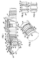
- an electrical connector assembly includes a plug connector member 20 terminating a shielded cable 40, a receptacle connector member 10, a coupling ring 48 rotatably mounted to the plug connector member for coupling the connector members together, and a grounding strap 18 for shielding the electrical connector assembly from EMI.
- the cable 40 comprises one or more center conductors 42, a dielectric body 44 surrounding the conductors, and a conductive braid shield 46 surrounding the dielectric.
- An accessory boot 50 is mounted to the plug connector member for supporting the cable to the back shell of the plug connector. Although not shown, a like accessory boot and shielded cable would extend from the receptacle connector.
- Plug connector member 20 comprises an electrically conductive metallic shell having a mating forward end portion having an outer periphery 24, a conductor receiving back shell or rearward end portion 30, and a radial flange 26 medially of its end portions and having an end wall 28 facing forwardly.
- the back shell 30 includes external thread 32 therearound and transverse end face 34 comprising a plurality of aftwardly extending V-shaped teeth or serrations having valleys 36 and peaks 38, the teeth being provided to facilitate non-rotational connection thereto of an auxiliary accessory.
- Receptacle connector member 10 is compatible for mating to plug connector 20 and will not be described since its details would be understood by one of ordinary skill in the art of assembling electrical connectors.
- the receptacle includes a generally cylindrical shell 12 of electrically conductive material which, when mated, has a forward end face 14 abutting the end wall 28 of flange 26 and its inner surface 16 compressing the grounding strap 18 radially inward against the outer periphery 24 of the plug shell.
- the rearward end face of its back shell includes a plurality of V-shaped serrations.
- Accessory boot 50 includes a generally cylindrical ferrule 56 of electrically conductive material, and a coupling nut 52.
- Ferrule 56 includes a front face 60, a back face 57, and a stepped bore extending coaxially between the front and back faces and comprising a forward bore 62 and a rearward bore 58, the back face 57 and rearward bore 58 being adapted to slidably insert between the braid shield 46 and the dielectric 44.
- the coupling nut 52 is rotatably mounted to the ferrule and includes internal thread 54 for engaging external thread 32 on back shell 30.
- a continuous 360 0 electrically conductive seal is provided between the braid, the accessory boot, and the back shell.
- An end portion of braid shield 46 is fitted tightly about the back face 57 of ferrule 56 and a clamping ring 47 is crimped radially inward and therearound to secure the braid to the sleeve and support the cable to the back shell when the accessory boot has been positioned relative to the back shell of the plug connector member, the inward crimping forming a continuous 360 0 electrically conductive seal between the braid and the ferrule.
- Ferrule 56 includes a pocket defined by the cylindrical sidewall forming forward bore 62 and a transverse end wall 64 defining the transition between the bores, the pocket extending coaxially rearward from the front face 60 to the transverse end wall 64.
- a pair of concentric sleeves 68, 74 of electrically conductive material are mounted adjacent to the back shell and the front face of the ferrule.
- the outer sleeve 68 is disposed in the pocket such that the outer periphery thereof is interference fit against the sidewall of forward bore 62, a rearward axial end face 72 thereof is abutting the end wall 64, and a forward axial end face 70 thereof is comprised of --a plurality of V-shaped teeth.
- the inner sleeve 74 has a rearward and a forward outer periphery 76, 78 and a medial annular shoulder 80 extending radially outward from and around the outer periphery thereof, the rearward outer periphery 76 having a diameter which is adapted to interference fit within the inner periphery of outer sleeve 68 and the forward outer periphery 78 having a diameter which is adapted to interference fit within the inner periphery of back shell 30.
- the annular shoulder 80 defines forward and rearward axial end faces comprised of a plurality of forward facing and rearward facing V-shaped teeth 84, 82 with the rearward facing teeth 82 being adapted to engage the V-shaped teeth 70 extending forwardly from the outer sleeve 68 and the forward facing teeth 84 being adapted to engage the V-shaped teeth extending aftwardly from the back shell.
- Annular shoulder 80 is comprised of an electrically conductive material capable of being plastically deformed, such as, but not limited to deadsoft copper, deadsoft aluminum, silver, or one of the many highly conductive metal or graphite loaded elastomeric materials available from a number of commercial manufacturers.
- the term "deadsoft” generally connotes a material which is as soft (i.e., pliable) as possible without going fluid.
- the interference fit by the inner sleeve 74 within the outer sleeve 68 and within the back shell 30 provides an electrically conductive circuit path 360° therearound to shield the signal carrying conductors against EMI entering and to prevent leakage therefrom.
- the plastic deformation of annular shoulder 80 provides an electrically conductive seal between the end faces of ferrule 56 and back shell 30 and the teeth.
Landscapes
- Details Of Connecting Devices For Male And Female Coupling (AREA)
Applications Claiming Priority (2)
| Application Number | Priority Date | Filing Date | Title |
|---|---|---|---|
| US06/595,879 US4583809A (en) | 1984-04-02 | 1984-04-02 | Electrical connector assembly having means for EMI shielding |
| US595879 | 1984-04-02 |
Publications (2)
| Publication Number | Publication Date |
|---|---|
| EP0158076A2 true EP0158076A2 (de) | 1985-10-16 |
| EP0158076A3 EP0158076A3 (de) | 1988-09-14 |
Family
ID=24385075
Family Applications (1)
| Application Number | Title | Priority Date | Filing Date |
|---|---|---|---|
| EP85102049A Withdrawn EP0158076A3 (de) | 1984-04-02 | 1985-02-25 | Elektrischer Verbindungszusammenbau mit Abschirmungsmittel gegen elektromagnetische Interferenz |
Country Status (4)
| Country | Link |
|---|---|
| US (1) | US4583809A (de) |
| EP (1) | EP0158076A3 (de) |
| JP (1) | JPS60225380A (de) |
| CA (1) | CA1231149A (de) |
Cited By (1)
| Publication number | Priority date | Publication date | Assignee | Title |
|---|---|---|---|---|
| WO2013120870A1 (en) * | 2012-02-14 | 2013-08-22 | Tyco Electronics Amp Gmbh | Housing having a seal |
Families Citing this family (16)
| Publication number | Priority date | Publication date | Assignee | Title |
|---|---|---|---|---|
| US4807891A (en) * | 1987-07-06 | 1989-02-28 | The United States Of America As Represented By The Secretary Of The Air Force | Electromagnetic pulse rotary seal |
| US4808126A (en) * | 1987-10-05 | 1989-02-28 | Itt Corporation | Electrical connector shield |
| US5046964A (en) * | 1989-10-10 | 1991-09-10 | Itt Corporation | Hybrid connector |
| US5211590A (en) * | 1991-12-11 | 1993-05-18 | General Electric Company | Repairable electric cable connector with snap together backshell |
| US5183417A (en) * | 1991-12-11 | 1993-02-02 | General Electric Company | Cable backshell |
| US5472356A (en) * | 1992-03-09 | 1995-12-05 | Itt Corporation | Network connector |
| US5456611A (en) * | 1993-10-28 | 1995-10-10 | The Whitaker Corporation | Mini-UHF snap-on plug |
| US5478254A (en) * | 1994-10-03 | 1995-12-26 | Rolls-Royce, Plc | Electrical connector |
| DE19529692A1 (de) * | 1995-08-11 | 1997-02-13 | Gore W L & Ass Gmbh | Endgehäuse für einen Steckverbinder |
| US6210222B1 (en) | 1999-12-13 | 2001-04-03 | Eagle Comtronics, Inc. | Coaxial cable connector |
| US6416338B1 (en) * | 2001-03-13 | 2002-07-09 | Hubbell Incorporated | Electrical connector with dual action piston |
| US6790081B2 (en) | 2002-05-08 | 2004-09-14 | Corning Gilbert Inc. | Sealed coaxial cable connector and related method |
| US7128603B2 (en) * | 2002-05-08 | 2006-10-31 | Corning Gilbert Inc. | Sealed coaxial cable connector and related method |
| DE102004018430A1 (de) * | 2004-04-06 | 2005-10-27 | ITT Mfg. Enterprises, Inc., Wilmington | Elektrische und mechanische Verbindungsanordnung |
| US9118158B2 (en) | 2013-01-18 | 2015-08-25 | R. Kern Engineering & Manufacturing Corp. | Cable assembly backshell |
| US9680268B1 (en) | 2016-05-18 | 2017-06-13 | Itt Manufacturing Enterprises Llc | Genderless electrical connectors |
Citations (3)
| Publication number | Priority date | Publication date | Assignee | Title |
|---|---|---|---|---|
| US3944317A (en) * | 1975-01-13 | 1976-03-16 | Amex Systems, Inc. | Adapter for shielded electrical cable connections |
| US4408821A (en) * | 1979-07-09 | 1983-10-11 | Amp Incorporated | Connector for semi-rigid coaxial cable |
| EP0091370A2 (de) * | 1982-04-05 | 1983-10-12 | Amphenol Corporation | Elektrischer Verbinder mit einem Abschirmring |
Family Cites Families (17)
| Publication number | Priority date | Publication date | Assignee | Title |
|---|---|---|---|---|
| US2762025A (en) * | 1953-02-11 | 1956-09-04 | Erich P Tilenius | Shielded cable connectors |
| US2958750A (en) * | 1957-03-25 | 1960-11-01 | Mc Graw Edison Co | Protectors for electric circuits |
| NL263948A (de) * | 1960-10-24 | |||
| US3171706A (en) * | 1962-09-18 | 1965-03-02 | Thaddeus E Daniels | Shielded electrical connector |
| US3281756A (en) * | 1964-08-24 | 1966-10-25 | Amp Inc | Coaxial cable connector |
| US3336566A (en) * | 1965-02-01 | 1967-08-15 | Electronic Standards Corp Of A | Microwave push-on connectors |
| US3537065A (en) * | 1967-01-12 | 1970-10-27 | Jerrold Electronics Corp | Multiferrule cable connector |
| US3448430A (en) * | 1967-01-23 | 1969-06-03 | Thomas & Betts Corp | Ground connector |
| US3408610A (en) * | 1967-04-10 | 1968-10-29 | Anthony T. Clarkson | Rotatable coaxial coupling |
| US3659251A (en) * | 1970-05-28 | 1972-04-25 | Electro Adapter Inc | Adapter for electrical cable |
| GB1512626A (en) * | 1974-05-03 | 1978-06-01 | Raychem Ltd | Method of terminating electric cable |
| US4008943A (en) * | 1975-07-17 | 1977-02-22 | Rte Corporation | High voltage cable terminator having a fault actuated probe |
| DE2727591A1 (de) * | 1976-06-25 | 1978-01-05 | Bunker Ramo | Aussenleiteranschluss fuer koaxialverbinder |
| US4243290A (en) * | 1978-10-30 | 1981-01-06 | Williams Robert A | Shield termination means for electrical connector |
| US4296986A (en) * | 1979-06-18 | 1981-10-27 | Amp Incorporated | High voltage hermetically sealed connector |
| US4330166A (en) * | 1979-08-16 | 1982-05-18 | Automation Industries, Inc. | Electrical connector substantially shielded against EMP and EMI energy |
| US4248492A (en) * | 1979-08-31 | 1981-02-03 | The Bendix Corporation | Electrical connector assembly having means for shielding against electromagnetic interference |
-
1984
- 1984-04-02 US US06/595,879 patent/US4583809A/en not_active Expired - Fee Related
-
1985
- 1985-02-25 EP EP85102049A patent/EP0158076A3/de not_active Withdrawn
- 1985-04-02 JP JP60068594A patent/JPS60225380A/ja active Pending
- 1985-04-02 CA CA000478192A patent/CA1231149A/en not_active Expired
Patent Citations (3)
| Publication number | Priority date | Publication date | Assignee | Title |
|---|---|---|---|---|
| US3944317A (en) * | 1975-01-13 | 1976-03-16 | Amex Systems, Inc. | Adapter for shielded electrical cable connections |
| US4408821A (en) * | 1979-07-09 | 1983-10-11 | Amp Incorporated | Connector for semi-rigid coaxial cable |
| EP0091370A2 (de) * | 1982-04-05 | 1983-10-12 | Amphenol Corporation | Elektrischer Verbinder mit einem Abschirmring |
Cited By (2)
| Publication number | Priority date | Publication date | Assignee | Title |
|---|---|---|---|---|
| WO2013120870A1 (en) * | 2012-02-14 | 2013-08-22 | Tyco Electronics Amp Gmbh | Housing having a seal |
| US9461397B2 (en) | 2012-02-14 | 2016-10-04 | Te Connectivity Germany Gmbh | Housing having a seal |
Also Published As
| Publication number | Publication date |
|---|---|
| US4583809A (en) | 1986-04-22 |
| JPS60225380A (ja) | 1985-11-09 |
| EP0158076A3 (de) | 1988-09-14 |
| CA1231149A (en) | 1988-01-05 |
Similar Documents
| Publication | Publication Date | Title |
|---|---|---|
| US4808128A (en) | Electrical connector assembly having means for EMI shielding | |
| CA1231150A (en) | Electrical connector assembly having means for emi shielding | |
| US4583809A (en) | Electrical connector assembly having means for EMI shielding | |
| US3744011A (en) | Coaxial cable connector | |
| US5352134A (en) | RF shielded coaxial cable connector | |
| EP0091370B1 (de) | Elektrischer Verbinder mit einem Abschirmring | |
| US6183298B1 (en) | Connector for coaxial cable with friction locking arrangement | |
| US4668043A (en) | Solderless connectors for semi-rigid coaxial cable | |
| US5681172A (en) | Multi-pole electrical connector with ground continuity | |
| US5046964A (en) | Hybrid connector | |
| US4340269A (en) | Coaxial electrical connector | |
| EP0632537B1 (de) | Kabelverbinder mit Zugentlastung | |
| US3835443A (en) | Electrical connector shield | |
| US4531790A (en) | Electrical connector grounding ring | |
| US4227765A (en) | Coaxial electrical connector | |
| US4037909A (en) | Coaxial cable connector with energy loss prevention | |
| GB1154181A (en) | Coaxial Cable Connector | |
| US5167520A (en) | Cup fit plug connector | |
| GB1325720A (en) | Cable shield termination for electrical connectors | |
| CA2122119A1 (en) | Lightweight Connector for a Coaxial Cable | |
| WO1986006883A1 (en) | Wire seal | |
| US6033260A (en) | Shielding-member-containing connector assembly | |
| US6048227A (en) | Connector backshell | |
| US4483579A (en) | Electrical connector having improved coupling ring | |
| US5478254A (en) | Electrical connector |
Legal Events
| Date | Code | Title | Description |
|---|---|---|---|
| PUAI | Public reference made under article 153(3) epc to a published international application that has entered the european phase |
Free format text: ORIGINAL CODE: 0009012 |
|
| AK | Designated contracting states |
Designated state(s): DE FR GB IT |
|
| PUAL | Search report despatched |
Free format text: ORIGINAL CODE: 0009013 |
|
| AK | Designated contracting states |
Kind code of ref document: A3 Designated state(s): DE FR GB IT |
|
| STAA | Information on the status of an ep patent application or granted ep patent |
Free format text: STATUS: THE APPLICATION IS DEEMED TO BE WITHDRAWN |
|
| 18D | Application deemed to be withdrawn |
Effective date: 19890315 |
|
| RIN1 | Information on inventor provided before grant (corrected) |
Inventor name: PRESSEL, PAUL IRWIN Inventor name: BRUSH, ROBERT WILLIAM, SR. Inventor name: WERTH, DEE ADOLPH |