EP0157746B1 - Lötkolben mit Einrichtung zum Beseitigen von Lötdämpfen durch Absaugen - Google Patents
Lötkolben mit Einrichtung zum Beseitigen von Lötdämpfen durch Absaugen Download PDFInfo
- Publication number
- EP0157746B1 EP0157746B1 EP85850086A EP85850086A EP0157746B1 EP 0157746 B1 EP0157746 B1 EP 0157746B1 EP 85850086 A EP85850086 A EP 85850086A EP 85850086 A EP85850086 A EP 85850086A EP 0157746 B1 EP0157746 B1 EP 0157746B1
- Authority
- EP
- European Patent Office
- Prior art keywords
- soldering
- suction
- channel
- heating element
- handle
- Prior art date
- Legal status (The legal status is an assumption and is not a legal conclusion. Google has not performed a legal analysis and makes no representation as to the accuracy of the status listed.)
- Expired
Links
Images
Classifications
-
- B—PERFORMING OPERATIONS; TRANSPORTING
- B23—MACHINE TOOLS; METAL-WORKING NOT OTHERWISE PROVIDED FOR
- B23K—SOLDERING OR UNSOLDERING; WELDING; CLADDING OR PLATING BY SOLDERING OR WELDING; CUTTING BY APPLYING HEAT LOCALLY, e.g. FLAME CUTTING; WORKING BY LASER BEAM
- B23K3/00—Tools, devices or special appurtenances for soldering, e.g. brazing, or unsoldering, not specially adapted for particular methods
- B23K3/02—Soldering irons; Bits
- B23K3/029—Solder or residue removing devices
Definitions
- the invention relates to a soldering iron having means for withdrawing by suction soldering fumes created by resin present in the solder, comprising a handle having an electrical heating element with an outer metal casing, a soldering tip connected to the electrical heating element, and a metallic suction nozzle, the front end of which lies in the proximity of the soldering tip and the rear end of which is connected to a channel in the handle, this channel in turn being connected to a flexible plastic hose connected to a suction source.
- soldering irons are particularly suited for removing the irritating and often harmful fumes generated by the solder flux incorporated in the solder or used separately in conjunction therewith, this flux containing volatile resins.
- the most serious drawback with soldering irons of this kind is the relatively short time in which they can be used before needing to clean the nozzle and the suction channel. In normal soldering irons of this kind, nominally about 30 liters of air are drawn through the nozzle each minute, which means that the temperature of the nozzle is much lower than that of the solder fumes generated. This means in turn that vaporized resins
- DD-A-128 262 relates to a soldering iron for withdrawing by suction fume gases.
- the electrical heating element of the known soldering iron is surrounded by a tube, which in turn is connected to a suction channel arranged in the handle.
- the suction channel is connected to a flexible suction hose.
- DE-C-562 094 discloses a soldering iron with a metallic suction tube to be connected to a flexible hose.
- the suction tube is certainly connected to a metallic clamp to the iron but between the handle and the electrical heating element, which means that only a minor heat transfer occurs and that the nozzle of the suction tube will be cooled down by the insucked air to about room temperature thereby causing a solidification of vaporized resins within the suction tube.
- US-A-4 358 662 discloses an electric soldering iron provided with an elongated heater barrel extending from a handle and a soldering tip projecting from the end of the barrel.
- the barrel is provided with a thermally isolated fume suction attachment surrounding the tip and including a suction tube connected to a flexible hose.
- the metallic suction tube will cool down the vaporized resin fumes causing deposits within the suction tube which must be chemically or mechanically removed.
- a prime object of the invention to provide a soldering iron in which the deposits of resin in the nozzle and/or suction channel is completely or at least substantially avoided, and to shift the unavoidable deposition of tough resin to the readily accessible flexible hose.
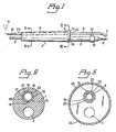
- the illustrated soldering iron has a handle 1 made of plastics, wood or some other suitable material, a heating element 2 which extends from one end of the handle 1 and which has a metal outer casing, suitably made of steel.
- the heating element 2 has an internal resistance member to which voltage is applied via a cable 3 passing through a bore 4 in the longitudinal direction of the handle 1.
- Mounted on the outer end of the element 2 is an exchangeable soldering tip or bit 5 with which solder and flux are melted to effect a soldering operation.
- the cable 3 is not shown in Figures 2 and 3.
- Extending along the element 2 is a metal tubular suction nozzle 6 with the outer end 7 thereof directed towards the soldering site.
- the rear end 8 of the nozzle 6 is connected to a channel 9 passing through the handle, this channel in turn being connected to a suction hose 10 which is connected to a suction source 11.
- a suction source 11 or the suction fan, is operating fumes generated during a soldering operation are withdrawn from the soldering site by suction and depart from the fan 11 through a filter means not shown.
- this heat transfer connection comprises a metal ring 12 which is placed on the metal casing of the element 2 and which is welded or soldered to the suction nozzle via a metal bridge formed on the ring 12. This enables the nozzle 6 to be readily drawn from the heating element.
- the metal ring 12 may be supplemented with one more metal ring attached to the nozzle 6, or the ring may be given an axial length corresponding, for example, to the total length of the metal casing, in which case the bridge 13 comprises an elongated flange between the long ring or sleeve and the nozzle.
- the suction hose 10 which is inserted into a bore 15 in the handle extends through the whole length of the channel 9 to a location approximately adjacent the end of the soldering tip 5 facing said handle, wherewith the end 8 of the nozzle 6 is inserted into this part of the suction hose through an opening located in an end plate 14.
- the suction hose 10 is considered to comprise a continuous length of hose extending to the suction source 11. It will be understood, however, that the hose may also comprise a plurality of hose sections joined together by means of connectors herefor. At least that part of the suction hose located within the handle preferably comprises a silicon polymer.
- longitudinally extending fins 16, 17, 18, 19 or like spacers may be arranged in the bore 15, as illustrated in Figures 2 and 3, these spacers forming between the inner wall 20 of the bore and the outer wall 21 of the hose 10 at least one air through-flow channel, for example the channel 22, which communicates with ambient air.
- the handle 1 may be provided with a hollow cover 23 closed by means of the cover plate 14 and into which the channel or channels 22 discharge. In this respect air can be drawn in either by sealing the cover plate 14 to render the same pervious or, for example, by providing a vent, for example the hole 24, in the wall of the cover 23.
- the channel or channels 22 also opens out, or open out, in a sleeve 25, Figure 1, and can there be connected to a suction source, which suitably comprises the suction source 11.
- a suction source which suitably comprises the suction source 11.
- this layer can be rapidly removed by interrupting the insuction of air.
- the nozzle will be quickly heated to a high temperature, causing the resin to melt and run from the nozzle.
- the ring or sleeve 12 may comprise a metal clamp means connected with the nozzle 6 and clamped firmly on the heating element 2.
- the illustrated slightly conical shape of the handle 1 can be replaced with any suitable ergonometrical configuration.
Landscapes
- Engineering & Computer Science (AREA)
- Mechanical Engineering (AREA)
- Electric Connection Of Electric Components To Printed Circuits (AREA)
- Transition And Organic Metals Composition Catalysts For Addition Polymerization (AREA)
- Peptides Or Proteins (AREA)
- Micro-Organisms Or Cultivation Processes Thereof (AREA)
- Physical Or Chemical Processes And Apparatus (AREA)
- Nozzles For Electric Vacuum Cleaners (AREA)
- Cleaning In General (AREA)
- Magnetically Actuated Valves (AREA)
- Electromagnets (AREA)
Claims (6)
Priority Applications (1)
| Application Number | Priority Date | Filing Date | Title |
|---|---|---|---|
| AT85850086T ATE30528T1 (de) | 1984-04-05 | 1985-03-12 | Loetkolben mit einrichtung zum beseitigen von loetdaempfen durch absaugen. |
Applications Claiming Priority (2)
| Application Number | Priority Date | Filing Date | Title |
|---|---|---|---|
| SE8401915A SE437341B (sv) | 1984-04-05 | 1984-04-05 | Lodkolv med organ for avsugning av lodrok |
| SE8401915 | 1984-04-05 |
Publications (2)
| Publication Number | Publication Date |
|---|---|
| EP0157746A1 EP0157746A1 (de) | 1985-10-09 |
| EP0157746B1 true EP0157746B1 (de) | 1987-11-04 |
Family
ID=20355480
Family Applications (1)
| Application Number | Title | Priority Date | Filing Date |
|---|---|---|---|
| EP85850086A Expired EP0157746B1 (de) | 1984-04-05 | 1985-03-12 | Lötkolben mit Einrichtung zum Beseitigen von Lötdämpfen durch Absaugen |
Country Status (9)
| Country | Link |
|---|---|
| US (1) | US4607151A (de) |
| EP (1) | EP0157746B1 (de) |
| JP (1) | JPS6123569A (de) |
| AT (1) | ATE30528T1 (de) |
| CA (1) | CA1234879A (de) |
| DE (1) | DE3560863D1 (de) |
| DK (1) | DK152285A (de) |
| FI (1) | FI77393C (de) |
| SE (1) | SE437341B (de) |
Families Citing this family (17)
| Publication number | Priority date | Publication date | Assignee | Title |
|---|---|---|---|---|
| CA55042S (en) | 1985-07-12 | 1985-09-24 | Adcola Prod Ltd | Fume extracting soldering iron |
| US4796795A (en) * | 1987-10-13 | 1989-01-10 | Cooper Industries, Inc. | Flux fume removal device |
| US4965433A (en) * | 1988-12-09 | 1990-10-23 | The Boeing Company | Vacuum pickup tool with integrally heated soldering tip |
| GB2234696A (en) * | 1989-07-29 | 1991-02-13 | Chiou Liang Wang | Electric welding and soldering iron |
| DE59001696D1 (de) * | 1989-09-29 | 1993-07-15 | Siemens Nixdorf Inf Syst | Loetvorrichtung zum aufloeten von bauelementen auf leiterplatten. |
| US5127572A (en) * | 1989-11-20 | 1992-07-07 | Manouchehr Pazhouhesh | Soldering method and tool |
| US5280851A (en) * | 1992-07-09 | 1994-01-25 | Newlab Electronic S.A. | Soldering-vapor exhaust device |
| US5524809A (en) * | 1994-08-22 | 1996-06-11 | The United States Of America As Represented By The United States Department Of Energy | Soldering instrument safety improvements |
| US7550693B2 (en) * | 2005-02-04 | 2009-06-23 | Honeywell International Inc. | Hand-held laser welding wand with improved optical assembly serviceability features |
| US20090050673A1 (en) * | 2007-05-24 | 2009-02-26 | Charles Peter Althoff | Soldering Apparatus and Solder Tip |
| US7699208B2 (en) | 2007-11-30 | 2010-04-20 | Nordson Corporation | Soldering tip, soldering iron, and soldering system |
| US20120024834A1 (en) * | 2010-07-30 | 2012-02-02 | Floyd William Kaylor | Melting pen |
| CN102069257A (zh) * | 2010-12-30 | 2011-05-25 | 东莞市长田电子有限公司 | 一种用于抽除焊接烟雾的抽烟装置 |
| CN103372699A (zh) * | 2012-04-18 | 2013-10-30 | 鸿富锦精密工业(深圳)有限公司 | 电烙铁 |
| CN206653051U (zh) * | 2017-03-30 | 2017-11-21 | 合肥京东方光电科技有限公司 | 一种电烙铁及焊接装置 |
| EP3888585B1 (de) * | 2020-03-30 | 2022-11-23 | DENTSPLY SIRONA Inc. | Handwerkzeug zum trennen einer tiefgezogenen, kieferumspannenden dentalen vorrichtung aus thermoformfolie und verwendungsverfahren |
| CN114888391B (zh) * | 2022-06-11 | 2022-12-02 | 恩平市麦之声电子科技有限公司 | 一种限制焊接热影响区的pcb板锡焊装置 |
Family Cites Families (6)
| Publication number | Priority date | Publication date | Assignee | Title |
|---|---|---|---|---|
| DE562094C (de) * | 1932-10-21 | Aeg | Loetkolben | |
| US2041018A (en) * | 1934-04-25 | 1936-05-19 | Ralph C Persons | Electric soldering iron |
| DD128262A1 (de) * | 1976-11-25 | 1977-11-09 | Joachim Hartmann | Loetkolben mit absaugeinrichtung fuer loetdaempfe |
| US4358662A (en) * | 1980-07-11 | 1982-11-09 | Western Electric Company, Inc. | Thermally isolated fume exhausting attachment for soldering irons |
| JPS57121322A (en) * | 1981-01-21 | 1982-07-28 | Mitsubishi Electric Corp | Time limit relay |
| EP0100229A1 (de) * | 1982-07-26 | 1984-02-08 | Adcola Products Limited | Lötwerkzeug |
-
1984
- 1984-04-05 SE SE8401915A patent/SE437341B/sv not_active IP Right Cessation
-
1985
- 1985-03-12 EP EP85850086A patent/EP0157746B1/de not_active Expired
- 1985-03-12 AT AT85850086T patent/ATE30528T1/de not_active IP Right Cessation
- 1985-03-12 DE DE8585850086T patent/DE3560863D1/de not_active Expired
- 1985-03-15 FI FI851034A patent/FI77393C/fi not_active IP Right Cessation
- 1985-03-15 US US06/711,684 patent/US4607151A/en not_active Expired - Fee Related
- 1985-03-19 CA CA000476868A patent/CA1234879A/en not_active Expired
- 1985-04-01 JP JP6672385A patent/JPS6123569A/ja active Pending
- 1985-04-03 DK DK152285A patent/DK152285A/da active Protection Beyond IP Right Term
Also Published As
| Publication number | Publication date |
|---|---|
| ATE30528T1 (de) | 1987-11-15 |
| FI851034L (fi) | 1985-10-06 |
| FI77393B (fi) | 1988-11-30 |
| FI851034A0 (fi) | 1985-03-15 |
| JPS6123569A (ja) | 1986-02-01 |
| SE8401915D0 (sv) | 1984-04-05 |
| DK152285A (da) | 1985-10-06 |
| EP0157746A1 (de) | 1985-10-09 |
| FI77393C (fi) | 1989-03-10 |
| DE3560863D1 (en) | 1987-12-10 |
| CA1234879A (en) | 1988-04-05 |
| SE437341B (sv) | 1985-02-25 |
| DK152285D0 (da) | 1985-04-03 |
| US4607151A (en) | 1986-08-19 |
Similar Documents
| Publication | Publication Date | Title |
|---|---|---|
| EP0157746A1 (de) | Lötkolben mit Einrichtung zum Beseitigen von Lötdämpfen durch Absaugen | |
| US4358662A (en) | Thermally isolated fume exhausting attachment for soldering irons | |
| US3803381A (en) | Arc welding gun | |
| GB2181686A (en) | Motorised wire feeding device | |
| EP0533358A1 (de) | Dampferzeuger | |
| US4435636A (en) | Desoldering tool | |
| US3163145A (en) | Solder removing tool | |
| US5182435A (en) | Electric soldering iron with forked suction pipe for removing soldering smoke and cooling the handle of the soldering iron | |
| EP0125109A2 (de) | Schutzvorrichtung für Warmluftpistole | |
| ATE175920T1 (de) | Heizbare spritzgiessdüse mit schützrohren | |
| US3963897A (en) | Electrically heated solder removing bit | |
| US3419709A (en) | Blackbody radiating device with a protective hood | |
| US4225076A (en) | Desolderer and heater assembly for use therewith | |
| JP2005288545A (ja) | はんだ取扱い器具 | |
| KR950031341A (ko) | 납땜기구 | |
| US20040195228A1 (en) | Cartridge-type soldering iron | |
| GB2026677A (en) | Spiral Heat Exchanges | |
| US4804129A (en) | In-line solder extractor and heater assembly for use therewith | |
| HU208094B (en) | Outsoldering device | |
| DE4016381C2 (de) | ||
| RU2057016C1 (ru) | Электрическая горелка | |
| AU620663B2 (en) | Hot gas soldering system | |
| US3245597A (en) | Desoldering tool | |
| US4698485A (en) | Heater device | |
| DE9312436U1 (de) | Gasdüsenaufnahmekörper für wassergekühlte Hand- oder Automatenschweiß- und Schneidbrenner |
Legal Events
| Date | Code | Title | Description |
|---|---|---|---|
| PUAI | Public reference made under article 153(3) epc to a published international application that has entered the european phase |
Free format text: ORIGINAL CODE: 0009012 |
|
| AK | Designated contracting states |
Designated state(s): AT BE CH DE FR GB IT LI NL |
|
| 17P | Request for examination filed |
Effective date: 19850913 |
|
| 17Q | First examination report despatched |
Effective date: 19860930 |
|
| GRAA | (expected) grant |
Free format text: ORIGINAL CODE: 0009210 |
|
| AK | Designated contracting states |
Kind code of ref document: B1 Designated state(s): AT BE CH DE FR GB IT LI NL |
|
| REF | Corresponds to: |
Ref document number: 30528 Country of ref document: AT Date of ref document: 19871115 Kind code of ref document: T |
|
| REF | Corresponds to: |
Ref document number: 3560863 Country of ref document: DE Date of ref document: 19871210 |
|
| ET | Fr: translation filed | ||
| ITF | It: translation for a ep patent filed | ||
| PLBE | No opposition filed within time limit |
Free format text: ORIGINAL CODE: 0009261 |
|
| STAA | Information on the status of an ep patent application or granted ep patent |
Free format text: STATUS: NO OPPOSITION FILED WITHIN TIME LIMIT |
|
| 26N | No opposition filed | ||
| PGFP | Annual fee paid to national office [announced via postgrant information from national office to epo] |
Ref country code: AT Payment date: 19900314 Year of fee payment: 6 |
|
| PGFP | Annual fee paid to national office [announced via postgrant information from national office to epo] |
Ref country code: BE Payment date: 19900323 Year of fee payment: 6 |
|
| PGFP | Annual fee paid to national office [announced via postgrant information from national office to epo] |
Ref country code: FR Payment date: 19900327 Year of fee payment: 6 |
|
| PGFP | Annual fee paid to national office [announced via postgrant information from national office to epo] |
Ref country code: CH Payment date: 19900328 Year of fee payment: 6 |
|
| ITTA | It: last paid annual fee | ||
| PGFP | Annual fee paid to national office [announced via postgrant information from national office to epo] |
Ref country code: NL Payment date: 19900331 Year of fee payment: 6 Ref country code: GB Payment date: 19900331 Year of fee payment: 6 |
|
| PGFP | Annual fee paid to national office [announced via postgrant information from national office to epo] |
Ref country code: DE Payment date: 19900531 Year of fee payment: 6 |
|
| PG25 | Lapsed in a contracting state [announced via postgrant information from national office to epo] |
Ref country code: GB Effective date: 19910312 Ref country code: AT Effective date: 19910312 |
|
| PG25 | Lapsed in a contracting state [announced via postgrant information from national office to epo] |
Ref country code: LI Effective date: 19910331 Ref country code: CH Effective date: 19910331 Ref country code: BE Effective date: 19910331 |
|
| BERE | Be: lapsed |
Owner name: LECTROSTATIC MARKNADS A.B. Effective date: 19910331 |
|
| PG25 | Lapsed in a contracting state [announced via postgrant information from national office to epo] |
Ref country code: NL Effective date: 19911001 |
|
| GBPC | Gb: european patent ceased through non-payment of renewal fee | ||
| NLV4 | Nl: lapsed or anulled due to non-payment of the annual fee | ||
| PG25 | Lapsed in a contracting state [announced via postgrant information from national office to epo] |
Ref country code: FR Effective date: 19911129 |
|
| REG | Reference to a national code |
Ref country code: CH Ref legal event code: PL |
|
| PG25 | Lapsed in a contracting state [announced via postgrant information from national office to epo] |
Ref country code: DE Effective date: 19920101 |
|
| REG | Reference to a national code |
Ref country code: FR Ref legal event code: ST |