EP0157670A1 - Transformer and method of producing it - Google Patents
Transformer and method of producing it Download PDFInfo
- Publication number
- EP0157670A1 EP0157670A1 EP85400408A EP85400408A EP0157670A1 EP 0157670 A1 EP0157670 A1 EP 0157670A1 EP 85400408 A EP85400408 A EP 85400408A EP 85400408 A EP85400408 A EP 85400408A EP 0157670 A1 EP0157670 A1 EP 0157670A1
- Authority
- EP
- European Patent Office
- Prior art keywords
- winding
- windings
- magnetic
- circuits
- transformer according
- Prior art date
- Legal status (The legal status is an assumption and is not a legal conclusion. Google has not performed a legal analysis and makes no representation as to the accuracy of the status listed.)
- Granted
Links
Images


Classifications
-
- H—ELECTRICITY
- H01—ELECTRIC ELEMENTS
- H01F—MAGNETS; INDUCTANCES; TRANSFORMERS; SELECTION OF MATERIALS FOR THEIR MAGNETIC PROPERTIES
- H01F41/00—Apparatus or processes specially adapted for manufacturing or assembling magnets, inductances or transformers; Apparatus or processes specially adapted for manufacturing materials characterised by their magnetic properties
- H01F41/02—Apparatus or processes specially adapted for manufacturing or assembling magnets, inductances or transformers; Apparatus or processes specially adapted for manufacturing materials characterised by their magnetic properties for manufacturing cores, coils, or magnets
-
- H—ELECTRICITY
- H01—ELECTRIC ELEMENTS
- H01F—MAGNETS; INDUCTANCES; TRANSFORMERS; SELECTION OF MATERIALS FOR THEIR MAGNETIC PROPERTIES
- H01F30/00—Fixed transformers not covered by group H01F19/00
- H01F30/06—Fixed transformers not covered by group H01F19/00 characterised by the structure
- H01F30/12—Two-phase, three-phase or polyphase transformers
Definitions
- the present invention relates to an electrical transformer of any power, single-phase or polyphase, and to its manufacturing process.
- the present invention proposes to remedy the drawbacks set out above by providing a transformer that can be produced rapidly, with a considerably lower production investment than that required at present, resulting, consequently, in a significant reduction in the cost prices, this cost price being further lowered by a reduction in the manufacturing costs of the windings electrical and mechanical circuits.
- the transformer object of this invention is characterized by a low operating cost, since the invention lends itself particularly well to the use of amorphous materials, very energy-consuming, both for their manufacture and for their use for the realization of magnetic circuits, which allows, in particular, to obtain windings of low weight, therefore low energy consumption, in operation.
- a transformer according to the invention is essentially characterized in that it comprises: at least one electrical winding, consisting of a wire or a strip of a good conductive metal, such as aluminum, wound around a annular carcass, and at least one magnetic circuit, consisting of at least one elementary circuit, produced by winding tapes of magnetic sheets, which is provided with a window for the passage of the winding, which has the form of a irregular polygon, having an axis of symmetry.
- a polyphase transformer is characterized in that its windings are arranged, contiguous by their internal face, so that the planes passing through these internal faces of the windings form a dihedral of angle 60 °, the magnetic circuits embracing the windings two by two, for each of them.
- the magnetic circuits are positioned and maintained on a support produced in the form of a plate allowing the passage of the windings, and whose configuration is such that it does not constitute a turn embraced by the windings.
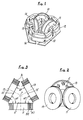
- each electrical winding, high or low voltage is produced from a wire or an aluminum strip A, wound around a carcass having the shape of a rim.
- Each winding has a small width, opposite the usual widths, and it has a small number of turns.
- the input and output connections C of each winding 11, 13 and 15 open into the interior surface of each annular winding carcass (Fig. 2).
- the magnetic transformer circuit illustrated in Figures 1 to 5 therefore consists of three strictly identical elements, 10, 12, 14, coming, for each of them, to embrace two consecutive windings.
- the window 18, 20, 22, respectively, of each elementary magnetic circuit 10, 12, 14, consists of an irregular polygon, of six sides in this example of nonlimiting embodiment, but which has an axis of symmetry.
- the axes of symmetry of each of the windows pass through a common point P, which is also the point of intersection of the axes of each winding.
- Each magnetic circuit such as 10, 12, 14, consists of elementary circuits, manufactured for example by winding around a form of winding of a magnetic strip, for example made of amorphous materials, of constant width.
- the circuits are arranged on the support plate 16, by stacking their elementary components, which are immobilized, for example, using glue dots.
- the magnetic circuits are at no time in permanent contact with the windings 11, 13, 15, or with their supports. They are therefore not subjected to dynamic forces, the only constraints which are exerted on them being those due to their own weight.
- the invention makes it possible to produce magnetic circuit elements of different dimensions, but of constant width, which has a certain advantage, in particular when using amorphous materials (possibility of storing only one width, for manufacturing transformers of different powers. ).
- each magnetic circuit can be inscribed in a semicircle (Fig. 6 and 6a).
- this section can be stepped, as shown in Figure 6, this section can be obtained by successive windings of ribbons of magnetic material of defined width.
- This section can also be polygonal, as illustrated in the Figure. 6a where two magnified circuits are shown ticks 10a, 12a of polygonal section embracing a winding I la.
- the polygonal section can be obtained by winding strips of polygonal shape, wound along their long axis, these polygonal strips generally being produced by slitting strips with parallel edges. Without departing from the scope of the invention, it is possible to provide any other form of section than those illustrated in FIGS. 6 and 6a.
- the support plate 16 receiving the magnetic circuits 10, 12, 14 is produced in the form of a metal plate of sufficient thickness to support the weight of the magnetic circuits and the windings, without undergoing deformations.
- the shape of this support plate 16 is such that it envelops the exterior contour of the magnetic circuits 10, 12, 14, and it has three openings on the exterior, 22, 24, 26, so that the support plate does not constitute, for each winding, a parasitic turn of harmful influence.
- the magnetic circuits are maintained on the support plate by any appropriate means opposing their sliding, for example by tabs (not shown in the drawing).
- Figure 10 being a view from below of the support plate 16, that is to say say in the inverted position relative to Figure 1.
- these means comprise, for each winding such as 11, a yoke 28, produced using a folded sheet, which covers the part of the winding which projects under the support plate 16, as seen in Figure 10.
- This yoke 28 is fixed on the plate 16, and it comprises, in the lower part ( Figure 10 being in the inverted position relative to the effective position), two rolling axes 30 and 30 'on which the annular carcass of the winding lI. These axes rotate in the yoke 28, and they therefore allow the carcass of the winding 11 to rotate relative to this yoke, which ensures ua axial and radial positioning of each carcass, and therefore of each corresponding winding, such as 11 , relative to the plate 16.
- the carcass of each winding, such as 11, is then secured to the support plate 16, so that the different windings are positioned precisely with respect to the magnetic circuits.
- fixing cubes 32, 32 ′ can be provided, which are fixed on the plate 16 and on the cheeks of the carcasses of the windings.
- the yoke 28 can be used, according to the invention, to wind the strips or wires of conductive material on the annular carcasses, as shown in FIG. 9.
- the winding of the windings is carried out, in fact, by subjecting the carcass II to a rotational movement on the shafts 30 and 30 1 , using a geared motor 34 driving a shaft 36, for example covered with rubber, which is applied to the periphery of the two cheeks of the carcass.
- the winding of the strip B of the conductive material (preferably aluminum) and of its insulating strips I is controlled using an electronic counter 38, actuated by a magnetic detector 40, positioned in a housing 40 'made in the yoke 28, which is excited by a metal counting pad 42, fixed to the outer cheek of the carcass.
- This arrangement allows a very precise realization of each winding of the transformer object of the invention. We can associate with this device a microprocessor, which ensures robotization of all operations.
- the device which has just been described makes it possible to produce mechanically very robust winding-carcass assemblies, supporting the electro-dynamic forces during short circuits.
- the annular carcasses on which the windings are wound can be produced in various ways. They may consist, for example, of two side flanges or side plates each provided with an axial recess comprising a shoulder, so as to be able to wind, around the shoulders, an insulating strip which constitutes the axis of the carcass. A coil with an insulating axis is thus produced, which ensures continuity of the insulation of the windings opposite the portions of the internal magnetic circuit at each bearing, which constitutes an important advantage compared with the devices according to the prior art, where this advantage is obtained using expensive and fragile nestings.
- the invention is not limited to the production of polyphase transformers. It makes it possible, in the same way as described above, to produce single-phase transformers.
- Figure 7 shows an exemplary embodiment of a single-phase transformer according to the present invention, which comprises a magnetic circuit 44 and two electrical windings 46, 46 '
- Figure 8 shows an exemplary embodiment of a single-phase transformer according to the invention which comprises two magnetic circuits 48, 48 ', and a single electrical winding 50.
Abstract
Description
La présente invention est relative à un transformateur électrique de toute puissance, monophasé ou polyphasé, et à son procédé de fabrication.The present invention relates to an electrical transformer of any power, single-phase or polyphase, and to its manufacturing process.
On connaît les différentes façons de réaliser un transformateur :
- 1 - soit, on commence par réaliser les enroulements électriques, puis on constitue le circuit magnétique autour des enroulements électriques. Ce procédé est celui qui est généralement utilisé en Europe. Son inconvénient essentiel réside dans la discontinuité du circuit magnétique (qui est réalisé, soit par enroulement de feuillard et découpe, soit par juxtaposition de pièces découpées dans des feuillards), qui constitue un élément fortement négatif pour atteindre un rendement économique optimal. En outre, le matériau magnétique est sous utilisé ;
- 2 - soit, on commence par réaliser le circuit magnétique, puis on bobine les enroulements électriques autour des circuits ainsi obtenus. Le bobinage peut être effectué à l'aide d'une machine à bobiner torique, mais cette technique est fort longue, et donc coûteuse, et elle est limitée par les capacités des machines actuellement disponibles. On peut également réaliser ce bobinage en faisant tourner un support cylindrique autour du circuit magnétique, en enroulant le fil ou la bande conductrice sur ce support. Cette technique présente un grand intérêt, mais son développement se heurte à des difficultés de mise en oeuvre non encore surmontées :
- . la vitesse de bobinage reste faible, par suite du faible jeu support de bobinage/circuit magnétique, et de la difficulté à positionner et stabiliser ces deux éléments, pour cette opération ;
- . les entrées et les sorties des enroulements électriques posent des problèmes, notamment en ce qui concerne leur localisation, leur passage au travers des fenêtres des circuits magnétiques lors du bobinage, et leur protection pendant cette même opération ;
- . le calage, qui est ensuite réalisé, des enroulements électriques sur le circuit magnétique, reste difficile, et il doit faire appel à des systèmes mécaniques annexes, compliqués et coûteux. La tenue aux efforts dynamiques, lors des courts-circuits, de l'ensemble enroulements électriques/circuits magnétiques, vitale pour le transformateur, dépend de ce calage.
- 1 - either, we start by making the electrical windings, then we constitute the magnetic circuit around the electrical windings. This process is the one generally used in Europe. Its essential drawback lies in the discontinuity of the magnetic circuit (which is produced either by winding a strip and cutting, or by juxtaposition of pieces cut from strips), which constitutes a strongly negative element in order to achieve optimum economic efficiency. In addition, the magnetic material is underused;
- 2 - either, we start by making the magnetic circuit, then we wind the electrical windings around the circuits thus obtained. Winding can be carried out using an O-ring winding machine, but this technique is very long, and therefore expensive, and is limited by the capacities of the machines currently available. We can also realize this winding in weak sant turn a cylindrical support around the magnetic circuit, by winding the wire or the conductive strip on this support. This technique is of great interest, but its development comes up against implementation difficulties not yet overcome:
- . the winding speed remains low, due to the low clearance of the winding support / magnetic circuit, and the difficulty in positioning and stabilizing these two elements, for this operation;
- . the inputs and outputs of the electrical windings pose problems, in particular as regards their location, their passage through the windows of the magnetic circuits during winding, and their protection during this same operation;
- . the setting, which is then carried out, of the electrical windings on the magnetic circuit, remains difficult, and it must use additional mechanical systems, complicated and expensive. The resistance to dynamic forces, during short circuits, of the electrical windings / magnetic circuits assembly, vital for the transformer, depends on this setting.
Par ailleurs, dans la mise en oeuvre des deux procédés examinés ci-dessus, les matériaux ne sont pas employés à leur capacité maximale. Ces procédés connus ne permettent donc pas de tendre vers le coût économique le plus faible, aussi bien en ce qui concerne la fabrication et l'exploitation des transformateurs ainsi réalisés que l'énergie consommée (pertes "Fer" dues au circuit magnétique, et pertes "cuivre" dues aux enroulements).Furthermore, in the implementation of the two methods examined above, the materials are not used to their maximum capacity. These known methods therefore do not make it possible to aim for the lowest economic cost, both with regard to the manufacture and operation of the transformers thus produced and with the energy consumed ("Iron" losses due to the magnetic circuit, and losses "copper" due to windings).
La présente invention se propose de remédier aux inconvénients exposés ci-dessus en apportant un transformateur pouvant être produit rapidement, avec un investissement de production considérablement plus faible que celui nécessaire à l'heure actuelle, se traduisant, par conséquent, par une diminution importante des prix de revient, ce prix de revient étant encore abaissé par une réduction des coûts de fabrication des enroulements électriques et des circuits mécaniques. Enfin, le transformateur objet de cette invention se caractérise par un coût d'exploitation faible, étant donné que l'invention se prête particulièrement bien à l'utilisation de matériaux amorphes, très peu voraces en énergie, tant pour leur fabrication que pour leur utilisation pour la réalisation des circuits magnétiques, ce qui permet, en particulier, d'obtenir des enroulements de faible poids, donc de faible consommation en énergie, en exploitation.The present invention proposes to remedy the drawbacks set out above by providing a transformer that can be produced rapidly, with a considerably lower production investment than that required at present, resulting, consequently, in a significant reduction in the cost prices, this cost price being further lowered by a reduction in the manufacturing costs of the windings electrical and mechanical circuits. Finally, the transformer object of this invention is characterized by a low operating cost, since the invention lends itself particularly well to the use of amorphous materials, very energy-consuming, both for their manufacture and for their use for the realization of magnetic circuits, which allows, in particular, to obtain windings of low weight, therefore low energy consumption, in operation.
Un transformateur selon l'invention est essentiellement caractérisé en ce qu'il comprend : au moins un enroulement électrique, constitué d'un fil ou d'une bande d'un métal bon conducteur, tel que l'aluminium, enroulé autour d'une carcasse annulaire, et au moins un circuit magnétique, constitué d'au moins un circuit élémentaire, réalisé par enroulement de rubans de tôles magnétiques, qui est muni d'une fenêtre pour le passage de l'enroulement, qui présente la forme d'un polygone irrégulier, possédant un axe de symétrie.A transformer according to the invention is essentially characterized in that it comprises: at least one electrical winding, consisting of a wire or a strip of a good conductive metal, such as aluminum, wound around a annular carcass, and at least one magnetic circuit, consisting of at least one elementary circuit, produced by winding tapes of magnetic sheets, which is provided with a window for the passage of the winding, which has the form of a irregular polygon, having an axis of symmetry.
Selon un mode de réalisation de l'invention, un transformateur polyphasé est caractérisé en ce que ses enroulements sont disposés, jointifs par leur face interne, de manière que les plans passant par ces faces internes des enroulements forment un dièdre d'angle 60°, les circuits magnétiques embrassant les enroulements deux par deux, pour chacun d'eux.According to an embodiment of the invention, a polyphase transformer is characterized in that its windings are arranged, contiguous by their internal face, so that the planes passing through these internal faces of the windings form a dihedral of angle 60 °, the magnetic circuits embracing the windings two by two, for each of them.
Selon l'invention, les circuits magnétiques sont positionnés et maintenus sur un support réalisé sous la forme d'un plateau permettant le passage des enroulement, et dont la configuration est telle qu'il ne constitue pas une spire embrassée par les enroulements.According to the invention, the magnetic circuits are positioned and maintained on a support produced in the form of a plate allowing the passage of the windings, and whose configuration is such that it does not constitute a turn embraced by the windings.
D'autres caractéristiques et avantages de cette invention ressortiront de la description faite ci-après en référence aux dessins annexés, qui en illustrent divers exemples de réalisation, dépourvus de tout caractère limitatif. Sur les dessins :
- - la Figure 1 est une vue en perspective d'un transformateur de distribution triphasé selon l'invention ;
- - la Figure 2 est une vue en perspective des trois enroulements électriques du transformateur selon la Figure I ;
- - la Figure 3 est une vue en plan de la Figure 2 ;
- - la Figure 4 est une vue en plan d'un transformateur triphasé selon la Figure 1 ;
- - la Figure 5 représente, en plan, le support en forme de plateau du transformateur selon la Figure 4 ;
- - les Figures 6et 6a sont des vues en coupe verticale, à échelles différentes, illustrant deux formes de réalisation des circuits magnétiques d'un transformateur selon cette invention ;
- - les Figures 7 et 8 illustrent deux exemples de réalisation d'un transformateur monophasé selon cette invention ;
- - la Figure 9 est une vue schématique, en perspective, d'un dispositif selon l'invention pour la réalisation d'un enroulement d'un transformateur objet de cette invention ; et,
- - la Figure 10 est une vue de dessous illustrant le mode de fixation d'un enroulement électrique.
- - Figure 1 is a perspective view of a three-phase distribution transformer according to the invention;
- - Figure 2 is a perspective view of the three electrical windings of the transformer according to Figure I;
- - Figure 3 is a plan view of Figure 2;
- - Figure 4 is a plan view of a three-phase transformer according to Figure 1;
- - Figure 5 shows, in plan, the tray-shaped support of the transformer according to Figure 4;
- - Figures 6 and 6a are views in vertical section, on different scales, illustrating two embodiments of the magnetic circuits of a transformer according to this invention;
- - Figures 7 and 8 illustrate two exemplary embodiments of a single-phase transformer according to this invention;
- - Figure 9 is a schematic perspective view of a device according to the invention for producing a winding of a transformer object of this invention; and,
- - Figure 10 is a bottom view illustrating the method of fixing an electrical winding.
La Figure 1 représente, à titre d'exemple non limitatif, un transformateur triphasé selon l'invention. Ce transformateur comprend essentiellement :
- - trois circuits magnétiques 10, 12, 14, constitués chacun d'une pluralité de circuits élémentaires, réalisés par exemple par enroulement de rubans de tôle magnétique ;
- - trois enroulements électriques haute et basse tension, 11, 13, 15, constitués chacun d'un fil ou d'une bande d'un métal bon conducteur, tel que l'aluminium, enroulé autour d'une carcasse annulaire, comme on le décrira en détail ci-après, et supportés par le même dispositif, pour chacun des couples haute et bas se tension ;
- - un
plateau 16, pour supporter les circuits magnétiques et les enroulements électriques ; et, - - des moyens de maintien des enroulements (non visibles sur la Figure 1, mais décrits ci-après en détail en référence à la Figure 10).
- - Three
magnetic circuits - - three high and low voltage electrical windings, 11, 13, 15, each consisting of a wire or a strip of a good conductive metal, such as aluminum, wound around an annular carcass, as is will describe in detail below, and supported by the same device, for each of the high and low voltage couples;
- - a
plate 16, to support the magnetic circuits and the electrical windings; and, - - Winding holding means (not visible in Figure 1, but described below in detail with reference to Figure 10).
Les enroulements 11, 13, et 15 sont disposés de telle façon que les plans comprenant leurs faces internes, 11', 13' et 15' forment des trièdres d'angle 60°, dont les sommets constituent les points de tangence des enroulements, les axes radiaux des enroulements étant dans un même plan (Figure 3). Selon l'invention, chaque enroulement électrique, haute ou basse tension, est réalisé à partir d'un fil ou d'une bande d'aluminium A, enroulée autour d'une carcasse ayant la forme d'une jante. Chaque enroulement présente une faible largeur, en regard des largeurs habituelles, et il comporte un faible nombre de spires. Les connexions d'entrée et de sortie C de chaque enroulement 11, 13 et 15 débouchent dans la surface intérieure de chaque carcasse annulaire d'enroulement (Fig. 2).The
Le circuit magnétique de transformateur illustré par les Figures 1 à 5 est donc constitué de trois éléments strictement identiques, 10, 12, 14, venant, pour chacun d'eux, embrasser deux enroulements consécutifs. La fenêtre 18, 20, 22, respectivement, de chaque circuit magnétique élémentaire 10, 12, 14, est constituée d'un polygone irrégulier, de six côtés dans cet exemple de réalisation non limitatif, mais qui possède un axe de symétrie. Comme on peut le voir sur la Figure 4, les axes de symétrie de chacune des fenêtres passent par un point commun P, qui est aussi le point de concours des axes de chaque enroulement.The magnetic transformer circuit illustrated in Figures 1 to 5 therefore consists of three strictly identical elements, 10, 12, 14, coming, for each of them, to embrace two consecutive windings. The
Chaque circuit magnétique, tel que 10, 12, 14, est constitué de circuits élémentaires, fabriqués par exemple par enroulement autour d'une forme de bobinage d'un feuillard magnétique, par exemple en matériaux amorphes, de largeur constante. Les circuits sont disposés sur le plateau support 16, par empilage de leurs composants élémentaires, qui sont immobilisés, par exemple, à l'aide de points de colle. Les circuits magnétiques ne sont à aucun moment en contact permanent avec les enroulements 11, 13, 15, ou avec leurs supports. Ils ne sont donc pas soumis à des efforts dynamiques, les seules contraintes qui s'exercent sur eux étant celles dues à leur propre poids. L'invention permet de réaliser des éléments de circuit magnétique de dimensions différentes, mais de largeur constante, ce qui présente un avantage certain, notamment lorsqu'on utilise des matériaux amorphes (possibilité de stocker une seule largeur, potr fabriquer des transformateurs de puissances différentes).Each magnetic circuit, such as 10, 12, 14, consists of elementary circuits, manufactured for example by winding around a form of winding of a magnetic strip, for example made of amorphous materials, of constant width. The circuits are arranged on the
La section de chaque circuit magnétique peut s'inscrire dans un demi-cercle (Fig. 6 et 6a).Par exemple, cette section peut être en gradins, comme représenté sur la Figure 6, cette section pouvant être obtenue par enroulements successifs de rubans de matériau magnétique de largeur définie. Cette section peut être également polygonale, comme illustré par la Figure. 6a où l'on a représenté deux circuits magnétiques 10a, 12a de section polygonale embrassant un enroulement I la. Dans ce cas, la section polygonale peut être obtenue par enroulement de feuillards de forme polygonale, enroulés selon leur grand axe, ces feuillards polygonaux étant généralement réalisés par re- fendage en biais de feuillards à bords parallèles. On peut, sans sortir du cadre de l'invention, prévoir toute autre forme de section que celles illustrées par les Figures 6 et 6a.The section of each magnetic circuit can be inscribed in a semicircle (Fig. 6 and 6a). For example, this section can be stepped, as shown in Figure 6, this section can be obtained by successive windings of ribbons of magnetic material of defined width. This section can also be polygonal, as illustrated in the Figure. 6a where two magnified circuits are shown
Le plateau support 16 recevant les circuits magnétiques 10, 12, 14 est réalisé sous la forme d'une plaque métallique d'épaisseur suffisante pour supporter le poids des circuits magnétiques et des enroulements, sans subir de déformations. Comme on peut le voir sur la Figure 5, la forme de ce plateau support 16 est telle qu'elle enveloppe le contour extérieur des circuits magnétiques 10, 12, 14, et elle présente trois évidements ouverts sur l'extérieur, 22, 24, 26, afin que le plateau support ne constitue pas, pour chaque enroulement, une spire parasite d'influence néfaste.The
Les circuits magnétiques sont maintenus sur le plateau support par tout moyen approprié s'opposant à leur glissement, par exemple par des taquets (non représentés sur le dessin).The magnetic circuits are maintained on the support plate by any appropriate means opposing their sliding, for example by tabs (not shown in the drawing).
On décrira maintenant les moyens prévus par l'invention pour supporter les enroulements 11, 13 et 15, en se référant plus particulièrement aux Figures 9 et 10, la Figure 10 étant une vue du dessous du plateau support 16, c'est-à-dire en position retournée par rapport à la Figure 1.We will now describe the means provided by the invention for supporting the
Dans cet exemple de réalisation non limitatif, ces moyens comportent, pour chaque enroulement tel que 11, une chape 28, réalisée à l'aide d'une tôle pliée, qui vient coiffer la partie de l'enroulement qui fait saillie sous le plateau support 16, comme on le voit sur la Figure 10.In this nonlimiting exemplary embodiment, these means comprise, for each winding such as 11, a
Cette chape 28 est fixée sur le plateau 16, et elle comporte, en partie basse (la Figure 10 étant en position retournée par rapport à la position effective), deux axes de roulement 30 et 30' sur lesquels repose la carcasse annulaire de l'enroulement lI. Ces axes tourillonnent dans la chape 28, et ils permettent donc à la carcasse de l'enroulement 11 de tourner par rapport à cette chape, ce qui assure ua positionnement axial et radial de chaque carcasse, et donc de chaque enroulement correspondant, tel que 11, par rapport au plateau 16. On solidarise ensuite la carcasse de chaque enroulement, tel que 11, au plateau support 16, pour que les différents enroulements soient positionnés avec précision par rapport aux circuits magnétiques. A cet effet, on peut prévoir des cubes de fixation 32, 32', qui se fixent sur le plateau 16 et sur les joues des carcasses des enroulements.This
La chape 28 peut être utilisée, selon l'invention, pour réaliser l'enroulement des bandes ou fils de matériau conducteur sur les carcasses annulatires, comme on l'a représenté sur la Figure 9.The
Le bobinage des enroulements s'effectue, en effet, en faisant subir à la carcasse Il un mouvement de rotation sur les arbres 30 et 301, à l'aide d'un moto-réducteur 34 entraînant un arbre 36, recouvert par exemple de caoutchouc, qui est appliqué sur la périphérie des deux joues de la carcasse. L'enroulement de la bande B du matériau conducteur (aluminium, de préférence) et de ses bandes isolantes I est contrôlé à l'aide d'un compteur électronique 38, actionné par un détecteur magnétique 40, positionné dans un logement 40' pratiqué dans la chape 28, qui est excité par une pastille métallique de comptage 42, fixée sur la joue extérieure de la carcasse. Cette disposition permet une réalisation très précise de chaque enroulement du transformateur objet de l'invention. On peut associer à ce dispositif un microprocesseur, qui assure une robotisation de l'ensemble des opérations.The winding of the windings is carried out, in fact, by subjecting the carcass II to a rotational movement on the
Le dispositif qui vient d'être décrit permet de réaliser des ensembles enroulements-carcasses mécaniquement très robustes, supportant les efforts électro-dynamiques lors des courts-circuits.The device which has just been described makes it possible to produce mechanically very robust winding-carcass assemblies, supporting the electro-dynamic forces during short circuits.
Les carcasses annulaires sur lesquelles sont bobinés les enroulements peuvent être réalisées de diverses façons. Elles peuvent être constituées, par exemple, de deux joues ou flasques latéraux munis chacun d'un évidement axial comportant un épaulement, de manière à pouvoir enrouler, autour des épaulements, une bande isolante qui constitue l'axe de la carcasse. On réalise ainsi une bobine à axe isolant, ce qui assure une continuité de l'isolement des enroulements en regard des portions de circuit magnétique intérieur à chaque roulement, ce qui constitue un avantage important par rapport aux dispositifs selon la technique antérieure, où cet avantage est obtenu à l'aide d'emboîtements coûteux et fragiles.The annular carcasses on which the windings are wound can be produced in various ways. They may consist, for example, of two side flanges or side plates each provided with an axial recess comprising a shoulder, so as to be able to wind, around the shoulders, an insulating strip which constitutes the axis of the carcass. A coil with an insulating axis is thus produced, which ensures continuity of the insulation of the windings opposite the portions of the internal magnetic circuit at each bearing, which constitutes an important advantage compared with the devices according to the prior art, where this advantage is obtained using expensive and fragile nestings.
Les différentes étapes du procédé de réalisation d'un transformateur selon cette invention sont les suivantes :
- 1 - bobinage des circuits magnétiques élémentaires destinés à constituer ultérieurement les
circuits - 2 - recuit des circuits magnétiques élémentaires ainsi réalisés ;
- 3 - contrôle des caractéristiques des circuits :
- . magnétiques (mesure des VA et des watts ) ;
- . dimensionnelle s ;
- 4 - parallèlement aux opérations ci-dessus, réalisation, successivement, du découpage du
plateau support 16, du perçage des évidements 22, 24, 26 dans ce plateau, de son ébavurage et de la fixation d'un isolant éventuel, afin d'éviter la mise en court-circuit des spires des circuits magnétiques reposant sur le plateau ; - 5 - découpe et pliage des chapes 28 supportant les enroulements 11, 13, 15 ;
- 6 - réalisation des arbres de roulement 30, 30', et montage de ces arbres dans les chapes 28 respectives ;
- 7- montage des chapes 28 sur le
plateau 16, destiné à supporter les circuits magnétiques ; - 8 - montage des circuits magnétiques 10, 12, 14 sur le
plateau support 16 ; - 9 - montage des carcasses annulaires de bobinage des enroulements ;
- 10 -bobinage des enroulements 11, 13, 15 haute et basse tention ;
- 11 -calage et fixation des enroulements 11, 13, 15 sur les chapes 28, par exemple à l'aide de systèmes tels que les cubes de
fixation 32, 32' décrits ci-dessus ; - 12 -contrôle, et, dans le cas d'un transformateur en cuve immergé :
- séchage, par passage en étuve (cette opération s'effectue très rapidement, en raison de l'absence de toute pièce en bois, ce qui permet d'économiser à la fois de l'énergie et du temps) ;
- mise en cuve, exécution du câblage (assemblage mécanique vis- écrous ou cosses enfichables) ;
- . mise sous vide, remplissage d'huile, et,
- contrôle final.
- 1 - winding of the elementary magnetic circuits intended to subsequently constitute the
circuits - 2 - annealing of the elementary magnetic circuits thus produced;
- 3 - control of the characteristics of the circuits:
- . magnetic (measurement of VA and watts);
- . dimensional s;
- 4 - in parallel with the above operations, successively cutting the
support plate 16, drilling therecesses - 5 - cutting and folding of the
yokes 28 supporting thewindings - 6 - production of the bearing
shafts 30, 30 ', and mounting of these shafts in therespective yokes 28; - 7- mounting of the
yokes 28 on theplate 16, intended to support the magnetic circuits; - 8 - mounting of the
magnetic circuits support plate 16; - 9 - assembly of the annular winding carcasses of the windings;
- 10 - winding of the
windings - 11 - wedging and fixing the
windings yokes 28, for example using systems such as the fixingcubes 32, 32 'described above; - 12 -control, and, in the case of a transformer in a submerged tank:
- drying, by passage in an oven (this operation is carried out very quickly, due to the absence of any wooden part, which saves both energy and time);
- placing in tank, execution of wiring (mechanical assembly of screw-nuts or plug-in lugs);
- . vacuum, oil filling, and,
- final test.
L'invention n'est pas limitée à la réalisation de transformateurs polyphasés. Elle permet en effet de réaliser, de la même façon que décrit ci-dessus, des transformateurs monophasés.The invention is not limited to the production of polyphase transformers. It makes it possible, in the same way as described above, to produce single-phase transformers.
La Figure 7 représente un exemple de réalisation d'un transformateur monophasé selon la présente invention, qui comporte un circuit magnétique 44 et deux enroulements électriques 46, 46', et la Figure 8 représente un exemple de réalisation d'un transformateur monophasé selon l'invention qui comporte deux circuits magnétiques 48, 48', et un seul enroulement électrique 50.Figure 7 shows an exemplary embodiment of a single-phase transformer according to the present invention, which comprises a
Il demeure bien entendu que la présente invention n'est pas limitée aux divers exemples de réalisation décrits et/ou représentés ici, mais qu'elle en englobe toutes les variantes.It remains to be understood that the present invention is not limited to the various embodiments described and / or shown here, but that it encompasses all variants thereof.
Claims (11)
Priority Applications (1)
| Application Number | Priority Date | Filing Date | Title |
|---|---|---|---|
| AT85400408T ATE38736T1 (en) | 1984-03-06 | 1985-03-04 | TRANSFORMER AND METHOD OF MAKING THE SAME. |
Applications Claiming Priority (2)
| Application Number | Priority Date | Filing Date | Title |
|---|---|---|---|
| FR8403465 | 1984-03-06 | ||
| FR8403465A FR2561033B1 (en) | 1984-03-06 | 1984-03-06 | TRANSFORMER AND MANUFACTURING METHOD THEREOF |
Publications (2)
| Publication Number | Publication Date |
|---|---|
| EP0157670A1 true EP0157670A1 (en) | 1985-10-09 |
| EP0157670B1 EP0157670B1 (en) | 1988-11-17 |
Family
ID=9301755
Family Applications (1)
| Application Number | Title | Priority Date | Filing Date |
|---|---|---|---|
| EP85400408A Expired EP0157670B1 (en) | 1984-03-06 | 1985-03-04 | Transformer and method of producing it |
Country Status (8)
| Country | Link |
|---|---|
| US (1) | US4639705A (en) |
| EP (1) | EP0157670B1 (en) |
| JP (1) | JPS60207320A (en) |
| AT (1) | ATE38736T1 (en) |
| AU (1) | AU3945585A (en) |
| CA (1) | CA1229390A (en) |
| DE (1) | DE3566321D1 (en) |
| FR (1) | FR2561033B1 (en) |
Families Citing this family (14)
| Publication number | Priority date | Publication date | Assignee | Title |
|---|---|---|---|---|
| US5202664A (en) * | 1992-01-28 | 1993-04-13 | Poulsen Peder Ulrik | Three phase transformer with frame shaped winding assemblies |
| IL126748A0 (en) | 1998-10-26 | 1999-08-17 | Amt Ltd | Three-phase transformer and method for manufacturing same |
| SE0000410D0 (en) * | 2000-02-06 | 2000-02-06 | Lennart Hoeglund | Three phase transformer core |
| US6885536B1 (en) * | 2001-08-31 | 2005-04-26 | The Texas A&M University System | Method and apparatus for magnetically generating motion with high precision |
| WO2006040074A1 (en) * | 2004-10-07 | 2006-04-20 | Volker Werner Hanser | Toroidal core transformer |
| US7423853B2 (en) * | 2006-06-09 | 2008-09-09 | Schumacher Electric Corporation | Aluminum wound transformer |
| WO2012157053A1 (en) * | 2011-05-16 | 2012-11-22 | 株式会社日立製作所 | Reactor device and power converter employing same |
| EP2618346B1 (en) * | 2012-01-18 | 2020-11-04 | ABB Power Grids Switzerland AG | Transformer-core |
| DE102012202578A1 (en) * | 2012-02-20 | 2013-08-22 | Robert Bosch Gmbh | Multiphase converters |
| CN102945734B (en) * | 2012-09-05 | 2015-09-02 | 广东岭先技术投资企业(有限合伙) | A kind of power transformer of modular combination |
| CN103745815A (en) * | 2014-01-07 | 2014-04-23 | 胡宝良 | Planar triangular three-phase transformer |
| CN104167281A (en) * | 2014-08-22 | 2014-11-26 | 海鸿电气有限公司 | Method for leading high-voltage leads of tridimensional toroidal core open-type dry transformer |
| JP6378287B2 (en) * | 2016-10-31 | 2018-08-22 | ファナック株式会社 | Three-phase AC reactor having a coil directly connected to an external device and method for manufacturing the same |
| CN112885577B (en) * | 2021-01-15 | 2021-10-08 | 中变集团上海变压器有限公司 | Dry-type transformer with oval iron core |
Citations (7)
| Publication number | Priority date | Publication date | Assignee | Title |
|---|---|---|---|---|
| DE691531C (en) * | 1937-07-02 | 1940-05-29 | Aeg | Multiphase sheathed transformer |
| US2245180A (en) * | 1940-02-20 | 1941-06-10 | Gen Electric | Assembling electromagnetic induction apparatus |
| FR1007119A (en) * | 1948-02-26 | 1952-05-02 | Electromagnetic system, especially in the form of a transformer | |
| FR2225820A2 (en) * | 1973-04-13 | 1974-11-08 | Unelec | Polyphase transformer with increased space factor - has individual polygonal wound and cut magnetic circuits |
| FR2398376A1 (en) * | 1977-07-22 | 1979-02-16 | Unelec | HIGH MECHANICAL RESISTANCE POLYPHASE TRANSFORMER |
| FR2518306A1 (en) * | 1981-12-11 | 1983-06-17 | Transfix Soc Nouv | ELECTRIC TRANSFORMER AND METHOD FOR MANUFACTURING THE SAME |
| FR2522189A1 (en) * | 1982-02-19 | 1983-08-26 | Transfix Soc Nouv | METHOD FOR PRODUCING AN ELECTRICAL TRANSFORMER, TRANSFORMER THUS PRODUCED AND WHEEL FOR THE WINDING |
Family Cites Families (3)
| Publication number | Priority date | Publication date | Assignee | Title |
|---|---|---|---|---|
| US2490506A (en) * | 1946-11-14 | 1949-12-06 | Gen Electric | Distribution transformer coil support |
| US3060353A (en) * | 1958-05-01 | 1962-10-23 | Honeywell Regulator Co | Protected magnetic core element |
| US3129399A (en) * | 1960-02-11 | 1964-04-14 | Hansen Hans Christian | Plural part core with exposed wound-core portion |
-
1984
- 1984-03-06 FR FR8403465A patent/FR2561033B1/en not_active Expired
-
1985
- 1985-02-27 US US06/706,296 patent/US4639705A/en not_active Expired - Fee Related
- 1985-03-04 AU AU39455/85A patent/AU3945585A/en not_active Abandoned
- 1985-03-04 CA CA000475698A patent/CA1229390A/en not_active Expired
- 1985-03-04 DE DE8585400408T patent/DE3566321D1/en not_active Expired
- 1985-03-04 EP EP85400408A patent/EP0157670B1/en not_active Expired
- 1985-03-04 AT AT85400408T patent/ATE38736T1/en not_active IP Right Cessation
- 1985-03-06 JP JP60045720A patent/JPS60207320A/en active Pending
Patent Citations (7)
| Publication number | Priority date | Publication date | Assignee | Title |
|---|---|---|---|---|
| DE691531C (en) * | 1937-07-02 | 1940-05-29 | Aeg | Multiphase sheathed transformer |
| US2245180A (en) * | 1940-02-20 | 1941-06-10 | Gen Electric | Assembling electromagnetic induction apparatus |
| FR1007119A (en) * | 1948-02-26 | 1952-05-02 | Electromagnetic system, especially in the form of a transformer | |
| FR2225820A2 (en) * | 1973-04-13 | 1974-11-08 | Unelec | Polyphase transformer with increased space factor - has individual polygonal wound and cut magnetic circuits |
| FR2398376A1 (en) * | 1977-07-22 | 1979-02-16 | Unelec | HIGH MECHANICAL RESISTANCE POLYPHASE TRANSFORMER |
| FR2518306A1 (en) * | 1981-12-11 | 1983-06-17 | Transfix Soc Nouv | ELECTRIC TRANSFORMER AND METHOD FOR MANUFACTURING THE SAME |
| FR2522189A1 (en) * | 1982-02-19 | 1983-08-26 | Transfix Soc Nouv | METHOD FOR PRODUCING AN ELECTRICAL TRANSFORMER, TRANSFORMER THUS PRODUCED AND WHEEL FOR THE WINDING |
Also Published As
| Publication number | Publication date |
|---|---|
| US4639705A (en) | 1987-01-27 |
| ATE38736T1 (en) | 1988-12-15 |
| EP0157670B1 (en) | 1988-11-17 |
| FR2561033A1 (en) | 1985-09-13 |
| DE3566321D1 (en) | 1988-12-22 |
| JPS60207320A (en) | 1985-10-18 |
| CA1229390A (en) | 1987-11-17 |
| AU3945585A (en) | 1985-09-12 |
| FR2561033B1 (en) | 1988-11-10 |
Similar Documents
| Publication | Publication Date | Title |
|---|---|---|
| EP0157670B1 (en) | Transformer and method of producing it | |
| FR3054746B1 (en) | ROTATING ELECTRICAL MACHINE HAVING AN INTERCONNECTOR WITH SUPPORT BEACLES | |
| FR2887086A1 (en) | ROTATING ELECTRIC MACHINE EQUIPPED WITH A STATOR CORE DESIGNED TO ENSURE PERFORMANCE OF THE MACHINE | |
| EP0205360B1 (en) | Connection strip for the production of electrical chip components, and process for making these components | |
| FR2513452A1 (en) | MULTI-LAYER WINDING, IN PARTICULAR FOR A MOTOR, AND METHOD FOR MANUFACTURING SUCH A WINDING | |
| EP0652441A1 (en) | Rogowski coil to be used in an electrical installation wiht grounded metallic enclosure and method of manufacturing such a coil | |
| CH648961A5 (en) | MAGNETIZABLE CORE FOR RECEIVING ELECTRICAL CONDUCTORS IN AN ELECTRIC MACHINE, AND METHOD FOR MANUFACTURING THE CORE. | |
| FR3069972A1 (en) | CONCENTRIC MAGNET ROTOR FOR ROTATING ELECTRIC MACHINE | |
| EP2983272B1 (en) | Armature of rotary electric machine with improved magnetic performances | |
| FR2612349A1 (en) | Electrical conductor coil former intended to be mounted on a rigid core, and its method of manufacture | |
| WO2016009137A1 (en) | Method for producing a wound stator of a rotary electric machine | |
| WO2016016558A2 (en) | Improved stator, and electrical machine comprising such a stator | |
| EP3534500B1 (en) | Wound rotor or stator and manufacturing method | |
| EP3280033A1 (en) | Rotary electric motor provided with a self-stripping interconnector | |
| FR2721431A1 (en) | Automated mfg. process for transformer used in motor vehicle electronics | |
| FR2504318A1 (en) | Brush unit for multi-segment electric motor commutator - is formed by successive operations on double metal strip and minimises material wastage | |
| EP0990295B2 (en) | Coiling method and coils for rotating electric machine | |
| FR2837993A1 (en) | Stator ring for motor or generator includes support cylinder with inwardly projecting teeth each carring coils | |
| FR3055755B1 (en) | ROTATING ELECTRICAL MACHINE COMPRISING A DEMONABLE ELECTRONIC ASSEMBLY | |
| FR2939559A1 (en) | Electromagonetic coil rolling device for e.g. triphase transformer in aeronautical field, has driving unit to drive gutter in rotation around magnetic circuit to wrap and store electrical conductor, that is made of sheet, in gutter | |
| FR2816122A1 (en) | Rotating electric machine for motor vehicles with the armature slots holding an internal and an external conductor, uses two conductors per slot, with the outer conductor having greater diameter than the inner conductor | |
| WO2020049178A1 (en) | Rotary electric machine provided with an interconnector with angled tabs | |
| WO2021122488A1 (en) | Electrical conductor for a rotating electrical machine wound component | |
| EP3830936A1 (en) | Claw rotor comprising inter-claw magnetic elements for a rotating electric machine | |
| FR3087591A1 (en) | INDUCTOR FOR HEATING AN ACTIVE PART OF A ROTATING ELECTRIC MACHINE |
Legal Events
| Date | Code | Title | Description |
|---|---|---|---|
| PUAI | Public reference made under article 153(3) epc to a published international application that has entered the european phase |
Free format text: ORIGINAL CODE: 0009012 |
|
| AK | Designated contracting states |
Designated state(s): AT BE CH DE GB IT LI LU NL SE |
|
| 17P | Request for examination filed |
Effective date: 19860317 |
|
| 17Q | First examination report despatched |
Effective date: 19870211 |
|
| GRAA | (expected) grant |
Free format text: ORIGINAL CODE: 0009210 |
|
| AK | Designated contracting states |
Kind code of ref document: B1 Designated state(s): AT BE CH DE GB IT LI LU NL SE |
|
| PG25 | Lapsed in a contracting state [announced via postgrant information from national office to epo] |
Ref country code: NL Effective date: 19881117 Ref country code: AT Effective date: 19881117 Ref country code: IT Free format text: LAPSE BECAUSE OF FAILURE TO SUBMIT A TRANSLATION OF THE DESCRIPTION OR TO PAY THE FEE WITHIN THE PRESCRIBED TIME-LIMIT;WARNING: LAPSES OF ITALIAN PATENTS WITH EFFECTIVE DATE BEFORE 2007 MAY HAVE OCCURRED AT ANY TIME BEFORE 2007. THE CORRECT EFFECTIVE DATE MAY BE DIFFERENT FROM THE ONE RECORDED. Effective date: 19881117 |
|
| REF | Corresponds to: |
Ref document number: 38736 Country of ref document: AT Date of ref document: 19881215 Kind code of ref document: T |
|
| REF | Corresponds to: |
Ref document number: 3566321 Country of ref document: DE Date of ref document: 19881222 |
|
| PGFP | Annual fee paid to national office [announced via postgrant information from national office to epo] |
Ref country code: SE Payment date: 19890224 Year of fee payment: 5 |
|
| PGFP | Annual fee paid to national office [announced via postgrant information from national office to epo] |
Ref country code: BE Payment date: 19890228 Year of fee payment: 5 |
|
| PG25 | Lapsed in a contracting state [announced via postgrant information from national office to epo] |
Ref country code: GB Effective date: 19890304 |
|
| PGFP | Annual fee paid to national office [announced via postgrant information from national office to epo] |
Ref country code: DE Payment date: 19890323 Year of fee payment: 5 |
|
| PGFP | Annual fee paid to national office [announced via postgrant information from national office to epo] |
Ref country code: CH Payment date: 19890328 Year of fee payment: 5 |
|
| PG25 | Lapsed in a contracting state [announced via postgrant information from national office to epo] |
Ref country code: LU Free format text: LAPSE BECAUSE OF NON-PAYMENT OF DUE FEES Effective date: 19890331 |
|
| NLV1 | Nl: lapsed or annulled due to failure to fulfill the requirements of art. 29p and 29m of the patents act | ||
| PLBE | No opposition filed within time limit |
Free format text: ORIGINAL CODE: 0009261 |
|
| STAA | Information on the status of an ep patent application or granted ep patent |
Free format text: STATUS: NO OPPOSITION FILED WITHIN TIME LIMIT |
|
| GBPC | Gb: european patent ceased through non-payment of renewal fee | ||
| 26N | No opposition filed | ||
| PG25 | Lapsed in a contracting state [announced via postgrant information from national office to epo] |
Ref country code: SE Effective date: 19900305 |
|
| PG25 | Lapsed in a contracting state [announced via postgrant information from national office to epo] |
Ref country code: LI Effective date: 19900331 Ref country code: BE Effective date: 19900331 Ref country code: CH Effective date: 19900331 |
|
| BERE | Be: lapsed |
Owner name: BEISSER JEAN-CLAUDE Effective date: 19900331 |
|
| REG | Reference to a national code |
Ref country code: CH Ref legal event code: AUV Free format text: LE BREVET CI-DESSUS EST TOMBE EN DECHEANCE FAUTE DE PAIEMENT, DE LA 6E ANNUITE. Ref country code: CH Ref legal event code: PL |
|
| PG25 | Lapsed in a contracting state [announced via postgrant information from national office to epo] |
Ref country code: DE Effective date: 19901201 |
|
| EUG | Se: european patent has lapsed |
Ref document number: 85400408.2 Effective date: 19910110 |