EP0157453B1 - Rotary cutter mechanism - Google Patents
Rotary cutter mechanism Download PDFInfo
- Publication number
- EP0157453B1 EP0157453B1 EP85200418A EP85200418A EP0157453B1 EP 0157453 B1 EP0157453 B1 EP 0157453B1 EP 85200418 A EP85200418 A EP 85200418A EP 85200418 A EP85200418 A EP 85200418A EP 0157453 B1 EP0157453 B1 EP 0157453B1
- Authority
- EP
- European Patent Office
- Prior art keywords
- cutting mechanism
- knife mounting
- rotary cutting
- disc
- crop material
- Prior art date
- Legal status (The legal status is an assumption and is not a legal conclusion. Google has not performed a legal analysis and makes no representation as to the accuracy of the status listed.)
- Expired
Links
- 230000007246 mechanism Effects 0.000 title claims description 43
- 239000000463 material Substances 0.000 claims description 36
- 230000002093 peripheral effect Effects 0.000 claims description 25
- 230000003750 conditioning effect Effects 0.000 claims description 21
- 230000000994 depressogenic effect Effects 0.000 claims description 5
- 238000003306 harvesting Methods 0.000 description 3
- 238000010276 construction Methods 0.000 description 2
- 241000209761 Avena Species 0.000 description 1
- 235000007319 Avena orientalis Nutrition 0.000 description 1
- 241001148659 Panicum dichotomiflorum Species 0.000 description 1
- 241000209056 Secale Species 0.000 description 1
- 238000000151 deposition Methods 0.000 description 1
- 230000000694 effects Effects 0.000 description 1
- 238000012423 maintenance Methods 0.000 description 1
- 238000004519 manufacturing process Methods 0.000 description 1
- 239000002689 soil Substances 0.000 description 1
- 239000007787 solid Substances 0.000 description 1
Images


Classifications
-
- A—HUMAN NECESSITIES
- A01—AGRICULTURE; FORESTRY; ANIMAL HUSBANDRY; HUNTING; TRAPPING; FISHING
- A01D—HARVESTING; MOWING
- A01D34/00—Mowers; Mowing apparatus of harvesters
- A01D34/01—Mowers; Mowing apparatus of harvesters characterised by features relating to the type of cutting apparatus
- A01D34/412—Mowers; Mowing apparatus of harvesters characterised by features relating to the type of cutting apparatus having rotating cutters
- A01D34/63—Mowers; Mowing apparatus of harvesters characterised by features relating to the type of cutting apparatus having rotating cutters having cutters rotating about a vertical axis
- A01D34/73—Cutting apparatus
Definitions
- the present invention relates generally to bottom driven rotary cutting mechanisms of the type as shown in e.g. FR-A-1.480.616, and more particularly, to an improved disc cutter member of such rotary cutting mechanisms.
- the present invention is particularly useful when the rotary cutting mechanism according to the instant invention is incorporated in a mower-conditioner.
- Mower-conditioners have been provided for a number of years to sever standing crop material and convey the severed crop material rearwardly into a conditioning mechanism without depositing the severed crop upon the ground.
- a disc mower-conditioner utilizes a disc cutterbar having a number of transversely spaced disc cutter members rotatable to sever standing crop material by an impact action.
- a conditioning mechanism is mounted rearwardly of the disc cutterbar to receive the severed crop material directly from the disc cutter members without the need of an intermediate crop conveying mechanism.
- the rapid rotation of the disc cutter members creates a high rate of wear under abrasive crop and/or soil conditions, subjecting the hardware detachably connecting the knives to the disc cutter members to a great amount of wear, requiring frequent replacement of the knife fastening hardware.
- the cutting mechanism is incorporated in a disc mower-conditioner, it is furthermore also the objective to improve the feeding characteristics of severed crop material from the disc cutterbar to the rearwardly mounted conditioning mechanism without the utilization of an intermediate crop conveying mechanism.
- a rotary cutting mechanism which is adapted for forward movement over the ground and which has at least one bottom driven disc cutter member supported, in operation, adjacent the ground and mounted for rotation about a generally vertical axis and provided with at least two knives for, upon rotation, severing standing crop material by impact; said disc cutter member comprising:
- a disc mower-conditioner having a disc cutterbar with transversely spaced rotatable cutter members to sever standing crop material by an impact action and a rotatable conditioning mechanism mounted rearwardly of the cutterbar to receive and condition severed crop material and wherein each disc cutter member is provided with crop lifting ramp portions adjacent the peripheral edge of the disc cutter and proximate to each knife in both leading and trailing relation thereto.
- the inclined ramp portions are operable to lift previously severed crop material away from the corresponding knife before the knife severs fresh standing crop material and to feed the severed crop material into the conditioning mechanism.
- the inclined ramp portions are provided on both sides of the knives to permit the disc cutter member to be rotatable in either clockwise or counterclockwise direction and still provide a leading crop lifting action.
- the leading inclined ramp portions can be provided with replaceable wear members to extend the operative life of the disc cutter member.
- the cutter member thus has inclined crop lifting ramps integrally formed therein and has built in wear protection for the knife mounting hardware without additional weight being added thereto and without unbalancing the cutter memberfor rotation aboutthe axis of rotation.
- the cutter member can be rotated to provide a crop lifting function in either clockwise or counterclockwise direction and does not leave a long stubble of the severed crop material.
- the disc cutter members according to the invention improve the feeding of severed crop material to the conditioning mechanism in a disc mower-conditioner and thus the harvesting efficiency of a disc mower-conditioner is increased.
- the disc cutter member can be equipped with wear plates covering the leading ramp portions. Said wear plates may be detachably affixed to the cutter member.
- the invention thus provides a disc cutter member having integrally formed ramp portions for a rotary cutting mechanism such as used in a disc mower or disc mower-conditioner and that is lightweight, has a long operative life, is inexpensive of manufacture, carefree of maintenance, facile in assemblage and simple and effective in use.
- FIG. 1 a top plan view of a hay harvesting machine, commonly referred to as a disc mower-conditioner can be seen. Any left and right references are used as a matter of convenience and are determined by standing at the rear of the mower-conditioner and facing in the direction of forward travel.
- the mower-conditioner 10 is shown in the form of a pull-type machine having a draft member 12 pivotably connected to the frame 14 of the machine 10.
- the frame 14 includes a main transverse support beam 15 to which are connected downwardly depending legs 17 mounting wheels 18 for mobilely supporting the machine 10 over the ground, as best seen in Fig. 2.
- the mower-conditioner 10 includes a crop harvesting header 20 floatingly supported for movement over the ground and relative to the frame 14 by the counter balancing mechanism 22 and upper and lower links 23, 24 interconnecting the header 20 and the frame 14.
- the header 20 is provided with a crop cutting mechanism 25, seen in the form of a disc cutterbar 26, such as a Kuhn three meter, six rotor rotary cutterbar, having a plurality of transversely spaced disc cutters 28 operable to sever standing crop material by an impact action.
- a conditioning mechanism 30 is mounted in the header 20 rearwardly of the cutting mechanism 25 to receive and condition crop material severed by the cutterbar 26.
- the conditioning mechanism 30 included a pair of cooperable, generally vertically spaced transverse conditioning rolls 32, 34 operable to condition severed crop material passing therebetween.
- Each roll 32, 34 is rotatably supported between the header side sheets 21 such that the axis of rotation 33 of the upper conditioning roll 32 is spaced slightly forwardly of the axis of rotation 35 of the lower conditioning roll 34, so that the nip 37 formed therebetween is facing slightly downwardly toward the disc cutterbar 26.
- the preferred embodiment of the conditioning roll construction shown in Figs. 1 and 2 is of the intermeshing lug design.
- a conventional drive mechanism 39 provides a source of rotational power to both the disc cutterbar 26 and the conditioning mechanism 30.
- each of the remaining interior disc cutters 28 will have a construction as shown in Figs. 3-5.
- Each disc member 70 of the interior disc cutters 28 includes a raised central portion 71 in which are formed recessed mounting holes 72 for connection of the disc 70 to a driving member (not shown) in a conventional manner.
- the axis of rotation 73' of the disc member 70 is positioned in the center of the raised central portion 71.
- the oval-shaped disc member 70 is defined by a circumferential peripheral edge 74.
- Circumferentially opposed along the major axis of the oval-shaped disc member 70 are knife mounting holes 77 formed in lower trench-like portions 76 defining a bottom plane 81 of the disc member 70 disposed below an upper plane 73 defined by the raised central portion 71.
- the knife mounting holes 77 are provided with protection collars 78 having a countersunk opening 79 formed therein to provide greater protection for the knife mounting hardware 47.
- Each disc member 70 is provided with a pair of diametrically opposed knives 45 detachable connected to the knife mounting portions 76 by fasteners. Upon rotation of the disc member 70, the knives 45 sever standing crop material by an impact action.
- Each disc member 70 is provided with lower peripheral portions 82 at circumferentially opposed positions along the minor axis of the disc member 70.
- the lower peripheral portions 82 are displaced 90 degrees around the circumference 74 of the disc member 70 from the knife mounting holes 77.
- the lower peripheral portions 82 are positioned generally at the same level as the bottom plane 81 of the trench portions 76.
- an inclined ramp 75 extends toward each knife mounting hole 77.
- Each inclined ramp 75 terminates in a raised trailing edge 84 extending to or near the level of the upper plane 73 defined by the raised central portion 71.
- the trailing edges 84 can be positioned slightly below the upper plane 73 to accommodate the attachment of wear plates 90, as will be described in further detail below with respect to Figs. 6-11.
- the vertical sides 86 extend from the trailing edges 84 downwardly to the bottom plane 81, thereby defining the sides of the trench portion 76, to lend additional protection to the knife mounting hardware 47.
- the inclined ramps 75 provide a more or less aggressive lifting action to previously severed crop material to lift such material from the zones immediately trailing the cutting zones of the corresponding knives 45. This lifting action helps prevent severed crop material from passing beneath the conditioning mechanism 30 and also helps to feed the severed crop material into the nip 37 of the conditioning rolls 32, 34 to effect a conditioning thereof.
- each disc member 70 is provided with four opposingly directed lifting ramps 75, one skilled in the art will readily realize that these disc members 70 can be mounted on the cutterbar 26 for rotation in either the clockwise or counterclockwise direction during operation. With the lifting ramps 75 extending for substantially an entire quadrant of the peripheral edge 74 of the disc members 70, the disc members 70 will impart a balanced lifting action to the severed crop material which still is sufficiently aggressive to clear the cutting paths for the associated knives 45.
- each disc member 70 can be provided with wear plates 90 affixed to the leading lifting ramps 75, when viewed in the direction of rotation indicated by the arrow 89.
- the wear plates 90 will comprise a pork-chop-shaped flat plate affixed to each leading lifting ramp 75 by fasteners 92 engaged with appropriate holes 94 formed in the lifting ramps 75. Since the leading ramps 75 will be subjected to the greatest amount of abrasive wear during operation of the disc members 70, the utilization of replaceable wear plates 90 will provide a greater economic and operative life for these disc members 70.
- the trailing edges 84 of the lifting ramps 75 position the resulting trailing edges 94 of the wear plates 75 in substantially the same plane 73 as the raised central portion 71 of the disc members 70.
- FIG. 9-11 An alternative embodiment of the wear plate 90 can be seen in Figs. 9-11.
- This wear plate 90 includes a generally vertically extending apron 96 positioned along the peripheral edge of the wear plate 90.
- the apron 96 would present a solid face to the severed crop material to be lifted by the ramps 75, upon rotation of the disc member 70 to prevent crop material and/or other debris from being jammed underneath the lifting ramp 75 and also to protect the vertical sides 86 of the trench portion 76 from abrasive wear.
Landscapes
- Life Sciences & Earth Sciences (AREA)
- Environmental Sciences (AREA)
- Harvester Elements (AREA)
Description
- The present invention relates generally to bottom driven rotary cutting mechanisms of the type as shown in e.g. FR-A-1.480.616, and more particularly, to an improved disc cutter member of such rotary cutting mechanisms. The present invention is particularly useful when the rotary cutting mechanism according to the instant invention is incorporated in a mower-conditioner.
- Mower-conditioners have been provided for a number of years to sever standing crop material and convey the severed crop material rearwardly into a conditioning mechanism without depositing the severed crop upon the ground. A disc mower-conditioner utilizes a disc cutterbar having a number of transversely spaced disc cutter members rotatable to sever standing crop material by an impact action. A conditioning mechanism is mounted rearwardly of the disc cutterbar to receive the severed crop material directly from the disc cutter members without the need of an intermediate crop conveying mechanism.
- It has been found that certain crops, such as oats, rye, bluegrass and sorghum-sudan hybrids, when harvested by a disc mower-conditioner, have a tendency for severed crop material to build up in front of the disc cutter members after being severed, resulting in a laying down of uncut crop material before it can be severed by the disc cutter members. Under these conditions, the crop material being cut leaves a long stubble. In addition, certain crops have a tendency to feed under the lower conditioning roll after being severed and, thereby, escape the conditioning treatment. Assistance in feeding severed crop into the conditioning mechanism is desirable. Furthermore, the rapid rotation of the disc cutter members creates a high rate of wear under abrasive crop and/or soil conditions, subjecting the hardware detachably connecting the knives to the disc cutter members to a great amount of wear, requiring frequent replacement of the knife fastening hardware.
- Rotary cutting mechanisms hampered with these drawbacks are shown in FR-A-1.480.616 and FR-A-2.072.365.
- The addition of crop lifters to presently existing disc cutter members to solve the above-noted problems can create problems of their own. The additional weight of the crop lifters causes operational problems with the bearings rotatably supporting the individual disc cutter members, particularly if the crop lifters are not properly balanced about the axis of rotation. Furthermore, means for attaching the crop lifters to the disc cutter members must be provided, adding still further weight thereto. On the other hand, if the lifters are welded onto the disc cutter members, they cannot be utilized at a counter-rotating position, unless further lifters are welded thereon, resulting in limited utilization of the disc cutter members.
- It is therefore an objective of the present invention to provide a rotary cutting mechanism which, in operation, continuously lifts crop material away from the cutting zone immediately after being severed, thus preventing a build-up of severed crop material in front of the cutter members hindering the proper severing of further standing crop material on the one hand, while simultaneously protecting the knife fastening hardware and the bearings rotatably supporting the individual cutter members from excessive wear on the other hand. In the event that the cutting mechanism is incorporated in a disc mower-conditioner, it is furthermore also the objective to improve the feeding characteristics of severed crop material from the disc cutterbar to the rearwardly mounted conditioning mechanism without the utilization of an intermediate crop conveying mechanism.
- According to the invention a rotary cutting mechanism is provided which is adapted for forward movement over the ground and which has at least one bottom driven disc cutter member supported, in operation, adjacent the ground and mounted for rotation about a generally vertical axis and provided with at least two knives for, upon rotation, severing standing crop material by impact; said disc cutter member comprising:
- a raised central portion defining an upper plane extending, when the cutting mechanism is in the operative position, generally parallel to the ground,
- peripheral portions extending from said raised central portion and terminating in circumferential peripheral edges; and
- generally radially outwardly extending trench-like knife mounting portions disposed adjacent to and inwardly of said peripheral edges; each said knife mounting portion being defined between, on the one hand, a bottom wall member to the outermost end portion of which a corresponding knife is connected and, on the other hand, generally vertical wall members extending upwardly from said bottom wall member at circumferentially opposing sides thereof and terminating in elevated, generally radially extending edges; said bottom wall members of said knife mounting portions defining a lower plane spaced below said upper plane and a section of the peripheral portions immediately adjacent to at least one side of each knife mounting portion sloping downwardly away from each said knife mounting portion.
- The rotary cutting mechanism is characterized in that:
- said elevated, generally radially extending edges are disposed in substantially the same upper plane as said raised central portion and
- the peripheral edges of the peripheral portions slope downwardly away from the outermost ends of the respective elevated edges at the circumferentially opposing sides of the knife mounting portions thus defining, between respective elevated edges, peripheral edges and the raised central portion, inclined ramps integrally formed
- According to another aspect of the invention a disc mower-conditioner is provided having a disc cutterbar with transversely spaced rotatable cutter members to sever standing crop material by an impact action and a rotatable conditioning mechanism mounted rearwardly of the cutterbar to receive and condition severed crop material and wherein each disc cutter member is provided with crop lifting ramp portions adjacent the peripheral edge of the disc cutter and proximate to each knife in both leading and trailing relation thereto. The inclined ramp portions are operable to lift previously severed crop material away from the corresponding knife before the knife severs fresh standing crop material and to feed the severed crop material into the conditioning mechanism. The inclined ramp portions are provided on both sides of the knives to permit the disc cutter member to be rotatable in either clockwise or counterclockwise direction and still provide a leading crop lifting action. The leading inclined ramp portions can be provided with replaceable wear members to extend the operative life of the disc cutter member.
- According to the invention, the cutter member thus has inclined crop lifting ramps integrally formed therein and has built in wear protection for the knife mounting hardware without additional weight being added thereto and without unbalancing the cutter memberfor rotation aboutthe axis of rotation. The cutter member can be rotated to provide a crop lifting function in either clockwise or counterclockwise direction and does not leave a long stubble of the severed crop material.
- The disc cutter members according to the invention improve the feeding of severed crop material to the conditioning mechanism in a disc mower-conditioner and thus the harvesting efficiency of a disc mower-conditioner is increased.
- The disc cutter member can be equipped with wear plates covering the leading ramp portions. Said wear plates may be detachably affixed to the cutter member.
- The invention thus provides a disc cutter member having integrally formed ramp portions for a rotary cutting mechanism such as used in a disc mower or disc mower-conditioner and that is lightweight, has a long operative life, is inexpensive of manufacture, carefree of maintenance, facile in assemblage and simple and effective in use.
- The advantages of this invention will become apparent upon consideration of the following detailed disclosure of the invention, especially when taken in conjunction with the following drawings wherein:
- Fig. 1 is a top plan view of a disc mower-conditioner incorporating the principles of the instant invention, a portion of the draft member being broken away;
- Fig. 2 is a side elevational view of the disc mower-conditioner seen in Fig. 1 with portions being broken away to better show the environment of the invention;
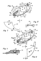
- Fig. 3 is a perspective view of a disc cutter member integrally incorporating crop lifting ramp portions;
- Fig. 4 is an enlarged top plan view of the disc cutter member seen in Fig. 3; the position of one of the knives being shown in phantom;
- Fig. 5 is a cross-sectional view of the disc cutter member seen in Fig. 4 taken along lines 5-5;
- Fig. 6 is a perspective view of a disc cutter member similar to the view of Fig. 3 but with the ramp portions being equipped with replaceable wear members;
- Fig. 7 is a top plan view of one of the wear members seen in Fig. 6;
- Fig. 8 is a peripheral side elevational view of the wear member seen in Fig. 7, corresponding to lines 8-8;
- Fig. 9 is a perspective view of a disc cutter member similar to the view seen in Fig. 6, but with the ramp portions being equipped with an alternative embodiment of a replaceable wear member;
- Fig. 10 is a top plan view of the wear member seen in Fig. 9; and
- Fig. 11 is a trailing side elevational view of the wear member corresponding to lines 11-11 of Fig. 10.
- Referring now to the drawings, and particularly to Fig. 1, a top plan view of a hay harvesting machine, commonly referred to as a disc mower-conditioner can be seen. Any left and right references are used as a matter of convenience and are determined by standing at the rear of the mower-conditioner and facing in the direction of forward travel. The mower-
conditioner 10 is shown in the form of a pull-type machine having adraft member 12 pivotably connected to theframe 14 of themachine 10. Theframe 14 includes a maintransverse support beam 15 to which are connected downwardly dependinglegs 17mounting wheels 18 for mobilely supporting themachine 10 over the ground, as best seen in Fig. 2. - Referring to Figs. 1 and 2, the mower-
conditioner 10 includes acrop harvesting header 20 floatingly supported for movement over the ground and relative to theframe 14 by thecounter balancing mechanism 22 and upper andlower links header 20 and theframe 14. Theheader 20 is provided with acrop cutting mechanism 25, seen in the form of adisc cutterbar 26, such as a Kuhn three meter, six rotor rotary cutterbar, having a plurality of transversely spaceddisc cutters 28 operable to sever standing crop material by an impact action. Aconditioning mechanism 30 is mounted in theheader 20 rearwardly of thecutting mechanism 25 to receive and condition crop material severed by thecutterbar 26. - The
conditioning mechanism 30 included a pair of cooperable, generally vertically spacedtransverse conditioning rolls roll header side sheets 21 such that the axis of rotation 33 of theupper conditioning roll 32 is spaced slightly forwardly of the axis ofrotation 35 of thelower conditioning roll 34, so that thenip 37 formed therebetween is facing slightly downwardly toward thedisc cutterbar 26. The preferred embodiment of the conditioning roll construction shown in Figs. 1 and 2 is of the intermeshing lug design. Aconventional drive mechanism 39 provides a source of rotational power to both thedisc cutterbar 26 and theconditioning mechanism 30. - Referring now to Figs. 3-5, the
disc cutters 28 can best be seen. Although the transversely opposedendmost disc cutters 28, as best seen in Figs. 1 and 2, are provided with atruncated cone 29 to provide a more aggressive crop conveying action, each of the remaininginterior disc cutters 28 will have a construction as shown in Figs. 3-5. Eachdisc member 70 of theinterior disc cutters 28 includes a raisedcentral portion 71 in which are formed recessedmounting holes 72 for connection of thedisc 70 to a driving member (not shown) in a conventional manner. The axis of rotation 73' of thedisc member 70 is positioned in the center of the raisedcentral portion 71. The oval-shaped disc member 70 is defined by a circumferentialperipheral edge 74. Circumferentially opposed along the major axis of the oval-shaped disc member 70 areknife mounting holes 77 formed in lower trench-like portions 76 defining abottom plane 81 of thedisc member 70 disposed below anupper plane 73 defined by the raisedcentral portion 71. - The
knife mounting holes 77 are provided withprotection collars 78 having acountersunk opening 79 formed therein to provide greater protection for theknife mounting hardware 47. Eachdisc member 70 is provided with a pair of diametrically opposedknives 45 detachable connected to theknife mounting portions 76 by fasteners. Upon rotation of thedisc member 70, theknives 45 sever standing crop material by an impact action. - Each
disc member 70 is provided with lowerperipheral portions 82 at circumferentially opposed positions along the minor axis of thedisc member 70. The lowerperipheral portions 82 are displaced 90 degrees around thecircumference 74 of thedisc member 70 from the knife mounting holes 77. The lowerperipheral portions 82 are positioned generally at the same level as thebottom plane 81 of thetrench portions 76. From each lowerperipheral portion 82, aninclined ramp 75 extends toward eachknife mounting hole 77. Eachinclined ramp 75 terminates in a raised trailingedge 84 extending to or near the level of theupper plane 73 defined by the raisedcentral portion 71. The trailingedges 84 can be positioned slightly below theupper plane 73 to accommodate the attachment ofwear plates 90, as will be described in further detail below with respect to Figs. 6-11. Thevertical sides 86 extend from the trailingedges 84 downwardly to thebottom plane 81, thereby defining the sides of thetrench portion 76, to lend additional protection to theknife mounting hardware 47. - The inclined ramps 75 provide a more or less aggressive lifting action to previously severed crop material to lift such material from the zones immediately trailing the cutting zones of the corresponding
knives 45. This lifting action helps prevent severed crop material from passing beneath theconditioning mechanism 30 and also helps to feed the severed crop material into thenip 37 of the conditioning rolls 32, 34 to effect a conditioning thereof. - Since each
disc member 70 is provided with four opposingly directed liftingramps 75, one skilled in the art will readily realize that thesedisc members 70 can be mounted on thecutterbar 26 for rotation in either the clockwise or counterclockwise direction during operation. With the lifting ramps 75 extending for substantially an entire quadrant of theperipheral edge 74 of thedisc members 70, thedisc members 70 will impart a balanced lifting action to the severed crop material which still is sufficiently aggressive to clear the cutting paths for the associatedknives 45. - As can be seen in Figs. 6-11, each
disc member 70 can be provided withwear plates 90 affixed to the leading lifting ramps 75, when viewed in the direction of rotation indicated by thearrow 89. As best seen in Figs. 6-8, one embodiment of thewear plates 90 will comprise a pork-chop-shaped flat plate affixed to each leading liftingramp 75 byfasteners 92 engaged withappropriate holes 94 formed in the lifting ramps 75. Since the leadingramps 75 will be subjected to the greatest amount of abrasive wear during operation of thedisc members 70, the utilization ofreplaceable wear plates 90 will provide a greater economic and operative life for thesedisc members 70. As indicated above with respect to Fig. 5, the trailingedges 84 of the lifting ramps 75 position the resulting trailingedges 94 of thewear plates 75 in substantially thesame plane 73 as the raisedcentral portion 71 of thedisc members 70. - An alternative embodiment of the
wear plate 90 can be seen in Figs. 9-11. Thiswear plate 90 includes a generally vertically extendingapron 96 positioned along the peripheral edge of thewear plate 90. Theapron 96 would present a solid face to the severed crop material to be lifted by theramps 75, upon rotation of thedisc member 70 to prevent crop material and/or other debris from being jammed underneath the liftingramp 75 and also to protect thevertical sides 86 of thetrench portion 76 from abrasive wear. - Aspects of the rotary cutting mechanism described herein are claimed in the co-pending patent application EP-A-0.158.389.
Claims (9)
Applications Claiming Priority (2)
| Application Number | Priority Date | Filing Date | Title |
|---|---|---|---|
| US06/592,643 US4531349A (en) | 1984-03-23 | 1984-03-23 | Rotary cutter for disc mower-conditioner |
| US592643 | 2000-06-13 |
Publications (2)
| Publication Number | Publication Date |
|---|---|
| EP0157453A1 EP0157453A1 (en) | 1985-10-09 |
| EP0157453B1 true EP0157453B1 (en) | 1988-09-07 |
Family
ID=24371499
Family Applications (1)
| Application Number | Title | Priority Date | Filing Date |
|---|---|---|---|
| EP85200418A Expired EP0157453B1 (en) | 1984-03-23 | 1985-03-19 | Rotary cutter mechanism |
Country Status (3)
| Country | Link |
|---|---|
| US (1) | US4531349A (en) |
| EP (1) | EP0157453B1 (en) |
| DE (1) | DE3564746D1 (en) |
Families Citing this family (25)
| Publication number | Priority date | Publication date | Assignee | Title |
|---|---|---|---|---|
| US5272859A (en) * | 1992-04-14 | 1993-12-28 | Hay & Forage Industries | Mechanical drive center pivot mower conditioner |
| US5433064A (en) | 1994-04-28 | 1995-07-18 | Hay & Forage Industries | Rotary cutter bed harvester with non-auger conveying means for outboard cutters |
| US5463852A (en) | 1994-04-28 | 1995-11-07 | Hay & Forage Industries | Wide cut harvester having rotary cutter bed |
| US5715663A (en) * | 1995-06-26 | 1998-02-10 | New Holland North America, Inc. | Crop mover for rotary disc cutter |
| DE29517559U1 (en) * | 1995-11-06 | 1996-01-25 | H. Niemeyer Söhne GmbH & Co KG, 48477 Hörstel | Disc mower |
| AU715028B2 (en) * | 1996-11-12 | 2000-01-13 | Ronald George Bird | Vertical-axis mower and roller conditioner |
| AUPO359796A0 (en) * | 1996-11-12 | 1996-12-05 | Bird, Ronald George | Cutter apparatus |
| FR2756135B1 (en) * | 1996-11-26 | 1999-01-29 | Agram | DISC OF MOWER AND MOWER CONDITIONER |
| US5845468A (en) * | 1997-06-26 | 1998-12-08 | Deere & Company | Rotary mower cutter disc having replaceable knife mount shield |
| US5842330A (en) * | 1997-07-18 | 1998-12-01 | Deere & Company | Cutterbar having cutting discs equipped for converging crop |
| USD449053S1 (en) | 1997-12-19 | 2001-10-09 | Kuhn, S.A. | Reinforced mower blade and reinforced mower blade with lid |
| US6158201A (en) * | 1998-09-15 | 2000-12-12 | Hay & Forage Industries | Rotary mower conditioner having improved cut crop flow |
| USD449623S1 (en) | 1998-12-14 | 2001-10-23 | Kuhn, S.A. | Disk for mower blades |
| USD449313S1 (en) | 1999-02-15 | 2001-10-16 | Kuhn, S.A. | Mower element |
| FR2774853B1 (en) * | 1999-02-15 | 2001-02-16 | Kuhn Sa | CUTTING MEMBER FOR A CUTTING MACHINE, PARTICULARLY A MOWER |
| US6311463B1 (en) * | 2000-03-14 | 2001-11-06 | Deere & Company | Rotary mower cutter disc having self-cleaning knife mount shield |
| DE10018391A1 (en) * | 2000-04-13 | 2001-10-25 | Krone Bernard Maschf Gmbh | mower |
| GB2460354B (en) * | 2005-08-09 | 2010-05-26 | Sandvik Intellectual Property | Stump grinding disk |
| US7100651B1 (en) * | 2005-08-09 | 2006-09-05 | Sandvik Intellectual Property Ab | Stump grinding disk and wear strips therefor |
| US7726108B1 (en) | 2009-01-14 | 2010-06-01 | Agco Corporation | Wide cut rotary harvester having cut crop feeder mechanism |
| USD647538S1 (en) * | 2010-05-17 | 2011-10-25 | Kuhn S.A. | Disc of rotary mower |
| USD640289S1 (en) * | 2010-05-17 | 2011-06-21 | Kuhn S.A. | Disc of rotary mower |
| USD645479S1 (en) * | 2011-02-03 | 2011-09-20 | Cnh America Llc | Mower disc |
| US8695316B2 (en) * | 2011-02-21 | 2014-04-15 | Agco Corporation | Fixed rotary knife with multiple cutting surfaces |
| AT525208B1 (en) * | 2021-06-24 | 2023-02-15 | Gebrueder Busatis Ges M B H | Anti-wear device for mower discs for rotor mowers |
Family Cites Families (17)
| Publication number | Priority date | Publication date | Assignee | Title |
|---|---|---|---|---|
| FR1480616A (en) * | 1966-05-20 | 1967-05-12 | Zweegers & Zonen P J | Mower |
| US3555798A (en) * | 1967-09-02 | 1971-01-19 | Welger Geb | Mowing apparatus |
| DE1936054A1 (en) * | 1969-07-16 | 1971-01-28 | Busatis Geb | Disc mower |
| GB1326900A (en) * | 1969-12-05 | 1973-08-15 | Massey Ferguson Perkins Ltd | Mowing machines |
| US3662530A (en) * | 1970-12-15 | 1972-05-16 | Harold C Henriksen | Raking and mulching means for rotary mowers |
| DE2131598C2 (en) * | 1971-06-25 | 1982-10-14 | Maschinenfabrik Fahr Ag Gottmadingen, 7702 Gottmadingen | Rotary mower with counter-rotating cutters - has pair of compression rollers for each gap between cutters transport drums |
| US3905182A (en) * | 1974-02-13 | 1975-09-16 | Horst W Geier | Rotary mower |
| FR2282216A1 (en) * | 1974-08-23 | 1976-03-19 | Sodia Sa | Cutter mechanism for agricultural machine - has pair of horiz. cutting discs feeding horiz. lifting drum |
| NL7511970A (en) * | 1975-10-10 | 1977-04-13 | Multinorm Bv | MOWING DEVICE. |
| NL7513925A (en) * | 1975-11-28 | 1977-06-01 | Multinorm Bv | MOWING DEVICE. |
| NL7513926A (en) * | 1975-11-28 | 1977-06-01 | Multinorm Bv | MOWING DEVICE. |
| NL7604451A (en) * | 1976-04-27 | 1977-10-31 | Texas Industries Inc | MOWING MACHINE. |
| GB1583982A (en) * | 1977-04-05 | 1981-02-04 | Sperry Ltd | Improvements in or relating to harvesting machines |
| NL7705300A (en) * | 1977-05-13 | 1978-11-15 | Zweegers P | MOWING MACHINE. |
| FR2452237A1 (en) * | 1979-03-27 | 1980-10-24 | Hesston Corp | MECHANICAL MOBILE RAKER |
| FR2456461A1 (en) * | 1979-05-16 | 1980-12-12 | Kuhn Sa | ROTARY MOWER WITH TWIN CUTTERS |
| AU6260580A (en) * | 1979-09-28 | 1981-04-09 | Stephen John Barnes | Mower |
-
1984
- 1984-03-23 US US06/592,643 patent/US4531349A/en not_active Expired - Fee Related
-
1985
- 1985-03-19 DE DE8585200418T patent/DE3564746D1/en not_active Expired
- 1985-03-19 EP EP85200418A patent/EP0157453B1/en not_active Expired
Also Published As
| Publication number | Publication date |
|---|---|
| DE3564746D1 (en) | 1988-10-13 |
| EP0157453A1 (en) | 1985-10-09 |
| US4531349A (en) | 1985-07-30 |
Similar Documents
| Publication | Publication Date | Title |
|---|---|---|
| US4531349A (en) | Rotary cutter for disc mower-conditioner | |
| US4567716A (en) | Full quadrant crop lifter for disc mower-conditioners | |
| EP0074695B1 (en) | A mowing machine | |
| US3848399A (en) | Sugar cane harvesters | |
| CA2706706C (en) | Rotary disk crop harvesting header with an auger for transferring the crop | |
| US7356982B2 (en) | Crop harvesting header with rotary disks and impellers for transferring the crop inwardly to a discharge opening | |
| US8434290B2 (en) | Rotary disk crop harvesting header with an auger for transferring the crop | |
| US3673779A (en) | Harvesting machine | |
| US7461498B1 (en) | Crop harvesting header with rotary disks and converging system for forming a swath | |
| US3979889A (en) | Freely rotatable shield for rotary mower | |
| US4270338A (en) | Crop harvesting machine | |
| CA2228814C (en) | Cutterbar having cutting discs equipped for converging crop | |
| PL183610B1 (en) | Machine for mowing and chaffing maize and other cauline cultivable plants irrespective of rows | |
| EP0158389B1 (en) | Crop lifter for rotary cutting mechanism | |
| US5715663A (en) | Crop mover for rotary disc cutter | |
| EP0240086B1 (en) | Self-cleaning disc cutter rotor assembly | |
| US4499711A (en) | Deflector panel for disc mower-conditioner | |
| US4711074A (en) | Mowing and chopping machine | |
| CA2531189A1 (en) | Blade for a crop harvesting header with rotary disks | |
| US4691504A (en) | Rotary mower for a tractor | |
| US5884461A (en) | Disk mower | |
| US20060213170A1 (en) | Blade for a crop harvesting header with rotary disks | |
| US4348857A (en) | Rotary mower conditioner | |
| CA1168455A (en) | Apparatus for cutting crop | |
| US6205752B1 (en) | Rolling crop guide for disc mower conditioners |
Legal Events
| Date | Code | Title | Description |
|---|---|---|---|
| PUAI | Public reference made under article 153(3) epc to a published international application that has entered the european phase |
Free format text: ORIGINAL CODE: 0009012 |
|
| 17P | Request for examination filed |
Effective date: 19850319 |
|
| AK | Designated contracting states |
Designated state(s): DE FR GB |
|
| RAP1 | Party data changed (applicant data changed or rights of an application transferred) |
Owner name: NEW HOLLAND INC. |
|
| 17Q | First examination report despatched |
Effective date: 19870514 |
|
| GRAA | (expected) grant |
Free format text: ORIGINAL CODE: 0009210 |
|
| RAP1 | Party data changed (applicant data changed or rights of an application transferred) |
Owner name: FORD NEW HOLLAND, INC. (A DELAWARE CORP.) |
|
| AK | Designated contracting states |
Kind code of ref document: B1 Designated state(s): DE FR GB |
|
| REF | Corresponds to: |
Ref document number: 3564746 Country of ref document: DE Date of ref document: 19881013 |
|
| ET | Fr: translation filed | ||
| PLBE | No opposition filed within time limit |
Free format text: ORIGINAL CODE: 0009261 |
|
| STAA | Information on the status of an ep patent application or granted ep patent |
Free format text: STATUS: NO OPPOSITION FILED WITHIN TIME LIMIT |
|
| 26N | No opposition filed | ||
| PGFP | Annual fee paid to national office [announced via postgrant information from national office to epo] |
Ref country code: DE Payment date: 19920111 Year of fee payment: 8 |
|
| PGFP | Annual fee paid to national office [announced via postgrant information from national office to epo] |
Ref country code: FR Payment date: 19920114 Year of fee payment: 8 |
|
| PGFP | Annual fee paid to national office [announced via postgrant information from national office to epo] |
Ref country code: GB Payment date: 19920311 Year of fee payment: 8 |
|
| PG25 | Lapsed in a contracting state [announced via postgrant information from national office to epo] |
Ref country code: GB Effective date: 19930319 |
|
| GBPC | Gb: european patent ceased through non-payment of renewal fee |
Effective date: 19930319 |
|
| PG25 | Lapsed in a contracting state [announced via postgrant information from national office to epo] |
Ref country code: FR Effective date: 19931130 |
|
| PG25 | Lapsed in a contracting state [announced via postgrant information from national office to epo] |
Ref country code: DE Effective date: 19931201 |
|
| REG | Reference to a national code |
Ref country code: FR Ref legal event code: ST |