EP0155982B1 - Authenticator device - Google Patents
Authenticator device Download PDFInfo
- Publication number
- EP0155982B1 EP0155982B1 EP84108691A EP84108691A EP0155982B1 EP 0155982 B1 EP0155982 B1 EP 0155982B1 EP 84108691 A EP84108691 A EP 84108691A EP 84108691 A EP84108691 A EP 84108691A EP 0155982 B1 EP0155982 B1 EP 0155982B1
- Authority
- EP
- European Patent Office
- Prior art keywords
- reflectivity
- card
- location
- data
- sheet medium
- Prior art date
- Legal status (The legal status is an assumption and is not a legal conclusion. Google has not performed a legal analysis and makes no representation as to the accuracy of the status listed.)
- Expired - Lifetime
Links
Images

Classifications
-
- G—PHYSICS
- G06—COMPUTING; CALCULATING OR COUNTING
- G06K—GRAPHICAL DATA READING; PRESENTATION OF DATA; RECORD CARRIERS; HANDLING RECORD CARRIERS
- G06K19/00—Record carriers for use with machines and with at least a part designed to carry digital markings
- G06K19/06—Record carriers for use with machines and with at least a part designed to carry digital markings characterised by the kind of the digital marking, e.g. shape, nature, code
- G06K19/08—Record carriers for use with machines and with at least a part designed to carry digital markings characterised by the kind of the digital marking, e.g. shape, nature, code using markings of different kinds or more than one marking of the same kind in the same record carrier, e.g. one marking being sensed by optical and the other by magnetic means
- G06K19/083—Constructional details
- G06K19/086—Constructional details with markings consisting of randomly placed or oriented elements, the randomness of the elements being useable for generating a unique identifying signature of the record carrier, e.g. randomly placed magnetic fibers or magnetic particles in the body of a credit card
-
- G—PHYSICS
- G06—COMPUTING; CALCULATING OR COUNTING
- G06K—GRAPHICAL DATA READING; PRESENTATION OF DATA; RECORD CARRIERS; HANDLING RECORD CARRIERS
- G06K19/00—Record carriers for use with machines and with at least a part designed to carry digital markings
- G06K19/06—Record carriers for use with machines and with at least a part designed to carry digital markings characterised by the kind of the digital marking, e.g. shape, nature, code
- G06K19/08—Record carriers for use with machines and with at least a part designed to carry digital markings characterised by the kind of the digital marking, e.g. shape, nature, code using markings of different kinds or more than one marking of the same kind in the same record carrier, e.g. one marking being sensed by optical and the other by magnetic means
- G06K19/10—Record carriers for use with machines and with at least a part designed to carry digital markings characterised by the kind of the digital marking, e.g. shape, nature, code using markings of different kinds or more than one marking of the same kind in the same record carrier, e.g. one marking being sensed by optical and the other by magnetic means at least one kind of marking being used for authentication, e.g. of credit or identity cards
-
- G—PHYSICS
- G07—CHECKING-DEVICES
- G07F—COIN-FREED OR LIKE APPARATUS
- G07F7/00—Mechanisms actuated by objects other than coins to free or to actuate vending, hiring, coin or paper currency dispensing or refunding apparatus
- G07F7/08—Mechanisms actuated by objects other than coins to free or to actuate vending, hiring, coin or paper currency dispensing or refunding apparatus by coded identity card or credit card or other personal identification means
- G07F7/086—Mechanisms actuated by objects other than coins to free or to actuate vending, hiring, coin or paper currency dispensing or refunding apparatus by coded identity card or credit card or other personal identification means by passive credit-cards adapted therefor, e.g. constructive particularities to avoid counterfeiting, e.g. by inclusion of a physical or chemical security-layer
Definitions
- This invention relates to authenticator devices of the kind for verifying the authenticity of a product, person, document or other subject, in which a sheet medium has a region that occupies at least part of the sheet and includes particles distributed therein for providing variation from one location to another within the region of response to incident light, and there is associated with the sheet medium a machine-readable representation of this response as measured at one specific location at least, of the region.
- An authenticator device of this specified kind is already known from German Patent Specification No 28 29 778 A1, in the form of a credit card having a region, notably a signature area of the card, that includes a fluorescent line.
- the line is formed by a random distribution of coarse-grained fluorescent pigments which fluoresce in response to light of a certain wavelength incident on the line.
- the fluorescent emission from the particles varies from one location to another along the line in accordance with the random distribution of the particles. In this respect, light is emitted only from the randomly-distributed pigments, and not from the spaces between them, or where the fluorescent line has been, for example, overwritten with the cardholder's signature.
- photoelectric sensing of the light emission along the line produces a test signal that varies in a manner uniquely characteristic of the card, and this signal can be compared with an associated record of an earlier sensing of the same card for the purpose of verifying the integrity of the card.
- an authenticator device of the specified kind is characterised in that the machine-readable representation is borne by the sheet medium, that the response to incident light is produced by a reflecting surface of the sheet medium, that the particles are sand-like particles carried by the reflecting surface, and that the sand-like particles modify the measurable reflectivity from one location to another within said region by obscuring the reflecting surface.
- German patent specification refers to reflection in the context of the light emitted from the fluorescent particles of the known authenticator device, a reflecting surface is not involved in that case, and the variation in response to the incident light arises from fluorescence rather than from reflectivity.
- the reflecting surface may be provided readily by a layer of foil on the sheet medium.
- the sheet material which may be of paper or other, paper-like material, may have a translucency that varies from one location to another of the device outside the region involving the sand-like particles, and may then bear a machine-readable representation of the translucency as measured at specific ones of such locations.
- the representation of translucency may be used as a further basis for verification of the authenticator device of the present invention; authenticator devices utilizing translucency as a criterion for verification are described and claimed in Applicant's European Patent No 0 054 071 (from which the present patent application is divided).
- Production of the authenticator device may be carried out using a method which includes the steps of specifying at least one location of the region, measuring the reflectivity at that location, and then recording a representation of the measure of reflectivity obtained, on the sheet medium.
- Data in accordance with the measure of reflectivity may be cryptographically encoded before being recorded, and the method may also include the step of recording data indicative of the location to which the measure of reflectivity relates.
- Verification of the authenticator device may be carried out by a method that includes the steps of machine-reading from the device the representation of measured reflectivity, freshly measuring the reflectivity at one specific location at least, of the region that includes the particles, and then comparing the freshly-obtained measure of reflectivity with the representation read out from the device.
- the location or locations from which the fresh measure or measures of reflectivity are obtained may be determined by data read from the device.
- the medium of the authenticator device of the present invention may for example, comprise part of a product, part of a tag attached to a product, part of an identification device, part of a document of value, and so on.
- the device may be implemented so that only a portion of the medium is utilized, and the location of that select portion is preserved in secrecy along with the measured reflectivity characteristic.
- the device may be variously implemented using different media and techniques.
- the reflectivity characteristic representation may, for example, be cryptographically encoded by a computer apparatus, and may be recorded optically or magnetically on the authenticator medium.
- the present invention can be effectively used to implement a reliable identification card 210 as illustrated in FIGURE 1, to which reference will now be made.
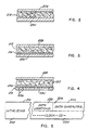
- the card 210 is a laminate article incorporating a basic sheet, e.g. bond paper 215 (see FIGURES 1, 2 and 3), along with certain other media for verification indications.
- a basic sheet e.g. bond paper 215 (see FIGURES 1, 2 and 3)
- the card 210 (FIGURE 1)
- it is adapted for use as a form of personal identification.
- certain of the aspects as disclosed herein may be readily adopted for use in a wide variety of documents including passports, valuable paper, authenticators, and so on.
- the card 210 carries print 212 (upper left) indicating the name of the assigned holder along with a photographic likeness 214 (right).
- the print 212 and the likeness 214 may be variously deposited or printed on a sheet of bond paper 215 (FIGURE 2).
- the print 212 and the likeness 214 alter the translucency of the bond paper 215 in certain specific areas. In general, overlays, erasures or other modifications of the print 212 or the likeness 214 will tend to further alter the translucency of the paper 215 at points of alteration.
- the translucency of predetermined areas involving the print 212 or the likeness 214 is sensed and provided as a record for authenticating the card 210. Indications of the translucency (or various other random characteristics, measurable but not practically duplicable) are carried on the card in a form that is not generally humanly readable. Specifically, in the authenticator embodiment of FIGURE 1, the verification confirmation information is recorded on a magnetic stripe 216 which may also provide various other information.
- the magnetic stripe 216 incorporates a clock track which not only indexes another magnetic track of the stripe 216 but additionally indexes non-magnetic areas of the card 210 for critical characteristic observations.
- the characteristic observations include translucency.
- the card 210 incorporates a stripe or band 218 for indicating still another characteristic.
- the band 218 provides dimensional reflectivity variations as a characteristic imposing an exceedingly severe burden for any effort at duplication.
- the card 210 might be carried by the assigned holder for identification. An initial confirmation of the holder could be made simply by comparing the likeness 214 on the card with the holder's physical appearance. Confirmation of the card 210 and the absence of modification would then be checked by an apparatus constructed in accordance with the present invention as described in detail below. Generally, checking is performed by scanning the card horizontally along several paths. Specifically, the card 210 is scanned for translucency readings along paths 220 and 222 (translucency tracks 1 and 2) for characteristic data indicative of the bond paper 215 in composite with the print 212 or the likeness 214. Additionally, the card 210 is scanned along the magnetic stripe 216 to obtain confirmatory data. The data from the magnetic stripe designates selected locations along the paths 220 and 222 for translucency observations. The data may also indicate the values of prior observations as well as personal identification data for a subject or holder and data on the extent or limits of use of the card.
- the structure of the card 210 includes means for a further confirmation of the authenticity, and is therefore adapted for exceedingly high reliability.
- the card 210 incorporates a band 218 (reflectivity stripe) in the form of a layer of foil 224 (FIGURE 4) carrying sand-like particles 226.
- the observed characteristic of the band 218 involves light reflectivity at particular locations. Data indicative of such characteristics are confirmed by apparatus somewhat similar to that employed for confirming the propriety of the translucency observation as mentioned above.
- the full area of the card is occupied by the bond pager 215 (FIGURES 1, 2 and 3) and a pair of external clear plastic sheet laminates 228 and 230.
- the laminates 228 and 230 also enclose the magnetic stripe 216 and the reflectivity band 218.
- techniques for the production of laminate identification cards incorporating stripes, e.g., magnetic stripes, are well known.
- the magnetic stripe 216 involves two recording tracks as well known in the prior art.
- additional tracks may be incorporated in alternative embodiments.
- One of the magnetic recording tracks is a dedicated clock track while the other track carries the following data: the locations of select characteristic areas along the paths 220 and 222; location data for the reflectivity stripe or band 218; values of the characteristics at the specified locations; and optional data including personal identification numbers, account numbers, use records, and so on.
- data locations D1 and D2 are assigned in the translucency track 1 (path 220) and locations D3 and D4 (similarly indicated) are assigned in the translucency track 2 (path 222). Again, these locations are indicated by an "X" symbol on the drawing.
- data locations D5 and D6 are assigned in the reflectivity band 218. Accordingly, the preliminary processing of the card would involve sensing the characteristic translucency at data locations D1, D2, D3, and D4 and the reflectivity at locations D5 and D6. Data indicating the locations (encoded if desired) along with the observed values of translucency and reflectivity is encoded on the magnetic stripe 216.
- a preliminary visual observation might be made concerning the likeness 214 and the identification of the print 212. If such indicators appear satisfactory, machine verification may be pursued to indicate the possibility of either a counterfeit card or an altered card. Specifically, the measurable but not substantially duplicable characteristics at locations D1, D2, D3, D4, D5, and D6 are sensed and compared with the data registered from a prior sensing of such locations. If the card 210 has been modified (as in the likeness 214) or is a forgery, on a statistical basis, it is exceedingly unlikely that the comparative standard will be attained. For even further confirmation regarding tie propriety of the card holder, a personal identification number test, may be incorporated in the magnetic stripe 218 as well known in the prior art.
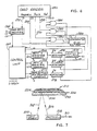
- the initial portion of the magnetic stripe 216 is dedicated to initializing the operation in cooperation with a magnetic card reader. Accordingly, an initializing section 232 occupies the leading edge of the stripe (left as illustrated). Beyond the initializing section 232, the lower portion of the stripe 216 records clock signals CS in a track 234 while the upper portion records data in a track 236.
- the first section 238 of the data track 236 specifies the data locations D1-D6 of interest for the card.
- a section 240 for recording the data characters i.e. the characteristics sensed at the locations D1-D6.
- the data in the magnetic location 238 and the clock track 234 locate the points or locations D1-D6 for sensing.
- the characteristics observed at such points or locations on the card 210 are then compared with recorded data characters provided from the section 240 which were recorded at the time of the initial sensing.
- the comparison will either indicate the card's authenticity or failure of confirmation. Consideration will now be directed to the structure of FIGURE 6 which performs the test as generally indicated above.
- a card reader 250 may take any of a variety of forms for sensing the data as described above from the card 210 (FIGURE 1). Specifically, the card reader 250 incorporates: (1) apparatus for sensing translucency along the paths 220 and 222, (2) structure for reading the magnetic stripe 216 as well known in the prior art, (3) apparatus for sensing reflectivity along the band 218, and (4) an analog-to-digital converter to convert observed analog translucency and reflectivity readings to a digital format. A form of reflectivity sensing apparatus is disclosed in detail below.
- the card 210 may be automatically moved through the card reader 250.
- the card reader 250 may be a manually operated sensing device wherein a person simply pushes the card 210 through an elongate slot. A form of the latter device for sensing a magnetic stripe is disclosed in U. S. Patent No 3,914,789 (Cocker, Jr. et al).
- the outputs from the card reader 250 include: signals D and CS representative of data and clock signals from the magnetic stripe 216 (carried on lines 252 and 254); data representative of the translucency along paths 220 and 222 (carried in lines 256 and 258); and a reflectivity signal sensed along the band 218 (carried in line 260).
- the clock signals CS (line 254) are applied to a control unit 262 for developing refined clock signals C.
- the clock signals C are supplied to each of the functional components of the system; however, in the interest of simplification, connection lines are not illustrated.
- the operating sequence of the system of FIGURE 6 is controlled and regulated by timing signals t1-t4 from the control unit 262 along with the clock signals C.
- the timing signals t1-t4 are developed by the control unit 262, using the clock signals C and the data signals D.
- the binary timing signal t1 is applied to a card data register 264.
- the register 264 receives the record from the data track 236 (FIGURE 5).
- the magnetic data stripe information may vary as suggested above; however, the portion thereof pertinent to the embodiment of FIGURE 6 is utilized to specify the locations D1-D6 and the characteristic measurements at such locations.
- the data locations from the section 238 (FIGURE 5) are specified by signals applied from the register 264 to the control unit 262 during timing signal t2.
- Some decoding may be performed on the data location signals; however, depending upon the format employed, any of a variety of specific signals may be supplied from the control unit 262 during tie interval of binary timing signal t2, to specify the data locations D1-D6.
- Signals representative of the locations D1 and D2 are provided from the control unit 262 to a register 266.
- location signals for the recording path 222 are placed in a register 268 and location signals for the reflectivity band 218 are provided in a register 270.
- the register 266 contains two values to indicate the locations D1 and D2 of the translucency track 1, i.e., path 220.
- the register 268 contains values indicative of the locations D3 and D4 on the translucency track 2, i.e., path 222.
- the register 270 holds values representative of the locations D5 and D6 along the reflectivity band 218.
- the values from the registers 266, 268, and 270 are tested against the accumulated values in a clock pulse counter 272 to indicate the instants when the locations D1-D6 are being sensed to thereby command selection of the current values detected from the sensing as the selected data characters.
- the instant position of the card 210 (as it is sensed in the card reader 250) is manifest by a location counter 272 which receives clock pulses during the timing interval of the signal t3. Essentially, the tally or accumulated count in the counter 272 indicates the relative displacement of a card 210 in the card reader 250, thereby indicating the position of the sensing apparatus with respect to the locations D1-D6.
- the accumulated count value from the location counter 272 is applied to digital coincidence detectors 274, 276, and 278 which also receive timing signals t3 and signal-represented values from the registers 266, 268, and 270.
- each detector 274, 276, and 278 Upon detecting a coincidence between received sets of signals, each detector 274, 276, and 278 provides the high level of a binary output signal to qualify a gate indicating that a critical location (D1, D2, D3, D4, D5, or D6) is currently being sensed and the representative signal is to be gated for consideration.
- Output signals from the detectors 274, 276, and 278 are connected respectively to "and" gates 280, 282, and 284.
- the "and” gates 280 and 282 receive the translucency signals in lines 256 and 258 respectively and are qualified at the critical point in time (space) to supply the observed values at the locations D1, D2, D3, and D4 (see FIGURE 1).
- the "and” gate 284 receives the reflected signal value and is qualified at the instants for observation of locations D5 and D6.
- the signals manifesting observations from the locations D1-D6 are supplied from the "and" gates 280, 282, and 284 to a comparator 288 which is also connected to receive signals from the register 264 representative of the data characters from section 240 (FIGURE 5) of the magnetic stripe 218.
- the comparator 288 receives six signal-represented values digitally representative of prior observations of the select characteristics at locations D1-D6 from the register 264.
- the comparator 288 also receives fresh data of the same nature from a current sensing of the card 210 through the gates 280, 282, and 284.
- the comparator 288 compares the two sets of data (recorded and fresh) in accordance with a predetermined logic pattern and utilizes the comparison on a statistical basis for indicating the authenticity of the card in question as described in detail above.
- the authenticator 288 may utilize a variety of comparative techniques. If a card 210 in question is resolved to be authentic or genuine, then a lamp 290 on the comparator is illuminated. Alternately, the comparing means may simply comprise two displays or registers with the operator then making a visual observation of the degree of coincidence between freshly sensed and prerecorded values.
- the assumed card 210 With the movement of the assumed card 210 through the card reader 250, it is scanned from left to right (as illustrated) so that sensors pass over each of the horizontal sections of interest. At the outset of such scanning, the magnetic stripe 216 is sensed for an initializing operation in the control unit 262 as well known in the prior art for synchronizing the sensed clock signals CS with respect to the production of the timing clock signal C. After the brief initializing period, the clock pulses C are provided with space-related regularity throughout the balance of the card scanning operation.
- data is sensed by the card reader from the magnetic track 236 (FIGURE 5). Specifically, values are provided from the first section 238 which specify the locations D1-D6 as by a numerical count of displacement along the card. Such data, along with the characteristic data from the track 236 is set in the card data register 264.
- the control unit 262 receives the signal-represented data locations from the register 264, performs processing operations, and during the interval of the timing signal t2 sets the registers 266, 268, and 270 with two values each (in this example), which are independently supplied to the detectors 274, 276, and 278 during the interval of the timing signal t3.
- the register 266 is set with values which are measured from a timing mark on the magnetic stripe 216 to initiate the interval of timing signal t3.
- the data locations in the register 266 indicate the number of clock signals CS which lie in a horizontal path and offset the locations D1 and D2 from the starting or timing mark. Similar signal-represented values are set in the register 268 for the locations D3 and D4 as well as in the register 270 for the locations D5 and D6.
- the data values in each of the registers 266, 268, and 270 are continually compared with the incrementing number in the counter 272. That is, the counter 272 is actuated to count clock pulses C from the control unit 262 from the beginning of the timing signal t3.
- the counter 272 specifies horizontal offsets for the locations D1-D6, which may be used according to the card format.
- one of the detectors 274, 276, or 273 signifies such an occurrence by qualifying one of the gates 280, 282, or 284 with the result that the observed analog signal (translucency or reflectivity sample) is gated to the comparator 288 perhaps to represent values of:
- the translucency sensing in the system of FIGURE 6 may be as described in European Patent No 0 054 071.
- an exemplary structure is illustrated in FIGURE 7.
- the card 210 (illustrated fragmentarily) is moved transversely (to the right for example) in relation to a light source 300 which may, for example, comprise a low-power infrared laser to provide a beam 302 that is reflected front the card 210 as illustrated.
- a fragmentary or reflected beam 306 is detected by a photocell 308 which provides a representative analog signal in a conductor 310.
- the photocell 308 and the point of light incidence on the card 210 are at right angles to the motion of the card 210.
- the illustrated system is duplicated for dimensional sensing operation. Specifically, a second transverse light source and photocell reflectivity reader are placed with interchanged positional relationship to the source 300 and cell 308. In that manner, a single path is scanned from two different dimensional viewpoints. Consequently, the dimensional path has a sensed characteristic that would be substantially immune from reproduction using any known photographic or other techniques. Other reflecting techniques, as for example backscattering, may well be adopted for use in a system as disclosed herein.
Abstract
Description
- This invention relates to authenticator devices of the kind for verifying the authenticity of a product, person, document or other subject, in which a sheet medium has a region that occupies at least part of the sheet and includes particles distributed therein for providing variation from one location to another within the region of response to incident light, and there is associated with the sheet medium a machine-readable representation of this response as measured at one specific location at least, of the region.
- An authenticator device of this specified kind is already known from German Patent Specification No 28 29 778 A1, in the form of a credit card having a region, notably a signature area of the card, that includes a fluorescent line. The line is formed by a random distribution of coarse-grained fluorescent pigments which fluoresce in response to light of a certain wavelength incident on the line. The fluorescent emission from the particles varies from one location to another along the line in accordance with the random distribution of the particles. In this respect, light is emitted only from the randomly-distributed pigments, and not from the spaces between them, or where the fluorescent line has been, for example, overwritten with the cardholder's signature. Thus, photoelectric sensing of the light emission along the line, produces a test signal that varies in a manner uniquely characteristic of the card, and this signal can be compared with an associated record of an earlier sensing of the same card for the purpose of verifying the integrity of the card.
- There are disadvantages inherent in this known form of authenticator device, in particular in the use of fluorescent pigments, and it is an object of the present invention to provide an alternative form of device of the specified kind having practical and economic advantages.
- According to the present invention an authenticator device of the specified kind is characterised in that the machine-readable representation is borne by the sheet medium, that the response to incident light is produced by a reflecting surface of the sheet medium, that the particles are sand-like particles carried by the reflecting surface, and that the sand-like particles modify the measurable reflectivity from one location to another within said region by obscuring the reflecting surface.
- The use of reflectivity, and variation of this from one location to another, as the basis for establishing a unique characteristic of the device for verification purposes, is of practical advantage more especially because of simplicity and ease of provision. Although the above-mentioned German patent specification refers to reflection in the context of the light emitted from the fluorescent particles of the known authenticator device, a reflecting surface is not involved in that case, and the variation in response to the incident light arises from fluorescence rather than from reflectivity.
- An authenticator device including particles which differ in reflectivity from the base material that incorporates them, is proposed in French Patent Specification 2,324,060. However, even in this case, the verifiable characteristic is not achieved in the ready and economic way of the present invention, namely, using sand-like particles carried by a reflecting surface to modify measurable reflectivity from one location to another simply by obscuring the reflecting surface.
- The reflecting surface may be provided readily by a layer of foil on the sheet medium.
- The sheet material, which may be of paper or other, paper-like material, may have a translucency that varies from one location to another of the device outside the region involving the sand-like particles, and may then bear a machine-readable representation of the translucency as measured at specific ones of such locations. The representation of translucency may be used as a further basis for verification of the authenticator device of the present invention; authenticator devices utilizing translucency as a criterion for verification are described and claimed in Applicant's European Patent No 0 054 071 (from which the present patent application is divided).
- Production of the authenticator device may be carried out using a method which includes the steps of specifying at least one location of the region, measuring the reflectivity at that location, and then recording a representation of the measure of reflectivity obtained, on the sheet medium. Data in accordance with the measure of reflectivity may be cryptographically encoded before being recorded, and the method may also include the step of recording data indicative of the location to which the measure of reflectivity relates.
- Verification of the authenticator device may be carried out by a method that includes the steps of machine-reading from the device the representation of measured reflectivity, freshly measuring the reflectivity at one specific location at least, of the region that includes the particles, and then comparing the freshly-obtained measure of reflectivity with the representation read out from the device. The location or locations from which the fresh measure or measures of reflectivity are obtained, may be determined by data read from the device.
- The medium of the authenticator device of the present invention, may for example, comprise part of a product, part of a tag attached to a product, part of an identification device, part of a document of value, and so on. As a further aspect of the invention, the device may be implemented so that only a portion of the medium is utilized, and the location of that select portion is preserved in secrecy along with the measured reflectivity characteristic.
- The device may be variously implemented using different media and techniques. The reflectivity characteristic representation may, for example, be cryptographically encoded by a computer apparatus, and may be recorded optically or magnetically on the authenticator medium.
- An authenticator device in accordance with the present invention will now be described, by way of exemplary embodiment, with reference to the accompanying drawings, in which:
- FIGURE 1 is a plan view of an identification card in accordance with the present invention;
- FIGURES 2, 3 and 4 are sectional views taken through the card of FIGURE 1 on lines 12-12, 13-13 and 14-14 respectively;
- FIGURE 5 is a fragmentary diagrammatic view of a recording format on the card of FIGURE 1;
- FIGURE 6 is a block diagram of a system for utilizing the card of FIGURE 1; and
- FIGURE 7 is a diagrammatic view of a component of the system of FIGURE 6.
- As indicated above, a detailed illustrative embodiment of the present invention is disclosed herein. However, physical identification media, data formats, and operating systems structured in accordance with the present invention may be embodied in a wide variety of forms, some of which may be quite different from those of the disclosed embodiment. Consequently, the specific structural and functional details disclosed herein are merely representative; yet in that regard, they are deemed to afford the best embodiment for purposes of disclosure and to provide a basis for the claims herein which define the scope of the present invention.
- The present invention can be effectively used to implement a
reliable identification card 210 as illustrated in FIGURE 1, to which reference will now be made. - The
card 210 is a laminate article incorporating a basic sheet, e.g. bond paper 215 (see FIGURES 1, 2 and 3), along with certain other media for verification indications. - Considering the format of the card 210 (FIGURE 1), assume for example that it is adapted for use as a form of personal identification. Of course, certain of the aspects as disclosed herein may be readily adopted for use in a wide variety of documents including passports, valuable paper, authenticators, and so on.
- In the illustrative form, the
card 210 carries print 212 (upper left) indicating the name of the assigned holder along with a photographic likeness 214 (right). Theprint 212 and thelikeness 214 may be variously deposited or printed on a sheet of bond paper 215 (FIGURE 2). Generally, theprint 212 and thelikeness 214 alter the translucency of thebond paper 215 in certain specific areas. In general, overlays, erasures or other modifications of theprint 212 or thelikeness 214 will tend to further alter the translucency of thepaper 215 at points of alteration. - In general, in accordance herewith the translucency of predetermined areas involving the
print 212 or thelikeness 214 is sensed and provided as a record for authenticating thecard 210. Indications of the translucency (or various other random characteristics, measurable but not practically duplicable) are carried on the card in a form that is not generally humanly readable. Specifically, in the authenticator embodiment of FIGURE 1, the verification confirmation information is recorded on amagnetic stripe 216 which may also provide various other information. - In the present embodiment, the
magnetic stripe 216 incorporates a clock track which not only indexes another magnetic track of thestripe 216 but additionally indexes non-magnetic areas of thecard 210 for critical characteristic observations. The characteristic observations include translucency. Additionally, thecard 210 incorporates a stripe orband 218 for indicating still another characteristic. Specifically, theband 218 provides dimensional reflectivity variations as a characteristic imposing an exceedingly severe burden for any effort at duplication. - The
card 210 might be carried by the assigned holder for identification. An initial confirmation of the holder could be made simply by comparing thelikeness 214 on the card with the holder's physical appearance. Confirmation of thecard 210 and the absence of modification would then be checked by an apparatus constructed in accordance with the present invention as described in detail below. Generally, checking is performed by scanning the card horizontally along several paths. Specifically, thecard 210 is scanned for translucency readings alongpaths 220 and 222 (translucency tracks 1 and 2) for characteristic data indicative of thebond paper 215 in composite with theprint 212 or thelikeness 214. Additionally, thecard 210 is scanned along themagnetic stripe 216 to obtain confirmatory data. The data from the magnetic stripe designates selected locations along thepaths - The structure of the
card 210 includes means for a further confirmation of the authenticity, and is therefore adapted for exceedingly high reliability. Specifically, thecard 210 incorporates a band 218 (reflectivity stripe) in the form of a layer of foil 224 (FIGURE 4) carrying sand-like particles 226. The observed characteristic of theband 218 involves light reflectivity at particular locations. Data indicative of such characteristics are confirmed by apparatus somewhat similar to that employed for confirming the propriety of the translucency observation as mentioned above. - Considering the structural form of the
card 210 in somewhat greater detail, the full area of the card is occupied by the bond pager 215 (FIGURES 1, 2 and 3) and a pair of external clearplastic sheet laminates - In addition to sealing the
bond sheet 215, thelaminates magnetic stripe 216 and thereflectivity band 218. In general, techniques for the production of laminate identification cards incorporating stripes, e.g., magnetic stripes, are well known. - Turning now to the data format of the
card 210 of FIGURE 1, themagnetic stripe 216 involves two recording tracks as well known in the prior art. Of course, additional tracks (also as well known) may be incorporated in alternative embodiments. One of the magnetic recording tracks is a dedicated clock track while the other track carries the following data: the locations of select characteristic areas along thepaths band 218; values of the characteristics at the specified locations; and optional data including personal identification numbers, account numbers, use records, and so on. - To pursue a specific example of a card format, assume that data locations D1 and D2 (indicated by "X") are assigned in the translucency track 1 (path 220) and locations D3 and D4 (similarly indicated) are assigned in the translucency track 2 (path 222). Again, these locations are indicated by an "X" symbol on the drawing.
- Further, assume that data locations D5 and D6 are assigned in the
reflectivity band 218. Accordingly, the preliminary processing of the card would involve sensing the characteristic translucency at data locations D1, D2, D3, and D4 and the reflectivity at locations D5 and D6. Data indicating the locations (encoded if desired) along with the observed values of translucency and reflectivity is encoded on themagnetic stripe 216. - To verify a card, a preliminary visual observation might be made concerning the
likeness 214 and the identification of theprint 212. If such indicators appear satisfactory, machine verification may be pursued to indicate the possibility of either a counterfeit card or an altered card. Specifically, the measurable but not substantially duplicable characteristics at locations D1, D2, D3, D4, D5, and D6 are sensed and compared with the data registered from a prior sensing of such locations. If thecard 210 has been modified (as in the likeness 214) or is a forgery, on a statistical basis, it is exceedingly unlikely that the comparative standard will be attained. For even further confirmation regarding tie propriety of the card holder, a personal identification number test, may be incorporated in themagnetic stripe 218 as well known in the prior art. - Prior to considering the system for processing the
illustrative card 210, a preliminary consideration of the recording format on themagnetic stripe 216 will be helpful. Reference now will be to FIGURE 5. The initial portion of themagnetic stripe 216 is dedicated to initializing the operation in cooperation with a magnetic card reader. Accordingly, aninitializing section 232 occupies the leading edge of the stripe (left as illustrated). Beyond theinitializing section 232, the lower portion of thestripe 216 records clock signals CS in atrack 234 while the upper portion records data in atrack 236. - In the described embodiment, the
first section 238 of thedata track 236 specifies the data locations D1-D6 of interest for the card. Following the section 238 (left to right) in thedata track 236 is asection 240 for recording the data characters, i.e. the characteristics sensed at the locations D1-D6. In the operation of the system, the data in themagnetic location 238 and theclock track 234 locate the points or locations D1-D6 for sensing. The characteristics observed at such points or locations on thecard 210 are then compared with recorded data characters provided from thesection 240 which were recorded at the time of the initial sensing. Of course, on any selected basis of criteria, as explained above, the comparison will either indicate the card's authenticity or failure of confirmation. Consideration will now be directed to the structure of FIGURE 6 which performs the test as generally indicated above. - A card reader 250 (top left) may take any of a variety of forms for sensing the data as described above from the card 210 (FIGURE 1). Specifically, the
card reader 250 incorporates: (1) apparatus for sensing translucency along thepaths magnetic stripe 216 as well known in the prior art, (3) apparatus for sensing reflectivity along theband 218, and (4) an analog-to-digital converter to convert observed analog translucency and reflectivity readings to a digital format. A form of reflectivity sensing apparatus is disclosed in detail below. Thecard 210 may be automatically moved through thecard reader 250. Alternatively, thecard reader 250 may be a manually operated sensing device wherein a person simply pushes thecard 210 through an elongate slot. A form of the latter device for sensing a magnetic stripe is disclosed in U. S. Patent No 3,914,789 (Cocker, Jr. et al). - The outputs from the
card reader 250 include: signals D and CS representative of data and clock signals from the magnetic stripe 216 (carried onlines 252 and 254); data representative of the translucency alongpaths 220 and 222 (carried inlines 256 and 258); and a reflectivity signal sensed along the band 218 (carried in line 260). - The clock signals CS (line 254) are applied to a
control unit 262 for developing refined clock signals C. The clock signals C are supplied to each of the functional components of the system; however, in the interest of simplification, connection lines are not illustrated. - The operating sequence of the system of FIGURE 6 is controlled and regulated by timing signals t1-t4 from the
control unit 262 along with the clock signals C. The timing signals t1-t4 are developed by thecontrol unit 262, using the clock signals C and the data signals D. - After the initializing operation, the binary timing signal t1 is applied to a
card data register 264. Under the control of the signals t1 and C, theregister 264 receives the record from the data track 236 (FIGURE 5). Of course, the magnetic data stripe information may vary as suggested above; however, the portion thereof pertinent to the embodiment of FIGURE 6 is utilized to specify the locations D1-D6 and the characteristic measurements at such locations. The data locations from the section 238 (FIGURE 5) are specified by signals applied from theregister 264 to thecontrol unit 262 during timing signal t2. - Some decoding may be performed on the data location signals; however, depending upon the format employed, any of a variety of specific signals may be supplied from the
control unit 262 during tie interval of binary timing signal t2, to specify the data locations D1-D6. - Signals representative of the locations D1 and D2 (for path 220) are provided from the
control unit 262 to a register 266. Somewhat similarly, location signals for therecording path 222 are placed in aregister 268 and location signals for thereflectivity band 218 are provided in aregister 270. As a consequence, after the transfer during the interval of timing signal t2, the register 266 contains two values to indicate the locations D1 and D2 of thetranslucency track 1, i.e.,path 220. Somewhat similarly, theregister 268 contains values indicative of the locations D3 and D4 on thetranslucency track 2, i.e.,path 222. Finally, theregister 270 holds values representative of the locations D5 and D6 along thereflectivity band 218. - In essence, the values from the
registers clock pulse counter 272 to indicate the instants when the locations D1-D6 are being sensed to thereby command selection of the current values detected from the sensing as the selected data characters. - The instant position of the card 210 (as it is sensed in the card reader 250) is manifest by a
location counter 272 which receives clock pulses during the timing interval of the signal t3. Essentially, the tally or accumulated count in thecounter 272 indicates the relative displacement of acard 210 in thecard reader 250, thereby indicating the position of the sensing apparatus with respect to the locations D1-D6. - The accumulated count value from the
location counter 272 is applied todigital coincidence detectors registers detector - Output signals from the
detectors gates gates lines gate 284 receives the reflected signal value and is qualified at the instants for observation of locations D5 and D6. - The signals manifesting observations from the locations D1-D6 are supplied from the "and"
gates comparator 288 which is also connected to receive signals from theregister 264 representative of the data characters from section 240 (FIGURE 5) of themagnetic stripe 218. - As described above, the
comparator 288 receives six signal-represented values digitally representative of prior observations of the select characteristics at locations D1-D6 from theregister 264. Thecomparator 288 also receives fresh data of the same nature from a current sensing of thecard 210 through thegates comparator 288 then compares the two sets of data (recorded and fresh) in accordance with a predetermined logic pattern and utilizes the comparison on a statistical basis for indicating the authenticity of the card in question as described in detail above. Of course, theauthenticator 288 may utilize a variety of comparative techniques. If acard 210 in question is resolved to be authentic or genuine, then a lamp 290 on the comparator is illuminated. Alternately, the comparing means may simply comprise two displays or registers with the operator then making a visual observation of the degree of coincidence between freshly sensed and prerecorded values. - To consider a specific examplary operation of the system of FIGURE 5, assume the existence of a
card 210 precisely as illustrated in FIGURE 1 with the data locations D1-D6 sensed and appropriately recorded on themagnetic stripe 216 along with other specific data. Further assume that thecard 210, so recorded, is presented for authentication by an apparatus constructed in accordance with FIGURE 6. By way of example, assume the following relative characteristic values exist at the data locations:
- With the movement of the assumed
card 210 through thecard reader 250, it is scanned from left to right (as illustrated) so that sensors pass over each of the horizontal sections of interest. At the outset of such scanning, themagnetic stripe 216 is sensed for an initializing operation in thecontrol unit 262 as well known in the prior art for synchronizing the sensed clock signals CS with respect to the production of the timing clock signal C. After the brief initializing period, the clock pulses C are provided with space-related regularity throughout the balance of the card scanning operation. - After initializing, data is sensed by the card reader from the magnetic track 236 (FIGURE 5). Specifically, values are provided from the
first section 238 which specify the locations D1-D6 as by a numerical count of displacement along the card. Such data, along with the characteristic data from thetrack 236 is set in thecard data register 264. - The
control unit 262 receives the signal-represented data locations from theregister 264, performs processing operations, and during the interval of the timing signal t2 sets theregisters detectors magnetic stripe 216 to initiate the interval of timing signal t3. Essentially, the data locations in the register 266 indicate the number of clock signals CS which lie in a horizontal path and offset the locations D1 and D2 from the starting or timing mark. Similar signal-represented values are set in theregister 268 for the locations D3 and D4 as well as in theregister 270 for the locations D5 and D6. - During the interval of operation (t3) the data values in each of the
registers counter 272. That is, thecounter 272 is actuated to count clock pulses C from thecontrol unit 262 from the beginning of the timing signal t3. Thus, during the interval of the timing signal t3, thecounter 272 specifies horizontal offsets for the locations D1-D6, which may be used according to the card format. - When the
counter 272 attains a number equal to the horizontal offset for each of the locations D1-D6, one of thedetectors gates comparator 288 perhaps to represent values of:
- At the conclusion of the scanning of the
card 210, currently sensed characteristic values (3, 8, 2, 5, 2, 6) from the locations D1-D6 are registered in thecomparator 288. Also, the data from the magnetic stripe section 240 (D1-D6) are also registered in the comparator, i.e., 3, 7, 2, 5, 1, 6. During the interval t4, the two sets of data are compared for a degree of coincidence. Normally, any significant degree of coincidence between the freshly observed data and the previously observed data from the magnetic stripe will indicate that thecard 210 is genuine and authentic. The small differences indicated in the exemplary data would likely be acceptable in most applications. However, in documents as thecard 210, a higher degree of coincidence may be demanded to avoid acceptance of a modified document. In that regard, any change in the print 212 (FIGURE 1) or thelikeness 214 would likely be manifest by significant differences in the signals observed versus the signals recorded regarding the locations D1, D2, and D4. - While the above system selects the desired signals by direct gating, it will be apparent to those skilled in the art that an entire scanning of data could be sensed, sampled and converted as a basis for selective comparisons. Also, many different kinds of comparison techniques might well be employed, as for example amplitude ordering and mathematical manipulation and range comparisons, e.g., sum of squares comparisons.
- The translucency sensing in the system of FIGURE 6 may be as described in European Patent No 0 054 071. As for the reflectivity sensing, an exemplary structure is illustrated in FIGURE 7. Specifically, the card 210 (illustrated fragmentarily) is moved transversely (to the right for example) in relation to a
light source 300 which may, for example, comprise a low-power infrared laser to provide abeam 302 that is reflected front thecard 210 as illustrated. A fragmentary or reflectedbeam 306 is detected by aphotocell 308 which provides a representative analog signal in aconductor 310. Note that in the plane of the drawing of FIGURE 7, i.e. the plane defined by thelight source 300, thephotocell 308 and the point of light incidence on thecard 210 are at right angles to the motion of thecard 210. - As the
card 210 is effectively scanned by thebeam 302, considerable variation is imparted to thebeam 306 in view of the sand-like particles 226 which obscure thefoil 224. As a consequence, a random measurable but not practicably duplicable characteristic is provided. - In a refined embodiment of the structure of FIGURE 7 the illustrated system is duplicated for dimensional sensing operation. Specifically, a second transverse light source and photocell reflectivity reader are placed with interchanged positional relationship to the
source 300 andcell 308. In that manner, a single path is scanned from two different dimensional viewpoints. Consequently, the dimensional path has a sensed characteristic that would be substantially immune from reproduction using any known photographic or other techniques. Other reflecting techniques, as for example backscattering, may well be adopted for use in a system as disclosed herein.
Claims (10)
- An authenticator device (210 FIG. 1) for verifying the authenticity of a product, person, document or other subject, in which a sheet medium (215) has a region (218) that occupies at least part of the sheet and includes particles (226 FIG. 4) distributed therein for providing variation from one location to another within the region (218) of response to incident light, and there is associated with the sheet medium (215) a machine-readable representation (216) of this response as measured at one specific location at least (D5; D6), of the region (218), characterised in that the machine-readable representation (216) is borne by the sheet medium (215), that the response to incident light is produced by a reflecting surface (224 FIG. 4) of the sheet medium (215), that the particles are sand-like particles (226) carried by the reflecting surface (224), and that the sand-like particles (226) modify the measurable reflectivity from one location to another (D5, D6) within said region (218) by obscuring the reflecting surface (224).
- An authenticator device according to Claim 1 wherein the reflecting surface is provided by a layer of foil (224) on the sheet medium (215).
- An authenticator device according to Claim 1 or Claim 2 wherein the machine-readable representation is recorded on the sheet medium (215) in the form of a magnetic recording (216).
- An authenticator device according to any one of Claims 1 to 3 wherein the sheet material (215) has a translucency that varies from one location to another of the device outside said region (218), and the medium bears a machine-readable representation (216) of the translucency as measured at specific locations (D1-D4) of the medium (215) outside said region (218).
- An authenticator device according to any one of Claims 1 to 4 wherein the sheet medium is of paper or other, paper-like material (215).
- A method of producing an authenticator device according to any one of Claims 1 to 5 characterised in that the production method includes the steps of specifying at least one location (D5; D6) of the region (218), measuring the reflectivity at that location (D5; D6), and then recording a representation of the measure of reflectivity obtained, on the sheet medium (215).
- A method according to Claim 6 wherein data in accordance with the measure of reflectivity is cryptographically encoded before being recorded on the sheet medium (215).
- A method according to Claim 6 or Claim 7 including the step of recording on the sheet medium (215) data indicative of the location (D5; D6) to which the measure of reflectivity relates.
- A method of verification of an authenticator device according to any one of Claims 1 to 5 characterised in that the verification method includes the steps of machine-reading (252 FIG. 6) from the device (210) the said representation of measured reflectivity borne by the sheet medium (215), freshly measuring (260 FIG. 6) the reflectivity at one specific location at least (D5: D6), of said region (218), and then comparing (288 FIG. 6) the freshly-obtained measure of reflectivity (260) with the representation read out (252) from the device (210).
- A method according to Claim 9 wherein the location from which the measure of reflectivity is freshly obtained, is determined by data (270 FIG. 6) read from the device (210).
Priority Applications (1)
| Application Number | Priority Date | Filing Date | Title |
|---|---|---|---|
| AT84108691T ATE67328T1 (en) | 1980-06-23 | 1981-06-19 | AUTHENTICATION DEVICE. |
Applications Claiming Priority (2)
| Application Number | Priority Date | Filing Date | Title |
|---|---|---|---|
| US16183880A | 1980-06-23 | 1980-06-23 | |
| US161838 | 1980-06-23 |
Related Parent Applications (1)
| Application Number | Title | Priority Date | Filing Date |
|---|---|---|---|
| EP81901976.1 Division | 1982-01-12 |
Related Child Applications (1)
| Application Number | Title | Priority Date | Filing Date |
|---|---|---|---|
| EP87118167.3 Division-Into | 1987-12-08 |
Publications (2)
| Publication Number | Publication Date |
|---|---|
| EP0155982A1 EP0155982A1 (en) | 1985-10-02 |
| EP0155982B1 true EP0155982B1 (en) | 1991-09-11 |
Family
ID=22582968
Family Applications (3)
| Application Number | Title | Priority Date | Filing Date |
|---|---|---|---|
| EP81901976A Expired EP0054071B1 (en) | 1980-06-23 | 1981-06-19 | Authenticator device and related method and apparatus for production and use |
| EP87118167A Withdrawn EP0298156A3 (en) | 1980-06-23 | 1981-06-19 | Non-counterfeitable authentication card |
| EP84108691A Expired - Lifetime EP0155982B1 (en) | 1980-06-23 | 1981-06-19 | Authenticator device |
Family Applications Before (2)
| Application Number | Title | Priority Date | Filing Date |
|---|---|---|---|
| EP81901976A Expired EP0054071B1 (en) | 1980-06-23 | 1981-06-19 | Authenticator device and related method and apparatus for production and use |
| EP87118167A Withdrawn EP0298156A3 (en) | 1980-06-23 | 1981-06-19 | Non-counterfeitable authentication card |
Country Status (9)
| Country | Link |
|---|---|
| EP (3) | EP0054071B1 (en) |
| JP (1) | JPH0616312B2 (en) |
| AT (1) | ATE67328T1 (en) |
| AU (1) | AU7414281A (en) |
| BR (1) | BR8108661A (en) |
| DE (1) | DE3177255D1 (en) |
| DK (1) | DK75782A (en) |
| NO (1) | NO820552L (en) |
| WO (1) | WO1982000062A1 (en) |
Cited By (1)
| Publication number | Priority date | Publication date | Assignee | Title |
|---|---|---|---|---|
| US6328342B1 (en) | 1995-08-01 | 2001-12-11 | Boris Ilich Belousov | Tape data carrier, method and device for manufacturing the same |
Families Citing this family (35)
| Publication number | Priority date | Publication date | Assignee | Title |
|---|---|---|---|---|
| DE3038614A1 (en) * | 1980-10-13 | 1982-04-22 | Copytex-Abrechnungssysteme für Dienstleistungsautomaten GbmH, 7742 St Georgen | METHOD FOR RETURNING RETURN OF INFORMATION ENTERING ON A DATA CARRIER AND DEVICE FOR READING IN AND / OR READING OUT INFORMATION PROTECTED AGAINST RETURN TRANSFER |
| DE3043985A1 (en) * | 1980-11-21 | 1982-06-03 | Hermann 7742 St Georgen Stockburger | METHOD AND DEVICE FOR LABELING AND / OR IDENTIFYING A DATA CARRIER |
| JPS59501388A (en) * | 1982-07-15 | 1984-08-02 | ライト・シグネイチヤ−ズ,インコ−ポ−レテツド | safety system |
| FR2534712B1 (en) * | 1982-10-19 | 1986-12-26 | Traitement Information Tech Nl | METHOD FOR CERTIFYING INFORMATION PLACED ON A MEDIUM, INFORMATION MEDIUM AND APPARATUS FOR CERTIFYING MEDIA SUCH AS IDENTITY CARDS |
| DE3243758C2 (en) * | 1982-11-26 | 1985-08-22 | Brown, Boveri & Cie Ag, 6800 Mannheim | Method for increasing the protection against forgery of an identity card |
| FR2563351A1 (en) * | 1984-04-19 | 1985-10-25 | Loire Electronique | METHOD AND DEVICE FOR IDENTIFICATION AND AUTHENTICATION OF DOCUMENTS |
| US4635054A (en) * | 1985-07-10 | 1987-01-06 | Light Signatures, Inc. | Operator interactive device verification system |
| JPS63137386A (en) * | 1986-11-17 | 1988-06-09 | ライト・シグネイチヤーズ・インコーポレーテツド | Document validation system |
| US4972475A (en) * | 1987-02-10 | 1990-11-20 | Veritec Inc. | Authenticating pseudo-random code and apparatus |
| CA1293805C (en) * | 1987-02-10 | 1991-12-31 | Veritec, Inc. | Authenticating pseudo-random code and apparatus |
| DE3736882C2 (en) * | 1987-10-30 | 1997-04-30 | Gao Ges Automation Org | Method for checking the authenticity of a data carrier with an integrated circuit |
| US4924078A (en) * | 1987-11-25 | 1990-05-08 | Sant Anselmo Carl | Identification symbol, system and method |
| JPH0354664A (en) * | 1989-07-24 | 1991-03-08 | Kiyuube Kk | Guaranteeing system for expensive article such as art object or the like |
| JPH03282690A (en) * | 1990-03-29 | 1991-12-12 | Omron Corp | Card security system |
| NL9001368A (en) * | 1990-06-15 | 1992-01-02 | Tel Developments B V | SECURITY OF OBJECTS OR DOCUMENTS. |
| EP0583709B1 (en) * | 1992-08-17 | 1999-05-06 | THOMSON multimedia | Unforgeable identification device, identification device reader and method of identification |
| US5434917A (en) * | 1993-10-13 | 1995-07-18 | Thomson Consumer Electronics S.A. | Unforgeable identification device, identification device reader and method of identification |
| NL9400782A (en) * | 1994-05-11 | 1995-12-01 | Unicate Bv | Scanning device. |
| JPH08301406A (en) * | 1995-04-28 | 1996-11-19 | Japan Steel & Tube Constr Co Ltd | Throw port equipment with garbage discharge measuring device |
| LV11649B (en) * | 1996-07-15 | 1997-04-20 | Vladimir Moldovan | Identification mrthod of producer of goods |
| JP3980706B2 (en) * | 1997-05-23 | 2007-09-26 | 危機管理株式会社 | IC card and authentication device thereof |
| WO1998055970A1 (en) * | 1997-06-05 | 1998-12-10 | Dix It S.R.L. | Method for ascertaining the authenticity of a predetermined product |
| GB0009092D0 (en) * | 2000-04-13 | 2000-05-31 | Rue De Int Ltd | Recording medium and manufacturing method |
| GB0402035D0 (en) | 2004-01-30 | 2004-03-03 | Hewlett Packard Development Co | Physical object with memory tags and apparatus for writing and using such objects |
| GB2410590B (en) | 2004-01-30 | 2007-02-14 | Hewlett Packard Development Co | Physical object with memory tag and apparatus for use with such objects |
| GB0402025D0 (en) | 2004-01-30 | 2004-03-03 | Hewlett Packard Development Co | Physical object with memory tag and apparatus for use with such objects |
| JP4534561B2 (en) | 2004-04-13 | 2010-09-01 | 株式会社日立製作所 | Reliability judgment method for printed matter |
| JP4834968B2 (en) | 2004-08-11 | 2011-12-14 | 富士ゼロックス株式会社 | Authenticity determination system, authenticity determination device and program |
| JP4904690B2 (en) * | 2004-12-13 | 2012-03-28 | 富士ゼロックス株式会社 | Article management system and article management method |
| AT502714B1 (en) * | 2005-10-25 | 2012-04-15 | Binder Consulting Gmbh | METHOD FOR CREATING AND VERIFYING A SAFE CLEAR TEXT PRINT, AND DEVICE AND INFORMATION CARRIER THEREFOR |
| US7624928B2 (en) | 2005-11-18 | 2009-12-01 | Fuji Xerox Co., Ltd. | Method and apparatus for making tags, tag, and system for managing articles |
| GB0702092D0 (en) * | 2007-02-02 | 2007-03-14 | Fracture Code Corp Aps | Graphic Code Application Apparatus and Method |
| DE202008014997U1 (en) | 2008-11-12 | 2009-02-12 | Nivatex Limited | Data carrier for forming a protective mark on its surface |
| TWI386873B (en) * | 2008-12-23 | 2013-02-21 | Ik Nyeon Kim | Seal security device and system and method for determining security maintenance by reading arrangement of fine particles having random distribution contained in fine particle liquid |
| RU2661817C1 (en) * | 2017-09-12 | 2018-07-19 | Павел Анатольевич Дмитриков | Method of metallic relief image producing |
Citations (1)
| Publication number | Priority date | Publication date | Assignee | Title |
|---|---|---|---|---|
| DE2829778A1 (en) * | 1978-07-06 | 1980-01-17 | Gao Ges Automation Org | Credit or identity card carrying machine-readable information - contains paper ply with plastics coating filled with absorbent and/or scattering, scannable material |
Family Cites Families (11)
| Publication number | Priority date | Publication date | Assignee | Title |
|---|---|---|---|---|
| SE330282B (en) * | 1968-06-24 | 1970-11-09 | Saab Ab | |
| BE789503A (en) * | 1971-10-13 | 1973-01-15 | Burroughs Corp | |
| SE389413B (en) * | 1973-05-08 | 1976-11-01 | Asea Ab | CONTROL SYSTEM WITH MACHINE-READABLE PERSONAL DOCUMENTS. |
| NL7416982A (en) * | 1974-12-30 | 1976-07-02 | Koppens Automatic Fabrieken Bv | PROCEDURE FOR MANUFACTURE OF A CARD WHICH CAN BE USED AS A MEANS OF PAYMENT IN AUTOMATICS, THE CARD SO MANUFACTURED AND THE DEVICE FOR MANUFACTURING IT AS WELL AS THE Vending Machine WITH WHICH THE CARD CAN BE USED. |
| US4034211A (en) * | 1975-06-20 | 1977-07-05 | Ncr Corporation | System and method for providing a security check on a credit card |
| US4218674A (en) * | 1975-09-09 | 1980-08-19 | Dasy Inter S.A. | Method and a system for verifying authenticity safe against forgery |
| DE2635795B2 (en) * | 1975-09-09 | 1980-08-21 | Dasy Inter S.A., Genf (Schweiz) | Method and device for checking the authenticity of identification cards and similar documents |
| US4025759A (en) * | 1975-10-16 | 1977-05-24 | The Grey Lab. Establishment | Checking apparatus for documents |
| DE2826469C2 (en) * | 1978-06-16 | 1982-12-02 | The Grey Lab. Establishment, 9490 Vaduz | Procedure and device for securing documents |
| DE2847756B2 (en) * | 1978-11-03 | 1980-08-21 | Hermann 7742 St Georgen Stockburger | Procedure for the secret identification and evaluation of machine-readable data carriers |
| DE2936409A1 (en) * | 1979-09-08 | 1981-03-19 | Hermann 7742 St. Georgen Stockburger | METHOD FOR BACKING UP DATA |
-
1981
- 1981-06-19 WO PCT/US1981/000853 patent/WO1982000062A1/en not_active Application Discontinuation
- 1981-06-19 EP EP81901976A patent/EP0054071B1/en not_active Expired
- 1981-06-19 EP EP87118167A patent/EP0298156A3/en not_active Withdrawn
- 1981-06-19 AT AT84108691T patent/ATE67328T1/en not_active IP Right Cessation
- 1981-06-19 EP EP84108691A patent/EP0155982B1/en not_active Expired - Lifetime
- 1981-06-19 JP JP56502483A patent/JPH0616312B2/en not_active Expired - Lifetime
- 1981-06-19 DE DE8484108691T patent/DE3177255D1/en not_active Expired - Lifetime
- 1981-06-19 AU AU74142/81A patent/AU7414281A/en not_active Withdrawn
- 1981-06-19 BR BR8108661A patent/BR8108661A/en unknown
-
1982
- 1982-02-22 DK DK75782A patent/DK75782A/en not_active Application Discontinuation
- 1982-02-23 NO NO820552A patent/NO820552L/en unknown
Patent Citations (1)
| Publication number | Priority date | Publication date | Assignee | Title |
|---|---|---|---|---|
| DE2829778A1 (en) * | 1978-07-06 | 1980-01-17 | Gao Ges Automation Org | Credit or identity card carrying machine-readable information - contains paper ply with plastics coating filled with absorbent and/or scattering, scannable material |
Cited By (1)
| Publication number | Priority date | Publication date | Assignee | Title |
|---|---|---|---|---|
| US6328342B1 (en) | 1995-08-01 | 2001-12-11 | Boris Ilich Belousov | Tape data carrier, method and device for manufacturing the same |
Also Published As
| Publication number | Publication date |
|---|---|
| ATE67328T1 (en) | 1991-09-15 |
| EP0054071A4 (en) | 1983-08-17 |
| EP0155982A1 (en) | 1985-10-02 |
| EP0298156A2 (en) | 1989-01-11 |
| JPS57500851A (en) | 1982-05-13 |
| EP0054071A1 (en) | 1982-06-23 |
| DK75782A (en) | 1982-02-22 |
| WO1982000062A1 (en) | 1982-01-07 |
| BR8108661A (en) | 1982-05-25 |
| JPH0616312B2 (en) | 1994-03-02 |
| AU7414281A (en) | 1982-01-19 |
| DE3177255D1 (en) | 1991-10-17 |
| EP0298156A3 (en) | 1989-01-18 |
| NO820552L (en) | 1982-02-23 |
| EP0054071B1 (en) | 1985-12-04 |
Similar Documents
| Publication | Publication Date | Title |
|---|---|---|
| EP0155982B1 (en) | Authenticator device | |
| US4785290A (en) | Non-counterfeitable document system | |
| US4546352A (en) | Non-counterfeitable document system | |
| US4423415A (en) | Non-counterfeitable document system | |
| US4489318A (en) | Non-counterfeitable document system | |
| US4816657A (en) | Method and device for characterizing and identifying falsification-proof data supports | |
| US4218674A (en) | Method and a system for verifying authenticity safe against forgery | |
| US4985614A (en) | Object verification apparatus and method | |
| EP0275117B1 (en) | Verifiable object | |
| US4675669A (en) | System of issuing secure documents of various denomination | |
| US4906988A (en) | Object verification system and method | |
| JP2793366B2 (en) | Articles tagged with anti-counterfeiting and method of identifying counterfeiting of such articles | |
| US4630845A (en) | Authentication document system | |
| US4663622A (en) | Non-counterfeitable document system | |
| US5216229A (en) | Verifiable object having incremental key | |
| GB2052819A (en) | Method and means for producing and analysing secret identifying code marks in machine-scanned data carriers | |
| EP0276814A2 (en) | Object verification system and method | |
| US4656473A (en) | Secure card and sensing system | |
| CA1180814A (en) | Non-counterfeitable document system | |
| EP0660959A1 (en) | Diffraction surface data detector | |
| JPH06243304A (en) | Information recording medium provided with personal information | |
| CA1272289A (en) | Signature verification system | |
| AU673852B2 (en) | Diffraction surface data detector | |
| JPH04295985A (en) | Magnetic card and method and device for discriminating justifiability of the same | |
| JPS61137273A (en) | Recording reader of magnetic card |
Legal Events
| Date | Code | Title | Description |
|---|---|---|---|
| PUAI | Public reference made under article 153(3) epc to a published international application that has entered the european phase |
Free format text: ORIGINAL CODE: 0009012 |
|
| AC | Divisional application: reference to earlier application |
Ref document number: 54071 Country of ref document: EP |
|
| AK | Designated contracting states |
Designated state(s): AT CH DE FR GB LI LU NL SE |
|
| 17P | Request for examination filed |
Effective date: 19860401 |
|
| 17Q | First examination report despatched |
Effective date: 19880722 |
|
| RAP3 | Party data changed (applicant data changed or rights of an application transferred) |
Owner name: LIGHT SIGNATURES, INC. |
|
| GRAA | (expected) grant |
Free format text: ORIGINAL CODE: 0009210 |
|
| AC | Divisional application: reference to earlier application |
Ref document number: 54071 Country of ref document: EP |
|
| AK | Designated contracting states |
Kind code of ref document: B1 Designated state(s): AT CH DE FR GB LI LU NL SE |
|
| PG25 | Lapsed in a contracting state [announced via postgrant information from national office to epo] |
Ref country code: SE Effective date: 19910911 Ref country code: NL Effective date: 19910911 Ref country code: LI Effective date: 19910911 Ref country code: CH Effective date: 19910911 Ref country code: AT Effective date: 19910911 |
|
| REF | Corresponds to: |
Ref document number: 67328 Country of ref document: AT Date of ref document: 19910915 Kind code of ref document: T |
|
| REF | Corresponds to: |
Ref document number: 3177255 Country of ref document: DE Date of ref document: 19911017 |
|
| ET | Fr: translation filed | ||
| REG | Reference to a national code |
Ref country code: CH Ref legal event code: PL |
|
| NLV1 | Nl: lapsed or annulled due to failure to fulfill the requirements of art. 29p and 29m of the patents act | ||
| PG25 | Lapsed in a contracting state [announced via postgrant information from national office to epo] |
Ref country code: LU Free format text: LAPSE BECAUSE OF NON-PAYMENT OF DUE FEES Effective date: 19920630 |
|
| PLBE | No opposition filed within time limit |
Free format text: ORIGINAL CODE: 0009261 |
|
| STAA | Information on the status of an ep patent application or granted ep patent |
Free format text: STATUS: NO OPPOSITION FILED WITHIN TIME LIMIT |
|
| 26N | No opposition filed | ||
| PGFP | Annual fee paid to national office [announced via postgrant information from national office to epo] |
Ref country code: FR Payment date: 19960321 Year of fee payment: 16 |
|
| PGFP | Annual fee paid to national office [announced via postgrant information from national office to epo] |
Ref country code: GB Payment date: 19960325 Year of fee payment: 16 |
|
| PGFP | Annual fee paid to national office [announced via postgrant information from national office to epo] |
Ref country code: DE Payment date: 19960628 Year of fee payment: 16 |
|
| PG25 | Lapsed in a contracting state [announced via postgrant information from national office to epo] |
Ref country code: GB Free format text: LAPSE BECAUSE OF NON-PAYMENT OF DUE FEES Effective date: 19970619 |
|
| GBPC | Gb: european patent ceased through non-payment of renewal fee |
Effective date: 19970619 |
|
| PG25 | Lapsed in a contracting state [announced via postgrant information from national office to epo] |
Ref country code: FR Free format text: LAPSE BECAUSE OF NON-PAYMENT OF DUE FEES Effective date: 19980227 |
|
| PG25 | Lapsed in a contracting state [announced via postgrant information from national office to epo] |
Ref country code: DE Free format text: LAPSE BECAUSE OF NON-PAYMENT OF DUE FEES Effective date: 19980303 |
|
| REG | Reference to a national code |
Ref country code: FR Ref legal event code: ST |
|
| REG | Reference to a national code |
Ref country code: FR Ref legal event code: ST |