EP0155142A2 - Apparatus and method for remote sensing of gases, vapours or aerosols - Google Patents
Apparatus and method for remote sensing of gases, vapours or aerosols Download PDFInfo
- Publication number
- EP0155142A2 EP0155142A2 EP85301544A EP85301544A EP0155142A2 EP 0155142 A2 EP0155142 A2 EP 0155142A2 EP 85301544 A EP85301544 A EP 85301544A EP 85301544 A EP85301544 A EP 85301544A EP 0155142 A2 EP0155142 A2 EP 0155142A2
- Authority
- EP
- European Patent Office
- Prior art keywords
- radiation
- temporal coherence
- gas
- band
- aerosol
- Prior art date
- Legal status (The legal status is an assumption and is not a legal conclusion. Google has not performed a legal analysis and makes no representation as to the accuracy of the status listed.)
- Granted
Links
- 239000000443 aerosol Substances 0.000 title claims abstract description 24
- 238000000034 method Methods 0.000 title claims description 17
- 239000007789 gas Substances 0.000 title description 59
- 230000005855 radiation Effects 0.000 claims abstract description 57
- 230000002123 temporal effect Effects 0.000 claims abstract description 50
- 230000008859 change Effects 0.000 claims abstract description 15
- 239000011521 glass Substances 0.000 claims abstract description 10
- 230000003287 optical effect Effects 0.000 claims abstract description 8
- 238000010521 absorption reaction Methods 0.000 claims description 26
- 230000003595 spectral effect Effects 0.000 claims description 20
- 238000001514 detection method Methods 0.000 claims description 18
- 238000000862 absorption spectrum Methods 0.000 claims description 15
- 230000003993 interaction Effects 0.000 claims description 6
- 230000004044 response Effects 0.000 claims description 6
- 238000005259 measurement Methods 0.000 claims description 3
- 230000006798 recombination Effects 0.000 claims description 2
- 238000005215 recombination Methods 0.000 claims description 2
- 238000001228 spectrum Methods 0.000 description 28
- 238000005286 illumination Methods 0.000 description 17
- RAHZWNYVWXNFOC-UHFFFAOYSA-N Sulphur dioxide Chemical compound O=S=O RAHZWNYVWXNFOC-UHFFFAOYSA-N 0.000 description 10
- 230000000694 effects Effects 0.000 description 5
- 235000010269 sulphur dioxide Nutrition 0.000 description 5
- 239000004291 sulphur dioxide Substances 0.000 description 5
- 230000005540 biological transmission Effects 0.000 description 3
- IJGRMHOSHXDMSA-UHFFFAOYSA-N Atomic nitrogen Chemical compound N#N IJGRMHOSHXDMSA-UHFFFAOYSA-N 0.000 description 2
- 230000008033 biological extinction Effects 0.000 description 2
- 238000001914 filtration Methods 0.000 description 2
- 238000012544 monitoring process Methods 0.000 description 2
- 230000000737 periodic effect Effects 0.000 description 2
- 230000035945 sensitivity Effects 0.000 description 2
- 230000009471 action Effects 0.000 description 1
- 230000003466 anti-cipated effect Effects 0.000 description 1
- 239000003795 chemical substances by application Substances 0.000 description 1
- 238000005100 correlation spectroscopy Methods 0.000 description 1
- 230000001934 delay Effects 0.000 description 1
- 230000003111 delayed effect Effects 0.000 description 1
- 230000001419 dependent effect Effects 0.000 description 1
- 238000013461 design Methods 0.000 description 1
- 238000005516 engineering process Methods 0.000 description 1
- 239000003344 environmental pollutant Substances 0.000 description 1
- 229910052736 halogen Inorganic materials 0.000 description 1
- 150000002367 halogens Chemical class 0.000 description 1
- 238000012986 modification Methods 0.000 description 1
- 230000004048 modification Effects 0.000 description 1
- 229910052757 nitrogen Inorganic materials 0.000 description 1
- 231100000719 pollutant Toxicity 0.000 description 1
- 230000008569 process Effects 0.000 description 1
- 238000012545 processing Methods 0.000 description 1
- 238000005070 sampling Methods 0.000 description 1
- 239000000779 smoke Substances 0.000 description 1
- 239000007787 solid Substances 0.000 description 1
- 230000001360 synchronised effect Effects 0.000 description 1
- WFKWXMTUELFFGS-UHFFFAOYSA-N tungsten Chemical compound [W] WFKWXMTUELFFGS-UHFFFAOYSA-N 0.000 description 1
- 229910052721 tungsten Inorganic materials 0.000 description 1
- 239000010937 tungsten Substances 0.000 description 1
- 238000001429 visible spectrum Methods 0.000 description 1
- 229910052724 xenon Inorganic materials 0.000 description 1
- FHNFHKCVQCLJFQ-UHFFFAOYSA-N xenon atom Chemical compound [Xe] FHNFHKCVQCLJFQ-UHFFFAOYSA-N 0.000 description 1
Images


Classifications
-
- G—PHYSICS
- G01—MEASURING; TESTING
- G01N—INVESTIGATING OR ANALYSING MATERIALS BY DETERMINING THEIR CHEMICAL OR PHYSICAL PROPERTIES
- G01N21/00—Investigating or analysing materials by the use of optical means, i.e. using sub-millimetre waves, infrared, visible or ultraviolet light
- G01N21/17—Systems in which incident light is modified in accordance with the properties of the material investigated
- G01N21/25—Colour; Spectral properties, i.e. comparison of effect of material on the light at two or more different wavelengths or wavelength bands
- G01N21/31—Investigating relative effect of material at wavelengths characteristic of specific elements or molecules, e.g. atomic absorption spectrometry
- G01N21/39—Investigating relative effect of material at wavelengths characteristic of specific elements or molecules, e.g. atomic absorption spectrometry using tunable lasers
-
- G—PHYSICS
- G01—MEASURING; TESTING
- G01J—MEASUREMENT OF INTENSITY, VELOCITY, SPECTRAL CONTENT, POLARISATION, PHASE OR PULSE CHARACTERISTICS OF INFRARED, VISIBLE OR ULTRAVIOLET LIGHT; COLORIMETRY; RADIATION PYROMETRY
- G01J3/00—Spectrometry; Spectrophotometry; Monochromators; Measuring colours
- G01J3/28—Investigating the spectrum
- G01J3/45—Interferometric spectrometry
- G01J3/453—Interferometric spectrometry by correlation of the amplitudes
-
- G—PHYSICS
- G01—MEASURING; TESTING
- G01N—INVESTIGATING OR ANALYSING MATERIALS BY DETERMINING THEIR CHEMICAL OR PHYSICAL PROPERTIES
- G01N21/00—Investigating or analysing materials by the use of optical means, i.e. using sub-millimetre waves, infrared, visible or ultraviolet light
- G01N21/17—Systems in which incident light is modified in accordance with the properties of the material investigated
- G01N2021/1793—Remote sensing
- G01N2021/1795—Atmospheric mapping of gases
-
- G—PHYSICS
- G01—MEASURING; TESTING
- G01N—INVESTIGATING OR ANALYSING MATERIALS BY DETERMINING THEIR CHEMICAL OR PHYSICAL PROPERTIES
- G01N21/00—Investigating or analysing materials by the use of optical means, i.e. using sub-millimetre waves, infrared, visible or ultraviolet light
- G01N21/17—Systems in which incident light is modified in accordance with the properties of the material investigated
- G01N21/25—Colour; Spectral properties, i.e. comparison of effect of material on the light at two or more different wavelengths or wavelength bands
- G01N21/31—Investigating relative effect of material at wavelengths characteristic of specific elements or molecules, e.g. atomic absorption spectrometry
- G01N21/35—Investigating relative effect of material at wavelengths characteristic of specific elements or molecules, e.g. atomic absorption spectrometry using infrared light
- G01N21/3504—Investigating relative effect of material at wavelengths characteristic of specific elements or molecules, e.g. atomic absorption spectrometry using infrared light for analysing gases, e.g. multi-gas analysis
- G01N2021/3531—Investigating relative effect of material at wavelengths characteristic of specific elements or molecules, e.g. atomic absorption spectrometry using infrared light for analysing gases, e.g. multi-gas analysis without instrumental source, i.e. radiometric
Definitions
- the invention relates to the detection of gases and vapours or aerosols by remote or semi-remote sensing and in particular to the measurement of changes in phase and amplitude occurring at the site of interaction between illuminating energy and the remote gas, vapour or aerosol.
- gas is to be understood to include vapour or aerosol.
- the most widely used technique for remote detection is some form of correlation spectroscopy where a set of absorption bands is detected by one of the many basic types of spectrometer.
- the intensity profile of the dispersed spectrum is then modulated by a matching correlation mask, generally having alternate slits and bars, which is made to scan across the appropriate part of the optical spectrum.
- a modulated signal of specific frequency content will appear at the output of a detector arranged behind the mask.
- This technique relies upon the detection of amplitude variation of the received spectrum, ie the change in absorption is detected by a change in signal amplitude (or intensity) against a background whose amplitude profile is a very complicated structure.
- the object of the present invention is to provide a sensor and method for remote detection of gases which is capable of high sensitivity and accuracy.
- the invention comprises in one form a method for remote detection of a gas, vapour or aerosol comprising measurement of the change of temporal coherence of radiation illuminating the gas, vapour or aerosol due to absorption of radiation thereby.
- the temporal coherence of radiation of wavelengthx is inversely proportional to the spectral line widthSX.
- the spectral bandwidth of the scattered energy after passage through the target gas becomes narrower when the bandwidth overlaps an absorption feature in the gas absorption spectrum and thus the effective temporal coherence of the radiation is increased.
- the greater the narrowing of the illuminating spectrum the greater the change in temporal coherence (or coherence length) and the better the instrumentation can sense the presence of the gas etc.
- the target gas's absorption line may be altered in position relative to the illuminating spectrum.
- the optimum positions can be stated as occurring when the change of Fourier Transform of the illuminating spectrum due to the presence of the target gas is maximised.
- radiation is transmitted and after reflection by the gas, vapour or aerosol is detected by a receiver co-located with the radiation transmitter.
- the receiver maybe arranged to discriminate against the transmitted radiation, responding only to radiation of longer temporal coherence than the transmitted radiation.
- the receiver may be arranged to respond only to increases in temporal coherence within a specified band-width.
- semi-active arrangement use may be made of another illuminating souce such as sunlight or other radiation not purposefully arranged as a transmitter.
- a broadband source like the sun can be appropriately band-limited at the receiver toitnit ate a narrow-band active source.
- the invention may be used to detect a target gas etc. which is self-illuminating.
- provision may be made to spectrally scan the changes in temporal coherence or Fourier Transform.
- the invention also provides apparatus for remote sensing of a gas, vapour or aerosol comprisingin one form: a transmitter capable of emitting radiation having a spectral line or band which at least partly overlaps a feature in the absorption spectrum of the gas, vapour or aerosol; radiation collecting means for receiving radiation from a predetermined field of view; and a detector responsive to changes in the temporal coherence of the transmitted radiation caused by interaction of the radiation with the gas, vapour or aerosol.
- the transmitter is a laser which may be tuned or the laser selected such that the transmitted radiation includes a spectral line or band in a wavelength range over which the target gas, vapour or aerosol has a changing absorption profile.
- the transmitter may be replaced by a narrow-band transmission filter having a band-pass which at least partly overlaps a feature in the absorption jt ectrum of the gas, vapour or aerosol.
- the receiver may include a high pass temporal coherence filter which is insensitive to the transmitted or illuminating radiation.
- the temporal coherence filter includes an interferometer wherein received radiation is split into two beams and then recombined, one of the beams having a longer path length than the other.
- the interferometer can conveniently include a Fresnel biprism, and a glass delay plate may be placed in one of the beams.
- An amplitude modulating reticle may be placed in the path of the recombined beams and cyclically moved so as to sensitise the detector to interference fringes.
- the receiver may include a band pass temporal coherence filter with the lower band pass limit set above the temporal coherence of the transmitted or band-pass limited illuminating radiation.
- the band pass tempor al coherence filter may include a Michelson interferometer wherein the received radiation is split into two beams and then recombined with the path length of the beams being different, an optical delay being placed in a portion of one of the beams so as to increase the path length of the portion of the beam and detector means selectively responsive to interference fringes produced on recombination of one portion only of the one beam with the other beam.
- a prism to separate the recombined beams to respective detectors for the selective response.
- a turnable laser may be used together with means to scan the transmitted frequency such that the wavelength dependance of the change in Fourier Transform or temporal coherence can be determined.
- a tu nable band-pass filter may be used to vary the pass-band of the received illumination, such that the wavelength dpendence of the change in Fourier Transform or temporal coherence can again be determined.
- Figures 1 and 2 illustrate the use of a conventional correlation spectometer applied to the remote detection of gases.
- Light 1 from a target area is collected by an input lens system 2.
- the light is focussed by lens 3 on to an entrance slit 4 and then passes through a modulated refractor plate 5 to a concave mirror 6.
- Light from the concave mirror 6 is focussed on to a diffraction grating 7 and then passes through a correlation mask 8 to a photo-detector 9.
- Figure 2 shows the absorption spectrum for sulphur dioxide in the wavelength region near 300mm and this shows several sbsorption bands.
- the bands in the wavelength range 10 are matched to the alternating opaque and transparent strips on the correlation mask 8.
- the transmitted light will be a minimum.
- the action of the refractor plate 5, which is oscillated by an electronically maintained tuning fork 11, together with the lens 3 and entrance slit 4 arrangement, is to scan the spectral profile of the received light back-and-forth across the mask 8.
- the received light has passed through a region of sulphur dioxide and absorption bands characteristic of sulphur dioxide are present in its spectrum then a modulated signal of specific frequency content will appear at the output of the detector 9.
- a change in absorption is detected by a change in signal amplitude (or intensity) against a background whose amplitude profile may be very complicated.
- the conventional correlation technique depends to a great extent on using compatible regions of the spectrum for both the target and the background. Firstly, adequate illumination must exist at a region which is suitable for a highly discriminating profile, and secondly the region must be reasonably clear from overlapping spectra having similar spatial frequencies. Solar illumination is advantageous because it is both broad-band and intense. Lasers can provide a versatile source of illumination, however they have very narrow band-widths and therefore the exploration of characteristics with wide spectral profiles, as in the correlation spectrometer described above, would be be extremely difficult and in most contexts impractical.
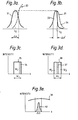
- FIGS. 3a and 3b illustrate the basis for the technique.
- An illuminating source provides a narrow-band spectrum 31 (Figure 3a) of nominal band width A), and mean wavelentgh ⁇ o Superimposed on this spectral profile is the absorption profile 32 of a gas to be detected.
- the spectral profile is shown overlapping the edge of the absorption spectral profile such that the absorption is wavelength dependent in the range ⁇ .
- the profile 31 will be representative of that received by a remote detector as shown in Figure 3b.
- the effective temporal coherence is increased.
- the presence of scattered radiation at the appropriate nominal mean wavelength X. equal to the transmitted wavelength but with increased temporal coherence, is an indication that the target gas is present at the remote site.
- Figures 3c and 3d illustrate the dependence of the change of temporal coherence on the overlap of the illumination and absorption profiles.
- the illumination and absorption spectra have sharp cut-offs and are rectangular in shape.
- Figure 3c corresponds to Figures 3a and 3b, the change in coherence being brought about by the illuminating spectrum 35 being reduced in width from W 1 to W 2 by the absorption profile 36.
- Figures 3a - 3d illustrate narrow band illuminating sources and by contrast figure 3e illustrates how a broad-band source such as the sun may be used.
- the sun's spectrum 39 is band-pass limited to a narrow band which coincides with a target gas absorption profile 40 - by providing a suitable filter at the receiver input.
- Figure 3e shows that broad band illumination, for example the solar spectrum 39, can be band-pass limited by an input filter of bandwidth 4ih to achieve the same effects shown in Figures 3a to 3d by arranging the passband to coincide with the profile 40 of the target gas absorption spectrum.
- a receiver capable of detecting temporal coherence changes for remote sensing should be selectively sensitive to small changes in temporal coherence and also should be insensitive to amplitude and intensity changes.
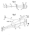
- Figure 4 shows a simple version of a high pass temporal coherence optical receiver which may be used, according to the present invention, in the apparatus for remote detection of gases.
- Light 41 from a remote scene is transmitted via a lens 42 and a stop 43 to a Fresnel bi-prism beam splitter 44.
- One half-beam is delayed by a glass delay plate 45 and the combination of the two half-beams is measured by a detector 46.
- the glass delay plate 45 introduces an additional path length in the upper half-beam and thus interference fringes will be observed by the detector 46 if the path difference is smaller than the coherence length of the light 41.
- the detector is made selectively sensitive to the interference fringes of the appropriate wavelength by the modulating reticle 47 and the filter 48. The reticle is oscillated back and forth while the detector searches for a synchronous signal.
- Sources such the Xenon lamp, with its array of narrow spectral features, can have their broad-band disadvantages offset to a great extent by the processing power of the temporal coherence detection system.
- a spectrum scanning scheme may be employed by the use of an electronically tunable optical filter as are now becoming available.
- the narrow-band illuminating beam can be spectrally scanned across the absorption spectrum to yield a frequency-modulated signal, proportional to the temporal coherence variations caused by the convolution of the two spectra.
- this scheme would be insensitive to amplitude variations as might be caused by for example: changes in transmitted power; variations in atmospheric turbulence and scatter; and changes in concentration of the target gas with position or air movement.
- a periodic modulation at a separately arranged frequency can also be induced by means of a vibrating scanning prism or mirror so that the contours of the extent of the target can be mapped.
- a receiver 51 such as the one shown in Figure 4, is colocated with an illuminating source 52 such as a laser.
- the receiver 51 can collect illumination scattered from the gas itself (indicated by 53) or scattered (54) from some remote surface 55 such as high ground or the side of a building etc.
- a retro-reflector 56 to enhance the illumination (57) received by the detector system.
- the illumination 54, 57 reflected back towards the receiver from behind the target gas has made a double pass through the target gas and so provides an advantageous enhancement of the temporal coherence.
- the illuminating radiation may alternatively be received by a remote receiver 58 after direct-line transmission through the target gas or by a remote receiver 59 responsive to scattered light 60.
- the receiver 51 may receive broad-band solar radiation 50' after transmission through the target gas.
- detector system depends, among other factors, upon the absorption profile of the particular target gas and the spectrum and power of the source of illumination.
- the power incident on the scattering surface is approximately: Wexp (- Sa.R). exp (- Sg.t)
- the scattering surface has a reflectance value of r and is Lambertian, then the reflected power per unit solid angle is:
- the power reaching the receiver is approximately given by:
- the ability of the high pass temporal coherence receiver ( Figure 4) to eliminate background clutter is illustrated by the response curves in Figure 6 obtained by scanning a field of view which includes a remote laser source.
- the upper trace shows the variation of response 61 against bearing measured by the Figure 4 arrangement, but without the Fresnel biprism 44 and modulating reticle 47.
- the laser radiation 62 is indistinguishable from the background clutter 63 because the receiver responds only to intensity variations.
- the lower trace shows the effect of introducing the reticle 47 and fresnel biprism 44 with a thin glass plate delay 45 attached. Even a thin delay plate, discriminating against relatively short temporal coherence radiation, is found to reduce the background clutter (64) substantially and make the laser radiation readily detectable.
- the thickness of the delay plate When used in the remote gas sensor the thickness of the delay plate must then be increased until the laser light from the remote gas detector is just extinguished. Any increase in the temporal coherence of the laser radiation received after interaction with the target gas will then lead to interference fringes in the plane of the reticle 47 and the generation of a modulated signal at the output of the detector 46.
- a phase modulator 83 comprising a glass delay plate which is tilted up and down cyclically produces periodic variations in intensity of any fringe patterns present at the detectors 81 and 82.
- the temporal coherence band pass is determined by varying the offset of the mirror 76 and the thickness of the glass delay plate 78.
- the remote-sensing technique can be optimised.
- a- turnable laser illuminator 52 may be frequency scanned.
- the centre frequency of a turnable narrow bandpass filter 83 at the input to the receiver may be channel.
- the method of the invention is also applicable when the area of interest is illuminated by sun's radiation, or when the area is illuminated by broad-band artificial sources such as arc lights, tungsten lamps, pyrotechnics, flares etc.
- a band-pass filter at the receiver input would be used to transmit an appropriate narrow spectral band unaffected by other sharp absorption spectra.
Abstract
Description
- The invention relates to the detection of gases and vapours or aerosols by remote or semi-remote sensing and in particular to the measurement of changes in phase and amplitude occurring at the site of interaction between illuminating energy and the remote gas, vapour or aerosol.
- Hereinafter the term gas is to be understood to include vapour or aerosol.
- There are many requirements for the detection of gases by remote sensing. For example, the monitoring of pollution from ground stations by air-borne sensors and by satellites. The monitoring of some forms of pollution has been shown to be feasible from orbiting space craft, for example particulate pollution and smoke plumes have been observed.
- Most of the techniques employed rely upon solar illumination for the remote sensing of gaseous pollutants and this is achieved by the identification of intensity changes in the spectrum characteristics of the reflected sunlight. Particularly severe problems have been encountered when using detection systems measuring in the ultraviolet (UV) since the solar energy at UV wavelengths is strongly absorbed by the ozonosphere, as for example in detecting pollution by sulphur dioxide. In the visible spectrum it has proved less difficult to design systems to detect for example oxides of nitrogen and halogens, while detection often becomes even easier in the infra-red region of the spectrum.
- Before any particular remote sensing techniques can be chosen a fairly comprehensive understanding of the physics of the atmosphere and the spectral characteristics of the solar illumination at particular altitudes must be known. The sun provides a powerful wide-band source of illumination which is particularly convenient to use, however a limitation of daylight detection may not always be acceptable. Because of the effects of scattering and atmospheric absorption only a very weak background illumination is available at the earth's surface in the UV region of the spectrum. At wavelengths longer than the rear infra-red (at 3-5 pm) the thermal emissions from the earth's surface (taken as a 300k blackbody) are greater than the solar reflected energy, and the C02 absorption beyond the 12-14 micron waveband sets an upper limit to the practical use of the infra-red (IR) window.
- The most widely used technique for remote detection is some form of correlation spectroscopy where a set of absorption bands is detected by one of the many basic types of spectrometer. The intensity profile of the dispersed spectrum is then modulated by a matching correlation mask, generally having alternate slits and bars, which is made to scan across the appropriate part of the optical spectrum. When the anticipated absorption spectrum is present in the received optical signal, a modulated signal of specific frequency content will appear at the output of a detector arranged behind the mask. This technique relies upon the detection of amplitude variation of the received spectrum, ie the change in absorption is detected by a change in signal amplitude (or intensity) against a background whose amplitude profile is a very complicated structure.
- In the conventional amplitute sensitive system, by increasing the number of matching slits and bars in the correlation mask to a greater number of features on the absorption profile of the gas to be detected, a greater degree of certainty-of-match can be obtained. However, as more spatial features are incorporated into the mask, more spatial harmonics are present with the consequence that other absorption spectra and irregularities in the background spectra may trigger a response.
- The object of the present invention is to provide a sensor and method for remote detection of gases which is capable of high sensitivity and accuracy.
- The invention comprises in one form a method for remote detection of a gas, vapour or aerosol comprising measurement of the change of temporal coherence of radiation illuminating the gas, vapour or aerosol due to absorption of radiation thereby.
- The temporal coherence of radiation of wavelengthxis inversely proportional to the spectral line widthSX. The spectral bandwidth of the scattered energy after passage through the target gas becomes narrower when the bandwidth overlaps an absorption feature in the gas absorption spectrum and thus the effective temporal coherence of the radiation is increased. Then the greater the narrowing of the illuminating spectrum the greater the change in temporal coherence (or coherence length) and the better the instrumentation can sense the presence of the gas etc. To the extent that the spectrum of the illuminating radiation can be controlled then the target gas's absorption line may be altered in position relative to the illuminating spectrum. The optimum positions can be stated as occurring when the change of Fourier Transform of the illuminating spectrum due to the presence of the target gas is maximised. In a preferred active form of the method, radiation is transmitted and after reflection by the gas, vapour or aerosol is detected by a receiver co-located with the radiation transmitter.
- Advantageously the receiver maybe arranged to discriminate against the transmitted radiation, responding only to radiation of longer temporal coherence than the transmitted radiation. In order to minimise false signals arising from any source of radiation of appropriately long temporal coherence (other than that returned from the target gas) which may be in the field of view the receiver may be arranged to respond only to increases in temporal coherence within a specified band-width. In an alternative semi-active arrangement use may be made of another illuminating souce such as sunlight or other radiation not purposefully arranged as a transmitter. A broadband source like the sun can be appropriately band-limited at the receiver toitnit ate a narrow-band active source. In a final passive alternative the invention may be used to detect a target gas etc. which is self-illuminating. In the active, semi-active or passive arrangements provision may be made to spectrally scan the changes in temporal coherence or Fourier Transform.
- The invention also provides apparatus for remote sensing of a gas, vapour or aerosol comprisingin one form: a transmitter capable of emitting radiation having a spectral line or band which at least partly overlaps a feature in the absorption spectrum of the gas, vapour or aerosol; radiation collecting means for receiving radiation from a predetermined field of view; and a detector responsive to changes in the temporal coherence of the transmitted radiation caused by interaction of the radiation with the gas, vapour or aerosol. Perferably the transmitter is a laser which may be tuned or the laser selected such that the transmitted radiation includes a spectral line or band in a wavelength range over which the target gas, vapour or aerosol has a changing absorption profile. In a second form suitable for semi-active or passive detection the transmitter may be replaced by a narrow-band transmission filter having a band-pass which at least partly overlaps a feature in the absorptionjtectrum of the gas, vapour or aerosol.
- The receiver may include a high pass temporal coherence filter which is insensitive to the transmitted or illuminating radiation. Advantageously the temporal coherence filter includes an interferometer wherein received radiation is split into two beams and then recombined, one of the beams having a longer path length than the other. The interferometer can conveniently include a Fresnel biprism, and a glass delay plate may be placed in one of the beams. An amplitude modulating reticle may be placed in the path of the recombined beams and cyclically moved so as to sensitise the detector to interference fringes.
- In an alternative arrangement the receiver may include a band pass temporal coherence filter with the lower band pass limit set above the temporal coherence of the transmitted or band-pass limited illuminating radiation. Conveniently the band pass tempor al coherence filter may include a Michelson interferometer wherein the received radiation is split into two beams and then recombined with the path length of the beams being different, an optical delay being placed in a portion of one of the beams so as to increase the path length of the portion of the beam and detector means selectively responsive to interference fringes produced on recombination of one portion only of the one beam with the other beam. In one arrangement there may be provided a prism to separate the recombined beams to respective detectors for the selective response.
- In the active form of the detector a turnable laser may be used together with means to scan the transmitted frequency such that the wavelength dependance of the change in Fourier Transform or temporal coherence can be determined.
- In the semi-active or passive forms of the detector a tu nable band-pass filter may be used to vary the pass-band of the received illumination, such that the wavelength dpendence of the change in Fourier Transform or temporal coherence can again be determined.
- The invention will now be described by way of example only with reference to the accompanying Drawings of which:-
- Figure 1 illustrates a prior art correlation spectrometer;
- Figure 2 shows the absorption spectrum of a target gas (sulphur dioxide) and the matching correlation mask used for its detection in the Figure 1 arrangement;
- Figures 3a and 3b respectively show a typical spectrum of an illuminating narrow band-width source with a superimposed target gas absorption spectrum, and the spectrum of reflected and scattered radiation from the gas;
- Figures 3c and 3d illustrate the dependence of the Fourier Transform change on the over lap of illuminating spectrum and target gas absorption spectrum;
- Figure 3e illustrates the use of a band-pass filter to simulate the effects of Figures 3a - 3d with broad-band illumination.
- Figure 4 shows a simple high-pass temporal coherence receiver employed by the invention;
- Figure 5 shows schematically a number of remote gas detection arrangements;
- Figure 6 shows the effect of temporal coherence filtering in an optical detection system; and
- Figures 7a and 7b show a band pass temporal coherence sensor in plan and elevation.
- Figures 1 and 2 illustrate the use of a conventional correlation spectometer applied to the remote detection of gases. Light 1 from a target area is collected by an
input lens system 2. The light is focussed by lens 3 on to anentrance slit 4 and then passes through a modulatedrefractor plate 5 to aconcave mirror 6. Light from theconcave mirror 6 is focussed on to a diffraction grating 7 and then passes through acorrelation mask 8 to a photo-detector 9. Figure 2 shows the absorption spectrum for sulphur dioxide in the wavelength region near 300mm and this shows several sbsorption bands. The bands in thewavelength range 10 are matched to the alternating opaque and transparent strips on thecorrelation mask 8. As shown, 5 when thecorrelation mask 8 is placed in register with thespectral range 10 the transmitted light will be a minimum. The action of therefractor plate 5, which is oscillated by an electronically maintainedtuning fork 11, together with the lens 3 andentrance slit 4 arrangement, is to scan the spectral profile of the received light back-and-forth across themask 8. When, as in this example, the received light has passed through a region of sulphur dioxide and absorption bands characteristic of sulphur dioxide are present in its spectrum then a modulated signal of specific frequency content will appear at the output of thedetector 9. In this arrangement, as in other prior art arrangements, a change in absorption is detected by a change in signal amplitude (or intensity) against a background whose amplitude profile may be very complicated. - By increasing the number of matching slits and bars in the
correlation mask 8 to a greater number of features on the absorption profile of the gas to be detected, a greater degree of certainty-of-match can be obtained. However, as more spatial features are incorporated into the mask, more spatial harmonics are present, with the consequence that other absorption spectra and irregularities in the background spectra may trigger a response and lead to a spurious signal. - The conventional correlation technique depends to a great extent on using compatible regions of the spectrum for both the target and the background. Firstly, adequate illumination must exist at a region which is suitable for a highly discriminating profile, and secondly the region must be reasonably clear from overlapping spectra having similar spatial frequencies. Solar illumination is advantageous because it is both broad-band and intense. Lasers can provide a versatile source of illumination, however they have very narrow band-widths and therefore the exploration of characteristics with wide spectral profiles, as in the correlation spectrometer described above, would be be extremely difficult and in most contexts impractical.
- The present invention depends upon the changes in temporal coherence or the Fourier Transform which take place on interaction between the illuminating energy and the target gas in addition to other filtering processes. Figures 3a and 3b illustrate the basis for the technique. An illuminating source provides a narrow-band spectrum 31 (Figure 3a) of nominal band width A), and mean wavelentgh λo Superimposed on this spectral profile is the
absorption profile 32 of a gas to be detected. The spectral profile is shown overlapping the edge of the absorption spectral profile such that the absorption is wavelength dependent in the range Δλ. In the absence of the gas theprofile 31 will be representative of that received by a remote detector as shown in Figure 3b. With gas present, however, radiation transmitted through the gas (or reflected and scattered after passage through the gas) will have aspectral profile 33 of reduced band width Δλ' at about the same mean wavelength λo, the shadedarea 34 corresponding to the change in spectral profile. - The coherence length (Lc) of radiation of spectral width Ah is given by

- where: c = velocity of light;
- λo = mean wavelength of the radiation; and
- δλ = spectral width in wavelength units
- Hence, as the spectral bandwidth of the scattered energy after passage through the target gas becomes narrower, then the effective temporal coherence is increased. Thus the presence of scattered radiation at the appropriate nominal mean wavelength X. , equal to the transmitted wavelength but with increased temporal coherence, is an indication that the target gas is present at the remote site.
- Figures 3c and 3d illustrate the dependence of the change of temporal coherence on the overlap of the illumination and absorption profiles. In both Figures the illumination and absorption spectra have sharp cut-offs and are rectangular in shape. Figure 3c corresponds to Figures 3a and 3b, the change in coherence being brought about by the illuminating
spectrum 35 being reduced in width from W1 to W2 by theabsorption profile 36. In figure 3d theabsorption profile 37 is in the centre of the illuminatingspectrum 38. This leaves two lines of width W3 (=W2/2) with higher coherence. - Figures 3a - 3d illustrate narrow band illuminating sources and by contrast figure 3e illustrates how a broad-band source such as the sun may be used. The sun's
spectrum 39 is band-pass limited to a narrow band which coincides with a target gas absorption profile 40 - by providing a suitable filter at the receiver input. - Figure 3e shows that broad band illumination, for example the
solar spectrum 39, can be band-pass limited by an input filter of bandwidth 4ih to achieve the same effects shown in Figures 3a to 3d by arranging the passband to coincide with theprofile 40 of the target gas absorption spectrum. - A receiver capable of detecting temporal coherence changes for remote sensing should be selectively sensitive to small changes in temporal coherence and also should be insensitive to amplitude and intensity changes. Figure 4 shows a simple version of a high pass temporal coherence optical receiver which may be used, according to the present invention, in the apparatus for remote detection of gases.
Light 41 from a remote scene is transmitted via alens 42 and astop 43 to a Fresnelbi-prism beam splitter 44. One half-beam is delayed by aglass delay plate 45 and the combination of the two half-beams is measured by adetector 46. Theglass delay plate 45 introduces an additional path length in the upper half-beam and thus interference fringes will be observed by thedetector 46 if the path difference is smaller than the coherence length of the light 41. By approximate selection of the delay introduced by thedelay plate 45 the receiver can be made to produce interference fringes only when the target gas is in the field of view. The detector is made selectively sensitive to the interference fringes of the appropriate wavelength by the modulatingreticle 47 and thefilter 48. The reticle is oscillated back and forth while the detector searches for a synchronous signal. - For the simple arrangement described above it is necessary to illuminate the volume of air to be searched by a source which can be tuned, or be arranged, to be adjacent to an appropriate absorption feature of the target gas or aerosol etc as shown in Figure 3a. In many cases this can be achieved by current laser technology, and as more widely tunable lasers become available in the future, the difficulties of matching the illumination to the target's charcte- ristics can be expected to decrease. However, due to high sensitivity of the temporal coherence detection scheme, many more lasers are almost certaintly suitable candidates as illuminators than would otherwise be available for the normal amplitude-sensitive electro-optical schemes. Due to the very narrow beam divergence and the near monchromatic nature of laser radiation, the power-spectral density at the target is high. Sources such the Xenon lamp, with its array of narrow spectral features, can have their broad-band disadvantages offset to a great extent by the processing power of the temporal coherence detection system.
- A spectrum scanning scheme may be employed by the use of an electronically tunable optical filter as are now becoming available. In this mode the narrow-band illuminating beam can be spectrally scanned across the absorption spectrum to yield a frequency-modulated signal, proportional to the temporal coherence variations caused by the convolution of the two spectra. As with the simple temporal coherence system, this scheme would be insensitive to amplitude variations as might be caused by for example: changes in transmitted power; variations in atmospheric turbulence and scatter; and changes in concentration of the target gas with position or air movement.
- A periodic modulation at a separately arranged frequency can also be induced by means of a vibrating scanning prism or mirror so that the contours of the extent of the target can be mapped.
- There are a number of distinct physical arrangements which can be used for remote sampling of a
target gas 50. These are shown schematically in Figure 5. A receiver 51, such as the one shown in Figure 4, is colocated with an illuminatingsource 52 such as a laser. The receiver 51 can collect illumination scattered from the gas itself (indicated by 53) or scattered (54) from someremote surface 55 such as high ground or the side of a building etc. In some applications it may also be possible to employ a retro-reflector 56 to enhance the illumination (57) received by the detector system. Theillumination remote receiver 58 after direct-line transmission through the target gas or by aremote receiver 59 responsive toscattered light 60. - In addition the receiver 51 may receive broad-band solar radiation 50' after transmission through the target gas.
- The choice of detector system depends, among other factors, upon the absorption profile of the particular target gas and the spectrum and power of the source of illumination.
- The power incident on the scattering surface is approximately:
Wexp (- Sa.R). exp (- Sg.t) - where: W is the illuminating power a collimated beam;
- Sa is the extinction coefficient of the normal air path;
- Sg is the extinction coefficient of the target gas cloud;
- R is the range; and
- t is the thickness of the cloud.
- Assuming that the scattering surface has a reflectance value of r and is Lambertian, then the reflected power per unit solid angle is:

- The power reaching the receiver is approximately given by:

- Where the proportion of the reflected energy which passes back through the gas and enters the receiver is Wr/Wtn.
- The above expression gives only an approximate guide since it may be difficult to estimate values for δa and 8g, and the exact line profiles and their relative positions are important.
- The ability of the high pass temporal coherence receiver (Figure 4) to eliminate background clutter is illustrated by the response curves in Figure 6 obtained by scanning a field of view which includes a remote laser source. The upper trace shows the variation of
response 61 against bearing measured by the Figure 4 arrangement, but without theFresnel biprism 44 and modulatingreticle 47. Thelaser radiation 62 is indistinguishable from thebackground clutter 63 because the receiver responds only to intensity variations. The lower trace shows the effect of introducing thereticle 47 andfresnel biprism 44 with a thinglass plate delay 45 attached. Even a thin delay plate, discriminating against relatively short temporal coherence radiation, is found to reduce the background clutter (64) substantially and make the laser radiation readily detectable. When used in the remote gas sensor the thickness of the delay plate must then be increased until the laser light from the remote gas detector is just extinguished. Any increase in the temporal coherence of the laser radiation received after interaction with the target gas will then lead to interference fringes in the plane of thereticle 47 and the generation of a modulated signal at the output of thedetector 46. - Where there is a light source in the field of view of narrower band-width than the illuminating source then the simple high pass from the
beam splitter 72 compared withmirror 75. By arranging a near balance between the two delays introduced by the mirror offset and glass delay plate, very fine differences in temporal band-pass setting can be achieved. As can be seen particularly in Figure 7b the positioning of theglass delay plate 78 leads to abeam 79 in which the upper half requires a lower temporal coherence in theincident light 71 for the presence of interference than the lower half. The two half beams are separated by theprism 80 and detected byseparate detectors phase modulator 83 comprising a glass delay plate which is tilted up and down cyclically produces periodic variations in intensity of any fringe patterns present at thedetectors mirror 76 and the thickness of theglass delay plate 78. - By providing simple spectral band-limiting and electronic correlation the remote-sensing technique can be optimised.
- The juxta position of the target gas's absorption line and illuminating spectrum might not be ideal in practice. Each case would need to be separately judged because the spectra would be different and technical limitations might prevent achievement of the most efficient illuminator. This problem may be eased by measuring (FT)/δλ : the wavelength dependence on the Fourier Transform (or the temporal coherence). In the active detector, a-
turnable laser illuminator 52 may be frequency scanned. In a semi-active or passive detector making use of other sources illuminating a target gas or a self-illuminating target gas, the centre frequency of a turnablenarrow bandpass filter 83 at the input to the receiver may be channel. To scanning agent and would automatically reveal the maximum of the δ(FT)/δλ positions without the need for calculation and/or trial and error. In addition these systems would be more sensitive to gases whose absorption profiles were partially obscurred by absorption in the intervening path (eg. atmospheric path). - The method of the invention is also applicable when the area of interest is iluminated by sun's radiation, or when the area is illuminated by broad-band artificial sources such as arc lights, tungsten lamps, pyrotechnics, flares etc. A band-pass filter at the receiver input would be used to transmit an appropriate narrow spectral band unaffected by other sharp absorption spectra. Other modifications of the method and apparatus will be readily apparent to those skilled in the art, all falling within the scope of the invention described herein.
Claims (12)
Applications Claiming Priority (2)
| Application Number | Priority Date | Filing Date | Title |
|---|---|---|---|
| GB8406690 | 1984-03-14 | ||
| GB848406690A GB8406690D0 (en) | 1984-03-14 | 1984-03-14 | Remote sensing of gases &c |
Publications (3)
| Publication Number | Publication Date |
|---|---|
| EP0155142A2 true EP0155142A2 (en) | 1985-09-18 |
| EP0155142A3 EP0155142A3 (en) | 1986-06-25 |
| EP0155142B1 EP0155142B1 (en) | 1989-05-03 |
Family
ID=10558087
Family Applications (1)
| Application Number | Title | Priority Date | Filing Date |
|---|---|---|---|
| EP85301544A Expired EP0155142B1 (en) | 1984-03-14 | 1985-03-06 | Apparatus and method for remote sensing of gases, vapours or aerosols |
Country Status (6)
| Country | Link |
|---|---|
| US (1) | US4676642A (en) |
| EP (1) | EP0155142B1 (en) |
| JP (1) | JPS60210741A (en) |
| CA (1) | CA1237177A (en) |
| DE (1) | DE3569981D1 (en) |
| GB (1) | GB8406690D0 (en) |
Cited By (2)
| Publication number | Priority date | Publication date | Assignee | Title |
|---|---|---|---|---|
| US4692026A (en) * | 1984-09-25 | 1987-09-08 | Hoechst Aktiengesellschaft | Process and apparatus for continuous determination of the states of anisotropy of optically active materials |
| WO1993001477A1 (en) * | 1991-07-12 | 1993-01-21 | The Secretary Of State For Defence In Her Britannic Majesty's Government Of The United Kingdom Of Great Britain And Northern Ireland | Optical signal processing |
Families Citing this family (33)
| Publication number | Priority date | Publication date | Assignee | Title |
|---|---|---|---|---|
| US5327219A (en) * | 1992-05-15 | 1994-07-05 | The United States Of America As Represented By The Administrator Of The National Aeronautics And Space Administration | Method and apparatus for removing unwanted reflections from an interferometer |
| US5373160A (en) * | 1993-05-04 | 1994-12-13 | Westinghouse Electric Corporation | Remote hazardous air pullutants monitor |
| GB2297656A (en) * | 1995-02-01 | 1996-08-07 | Northern Telecom Ltd | Optical filtering |
| US5905571A (en) * | 1995-08-30 | 1999-05-18 | Sandia Corporation | Optical apparatus for forming correlation spectrometers and optical processors |
| US5770156A (en) * | 1996-06-04 | 1998-06-23 | In Usa, Inc. | Gas detection and measurement system |
| GB2314617B (en) * | 1996-06-24 | 2000-08-23 | Graviner Ltd Kidde | High sensitivity gas detection |
| WO1998017991A1 (en) * | 1996-10-18 | 1998-04-30 | In Usa, Inc. | Multi-wavelength based ozone measurement method and apparatus |
| DE19856400B4 (en) * | 1998-12-07 | 2009-04-09 | Steinbichler Optotechnik Gmbh | Method and device for the direct phase measurement of radiation |
| US6568597B2 (en) | 2000-11-29 | 2003-05-27 | Symbol Technologies, Inc. | Scanning system with adjustable optical characteristics |
| US6885965B2 (en) * | 2002-05-22 | 2005-04-26 | First Responder Systems Technologies, Llc | Processing system for remote chemical identification |
| US20060237665A1 (en) * | 2003-03-10 | 2006-10-26 | Barney William S | Bioaerosol discrimination |
| US7060992B1 (en) | 2003-03-10 | 2006-06-13 | Tiax Llc | System and method for bioaerosol discrimination by time-resolved fluorescence |
| CA2458123C (en) * | 2003-03-13 | 2012-05-15 | Synodon Inc. | Remote sensing of gas leaks |
| EP1620004A2 (en) * | 2003-04-15 | 2006-02-01 | Optiscan Biomedical Corporation | Dual measurement analyte detection system |
| DE602004030884D1 (en) * | 2004-02-16 | 2011-02-17 | Synodon Inc | Remote sensing of gas leaks using gas filter correlation radiometry |
| CN1329715C (en) * | 2004-11-16 | 2007-08-01 | 中国科学院安徽光学精密机械研究所 | Probe of airborne multi wave section bidirection atmosphere radiation detecting instrument |
| US7355705B1 (en) * | 2005-06-23 | 2008-04-08 | Itt Manufacturing Enterprises, Inc. | Using a fixed-frequency oscillation in a dispersive spectrometer to measure scene inhomogeneity |
| US7791719B1 (en) | 2007-01-12 | 2010-09-07 | Itt Manufacturing Enterprises, Inc. | Using a fixed-frequency oscillation to detect and measure scene inhomogeneity |
| IL190756A0 (en) * | 2008-04-09 | 2009-08-03 | Rafael Advanced Defense Sys | Gas detection, identification and concentration estimation based on spectral spatial misregistration |
| US20120101747A1 (en) * | 2010-10-25 | 2012-04-26 | University Of Louisville Research Foundation, Inc. | Detection and imaging of turbulence in a fluid |
| CN104297117A (en) * | 2014-10-23 | 2015-01-21 | 浙江省环境保护科学设计研究院 | Scenic area road traffic pollution early-warning device based on remote sensing technique and scenic area road traffic pollution early-warning method based on remote sensing technique |
| US10349491B2 (en) | 2015-01-19 | 2019-07-09 | Tetra Tech, Inc. | Light emission power control apparatus and method |
| CA2892952C (en) | 2015-01-19 | 2019-10-15 | Tetra Tech, Inc. | Protective shroud |
| CA2893007C (en) | 2015-01-19 | 2020-04-28 | Tetra Tech, Inc. | Sensor synchronization apparatus and method |
| US9618335B2 (en) | 2015-01-19 | 2017-04-11 | Tetra Tech, Inc. | Light emission power control apparatus and method |
| US10362293B2 (en) | 2015-02-20 | 2019-07-23 | Tetra Tech, Inc. | 3D track assessment system and method |
| WO2017030652A1 (en) | 2015-08-20 | 2017-02-23 | Massachusetts Institute Of Technology | Sensing targets using photothermal speckle detection |
| US10730538B2 (en) | 2018-06-01 | 2020-08-04 | Tetra Tech, Inc. | Apparatus and method for calculating plate cut and rail seat abrasion based on measurements only of rail head elevation and crosstie surface elevation |
| US10625760B2 (en) | 2018-06-01 | 2020-04-21 | Tetra Tech, Inc. | Apparatus and method for calculating wooden crosstie plate cut measurements and rail seat abrasion measurements based on rail head height |
| US11377130B2 (en) | 2018-06-01 | 2022-07-05 | Tetra Tech, Inc. | Autonomous track assessment system |
| US10807623B2 (en) | 2018-06-01 | 2020-10-20 | Tetra Tech, Inc. | Apparatus and method for gathering data from sensors oriented at an oblique angle relative to a railway track |
| US10908291B2 (en) | 2019-05-16 | 2021-02-02 | Tetra Tech, Inc. | System and method for generating and interpreting point clouds of a rail corridor along a survey path |
| CN114544452B (en) * | 2022-04-25 | 2022-07-26 | 自然资源部第二海洋研究所 | Multi-angle polarized water color remote sensor satellite atmosphere correction method |
Citations (2)
| Publication number | Priority date | Publication date | Assignee | Title |
|---|---|---|---|---|
| GB957737A (en) * | 1961-06-09 | 1964-05-13 | Ass Elect Ind | Improvements relating to spectrometers |
| US4170416A (en) * | 1977-01-17 | 1979-10-09 | The Perkin-Elmer Corporation | Apparatus for analyzing coherent radiation |
Family Cites Families (6)
| Publication number | Priority date | Publication date | Assignee | Title |
|---|---|---|---|---|
| US3563663A (en) * | 1966-07-13 | 1971-02-16 | Barringer Research Ltd | Analysis of spectra by correlation of interference patterns |
| GB1195840A (en) * | 1967-01-10 | 1970-06-24 | Barringer Research Ltd | Scanning Interferometer Using Wedge for Producing Fringes |
| JPS5144832B2 (en) * | 1972-03-31 | 1976-12-01 | ||
| US3914055A (en) * | 1974-05-23 | 1975-10-21 | Lansing Research Corp | Instrument for high resolution spectral analysis with large optical throughput |
| US4035643A (en) * | 1974-06-11 | 1977-07-12 | Allied Chemical Corporation | Infrared gas analysis |
| JPS5198072A (en) * | 1975-02-25 | 1976-08-28 | Heterodainhoshiki reeza reedasochi |
-
1984
- 1984-03-14 GB GB848406690A patent/GB8406690D0/en active Pending
-
1985
- 1985-03-06 DE DE8585301544T patent/DE3569981D1/en not_active Expired
- 1985-03-06 EP EP85301544A patent/EP0155142B1/en not_active Expired
- 1985-03-06 US US06/708,790 patent/US4676642A/en not_active Expired - Fee Related
- 1985-03-13 JP JP60050242A patent/JPS60210741A/en active Pending
- 1985-03-13 CA CA000476359A patent/CA1237177A/en not_active Expired
Patent Citations (2)
| Publication number | Priority date | Publication date | Assignee | Title |
|---|---|---|---|---|
| GB957737A (en) * | 1961-06-09 | 1964-05-13 | Ass Elect Ind | Improvements relating to spectrometers |
| US4170416A (en) * | 1977-01-17 | 1979-10-09 | The Perkin-Elmer Corporation | Apparatus for analyzing coherent radiation |
Non-Patent Citations (1)
| Title |
|---|
| JOURNAL OF OPTICS, vol. 9, no. 5, 1978, pages 281-290, Paris, FR; G. FORTUNATO: "Application de la corrélation interférentielle de spectres a la détection de polluants atmosphériques" * |
Cited By (4)
| Publication number | Priority date | Publication date | Assignee | Title |
|---|---|---|---|---|
| US4692026A (en) * | 1984-09-25 | 1987-09-08 | Hoechst Aktiengesellschaft | Process and apparatus for continuous determination of the states of anisotropy of optically active materials |
| WO1993001477A1 (en) * | 1991-07-12 | 1993-01-21 | The Secretary Of State For Defence In Her Britannic Majesty's Government Of The United Kingdom Of Great Britain And Northern Ireland | Optical signal processing |
| GB2272765A (en) * | 1991-07-12 | 1994-05-25 | Secr Defence | Optical signal processing |
| GB2272765B (en) * | 1991-07-12 | 1995-04-05 | Secr Defence | Optical signal processing |
Also Published As
| Publication number | Publication date |
|---|---|
| CA1237177A (en) | 1988-05-24 |
| GB8406690D0 (en) | 1984-04-18 |
| JPS60210741A (en) | 1985-10-23 |
| DE3569981D1 (en) | 1989-06-08 |
| EP0155142A3 (en) | 1986-06-25 |
| US4676642A (en) | 1987-06-30 |
| EP0155142B1 (en) | 1989-05-03 |
Similar Documents
| Publication | Publication Date | Title |
|---|---|---|
| US4676642A (en) | Apparatus and method for remote sensing of gases, vapors or aerosols | |
| US5339155A (en) | Optical wavelength modulated long-path gas monitoring apparatus | |
| US5451787A (en) | Hazardous air pollutants monitor | |
| US8330957B2 (en) | Device and method for quantification of gases in plumes by remote sensing | |
| US6822236B1 (en) | Method of optimizing a response of a gas correlation radiometer to a trace amount of a target gas | |
| US5373160A (en) | Remote hazardous air pullutants monitor | |
| US5026992A (en) | Spectral ratioing technique for NDIR gas analysis using a differential temperature source | |
| US7397568B2 (en) | Coherent differential absorption lidar (dial) | |
| US5076699A (en) | Method and apparatus for remotely and portably measuring a gas of interest | |
| CA2365866C (en) | Passive remote sensor of chemicals | |
| US3723007A (en) | Remote quantitative analysis of materials | |
| US20110133089A1 (en) | Remote sensing of gas leaks | |
| US3517190A (en) | Method of remotely monitoring stack effluent | |
| WO1990010203A1 (en) | Air turbulence detection | |
| DK2588847T3 (en) | Device and method for the quantification of gases in the tabs by telemetering | |
| WO2018213212A1 (en) | Standoff trace chemical detection with active infrared spectroscopy | |
| US4383181A (en) | Method and apparatus for analyzing a gaseous mixture | |
| US8514378B2 (en) | Method of optical teledetection of compounds in a medium | |
| US11041754B2 (en) | Standoff trace chemical detection with active infrared spectroscopy | |
| CA2804006C (en) | Device and method for quantification of gases in plumes by remote sensing | |
| Davies et al. | Gaseous correlation spectrometric measurements | |
| US20230056282A1 (en) | Open path gas detector based on spectrometer | |
| Vaughan, Chair | Remote sensing terminology | |
| McKay et al. | Direct detection wind speed Doppler lidar systems | |
| Russwurm et al. | Glossary of Terms for Optical Remote Sensing |
Legal Events
| Date | Code | Title | Description |
|---|---|---|---|
| PUAI | Public reference made under article 153(3) epc to a published international application that has entered the european phase |
Free format text: ORIGINAL CODE: 0009012 |
|
| AK | Designated contracting states |
Designated state(s): DE FR GB NL |
|
| PUAL | Search report despatched |
Free format text: ORIGINAL CODE: 0009013 |
|
| AK | Designated contracting states |
Kind code of ref document: A3 Designated state(s): DE FR GB NL |
|
| 17P | Request for examination filed |
Effective date: 19861208 |
|
| 17Q | First examination report despatched |
Effective date: 19880801 |
|
| GRAA | (expected) grant |
Free format text: ORIGINAL CODE: 0009210 |
|
| AK | Designated contracting states |
Kind code of ref document: B1 Designated state(s): DE FR GB NL |
|
| REF | Corresponds to: |
Ref document number: 3569981 Country of ref document: DE Date of ref document: 19890608 |
|
| ET | Fr: translation filed | ||
| PLBI | Opposition filed |
Free format text: ORIGINAL CODE: 0009260 |
|
| 26 | Opposition filed |
Opponent name: SOCIETE NATIONALE ELF AQUITAINE Effective date: 19900202 |
|
| NLR1 | Nl: opposition has been filed with the epo |
Opponent name: SOCIETE NATIONALE ELF AQUITAINE |
|
| PLBM | Termination of opposition procedure: date of legal effect published |
Free format text: ORIGINAL CODE: 0009276 |
|
| STAA | Information on the status of an ep patent application or granted ep patent |
Free format text: STATUS: OPPOSITION PROCEDURE CLOSED |
|
| 27C | Opposition proceedings terminated |
Effective date: 19911003 |
|
| NLR2 | Nl: decision of opposition | ||
| PGFP | Annual fee paid to national office [announced via postgrant information from national office to epo] |
Ref country code: FR Payment date: 19950208 Year of fee payment: 11 |
|
| PGFP | Annual fee paid to national office [announced via postgrant information from national office to epo] |
Ref country code: GB Payment date: 19950216 Year of fee payment: 11 |
|
| PGFP | Annual fee paid to national office [announced via postgrant information from national office to epo] |
Ref country code: DE Payment date: 19950217 Year of fee payment: 11 |
|
| PGFP | Annual fee paid to national office [announced via postgrant information from national office to epo] |
Ref country code: NL Payment date: 19950331 Year of fee payment: 11 |
|
| PG25 | Lapsed in a contracting state [announced via postgrant information from national office to epo] |
Ref country code: GB Effective date: 19960306 |
|
| PG25 | Lapsed in a contracting state [announced via postgrant information from national office to epo] |
Ref country code: NL Effective date: 19961001 |
|
| GBPC | Gb: european patent ceased through non-payment of renewal fee |
Effective date: 19960306 |
|
| PG25 | Lapsed in a contracting state [announced via postgrant information from national office to epo] |
Ref country code: FR Effective date: 19961129 |
|
| NLV4 | Nl: lapsed or anulled due to non-payment of the annual fee |
Effective date: 19961001 |
|
| PG25 | Lapsed in a contracting state [announced via postgrant information from national office to epo] |
Ref country code: DE Effective date: 19961203 |
|
| REG | Reference to a national code |
Ref country code: FR Ref legal event code: ST |