EP0154891B1 - Interchangeable container transport system - Google Patents
Interchangeable container transport system Download PDFInfo
- Publication number
- EP0154891B1 EP0154891B1 EP85102167A EP85102167A EP0154891B1 EP 0154891 B1 EP0154891 B1 EP 0154891B1 EP 85102167 A EP85102167 A EP 85102167A EP 85102167 A EP85102167 A EP 85102167A EP 0154891 B1 EP0154891 B1 EP 0154891B1
- Authority
- EP
- European Patent Office
- Prior art keywords
- frame
- pick
- container
- vehicle
- longitudinal members
- Prior art date
- Legal status (The legal status is an assumption and is not a legal conclusion. Google has not performed a legal analysis and makes no representation as to the accuracy of the status listed.)
- Expired
Links
Images


Classifications
-
- B—PERFORMING OPERATIONS; TRANSPORTING
- B60—VEHICLES IN GENERAL
- B60P—VEHICLES ADAPTED FOR LOAD TRANSPORTATION OR TO TRANSPORT, TO CARRY, OR TO COMPRISE SPECIAL LOADS OR OBJECTS
- B60P1/00—Vehicles predominantly for transporting loads and modified to facilitate loading, consolidating the load, or unloading
- B60P1/64—Vehicles predominantly for transporting loads and modified to facilitate loading, consolidating the load, or unloading the load supporting or containing element being readily removable
- B60P1/6418—Vehicles predominantly for transporting loads and modified to facilitate loading, consolidating the load, or unloading the load supporting or containing element being readily removable the load-transporting element being a container or similar
- B60P1/6454—Vehicles predominantly for transporting loads and modified to facilitate loading, consolidating the load, or unloading the load supporting or containing element being readily removable the load-transporting element being a container or similar the load transporting element being shifted by means of an inclined ramp connected to the vehicle
Definitions
- Swap body transport systems consist of a vehicle and an interchangeable container, a device being provided on the vehicle to set the interchangeable container down at a desired location and to pick it up again after loading.
- the swap bodies are adapted to the respective use and can be designed as open and closed containers or just as a platform.
- One of these systems consists of a hydraulically extendable hook which grasps ropes or chains attached to eyelets or protrusions provided laterally at the top of the container.
- the size of the container is limited in both width and length.
- Another system includes a caster frame that can be pivoted at the rear end of the vehicle about an axis running transversely to the longitudinal axis of the vehicle and that can be pivoted out of a position lying on the loading area into an inclined position, the swap body being pivoted onto the caster frame by means of a pulling device via two casters attached to the vehicle can be drawn up after its pulling element has been connected to a receiving device on the swap body.
- the traction device consists of two rope drums driven by a hydraulic motor, which are mounted on the free end of the crawler frame and roll up two ropes after they have been connected to the swap body standing and loaded on the floor.
- the swap body is provided underneath its base plate with two longitudinal beams that run parallel to one another and angled upwards on at least one of the two swap body faces, the distance of which corresponds to the lateral distance between the two vehicle-side castors, and their length in the angled area in front of the face at least the vertical Distance of the rollers corresponds to the ground.
- a fastening hook is arranged below the container on the side surface of each side member, and a deflection roller is also arranged at the point of bending of the side members. This system also enables the use of relatively long containers.
- the overrun frame of the vehicle is adjusted to the inclined position of the container and the container is pulled onto the overrun frame by further winding up the steel cables.
- the inclined position of the container increases further, as a result of which the run-on frame has to be adapted to the changed inclined position several times. In this case, it is actually not the container that is pulled onto the overrun frame, but the vehicle further under the inclined container until it lies completely on the overrun frame and the overrun frame can be lowered again onto the loading area of the vehicle.
- the unloading process takes place accordingly, whereby the swap body automatically slides down from the swiveled up frame by its own gravity and the sliding speed of the container is determined by the length of the steel cable per unit of time.
- a disadvantage of the known system is that the swap body at its front end must be raised or lowered by the vertical distance of the rollers from the ground when it is placed on the rollers, so that the container is inevitably inclined by a large angle.
- the result of this angle of inclination is that an open container at the top can only be partially filled during the transport of bulk material, because otherwise the bulk material falls out over the rear wall of the container.
- the large angle of inclination of cargo of all types causes them to slide backwards, which shifts the center of gravity of the container.
- the invention is based on an interchangeable container transport system of the last-mentioned type, in which the container is pulled onto a pivotable caster frame via a pulling element.
- the invention has for its object to keep the angle of inclination when loading and unloading the container low in such a system and to make handling easier.
- the interchangeable container consists of a stable frame construction which serves as a supporting structure for the floor and walls, and which is extended downwards on the sides of the floor, the lateral distance of the Extensions are selected so that they overlap the vehicle tires when the swap body is swiveled downwards, that the receiving device on the swap body is arranged on the end face in the region of its central longitudinal plane and is designed as one element of a coupling, and that the other is connected to the tension element Coupling element is guided displaceably in the overrun frame in the direction of its longitudinal axis.
- the invention has the advantage that the container rests with its extensions on the ground and thus the bottom of the container is at a distance corresponding to the height of the extensions from the ground. Since the extensions overlap the vehicle tires on the side, the container only needs to be raised slightly during the charging process, namely by the distance between the container bottom and the rear end of the run-on frame. This measure considerably reduces the angle of inclination when loading the container, so that, on the one hand, better utilization of the container when loading with bulk material is possible and, on the other hand, the lateral tilting stability of the vehicle is increased.
- the raising of the container bottom when the container is on the ground also has the advantage that the receiving device for the tension element can be attached at such a height that the connection of the tension element and the receiving device can be designed as an automatically acting coupling, so that the vehicle only the container needs to be moved up and then the connection of the pulling device to the container is established automatically.
- the frame structure preferably contains at its corners two front posts and two rear posts, the front and rear posts being connected to one another on each side by two longitudinal spars, one of which is arranged at the level of the floor and the second below the floor and is connected to the first spar by connecting struts, and wherein the longitudinal spars are connected to one another by transverse spars.
- Such a frame construction has the advantage that the container walls do not have to make any contribution to the stability of the container, so that the container walls can optionally be attached by the user.
- This enables the container to be quickly and conveniently adapted to the desired application. For example, only one front wall and one rear wall can be installed, which enables easy lateral loading even for large-volume loads and the load is fixed on the base plate between the front and rear walls in the direction of travel. If, on the other hand, all four container walls are installed, the same container can hold bulk goods, for example, while if only the rear container wall is left out, loads that protrude beyond the container length can be transported without any problems.
- the container can be used as a platform.
- the receiving device is preferably attached in the middle to the front cross member and is designed as a catching device for a hook, the hook representing the vehicle-side coupling element and being seated on an arm which is pivotally mounted about a horizontal axis at the rear end of a sliding carriage which is in the longitudinal members of the caster is slidably guided, and wherein the end of the tension element is attached to the hook.
- An expedient embodiment provides that the carriage is of two-axis design, that the longitudinal members of the caster frame are angled downwards at their rear end, that the length of the angled end region is less than the center distance of the carriage, and that the arm is from a rest position, in which it rests on the carriage, can be swung out into an operating position in which the hook, when the carriage is arranged in the angled end region of the side members, lies at the level of the receiving device of an interchangeable container standing on the floor.
- This construction ensures that the Hook comes into the receiving device of the container when the vehicle is reset, so that it is then only necessary to switch on the pulling device.
- the tension element which is preferably made of a steel cable
- the arm swivels back into its rest position on the carriage. During this swiveling movement, the hook automatically engages in the receiving device.
- the pivoting movement of the arm causes the swap body to be lifted, the container depending on the arrangement of the lateral castors either with the lower edge of its lower longitudinal spars or directly with its bottom on the castors.
- the pivot axis of the overrun frame is also guided in two elongated holes arranged in the chassis frame of the vehicle. This makes it possible for the entire overrun frame on the chassis frame to be pivotable laterally with respect to the longitudinal axis of the vehicle. This means that an interchangeable container that is not exactly in line with the longitudinal axis of the vehicle can still be easily fitted onto the overrun frame.
- the floor is held directly on the frame by the carriage arranged underneath and guided in the cage frame, which prevents the swap body or its base from being lifted off the cage frame at any point in the movement sequence.
- the inclination of the interchangeable container is thus predetermined by the inclination of the loading frame and cannot change, so that the readjustment of the inclination of the loading frame which is unavoidable in known systems is omitted and the timing of the charging process is shortened.
- the swap body 1 shown in Fig. 1 consists of a rigid frame construction which contains at its corners two front posts 2 and two rear posts 3, the front and rear posts being connected to each other by two longitudinal bars 4 and 5, one of which is arranged at the level of the floor 6 and the second below the floor and is connected to the first spar 4 by connecting struts 7.
- the longitudinal bars located on both sides of the container are connected to one another by cross bars, of which only the bars 8 and 9 are visible. Thanks to this frame construction, the container can be converted to any wall.
- a front wall 10 is attached to the posts 2 and a rear wall 11 is attached to the posts 3.
- the walls 10, 11 and the floor 6 consist of individual planks which are attached to the supporting structure.
- side walls can also be attached to the frame structure, so that, depending on the intended use, the required number of walls can be attached by the user himself. If necessary, all walls can also be removed so that the container can be used like a platform.
- the container normally rests on the lower longitudinal struts 5.
- the longitudinal struts 5 can then be guided on the rollers of the vehicle when the container is being pulled onto the vehicle. But it can also be attached to the post 2 feet 12, wherein it is useful to attach a roller 13 at the rear end of the lower longitudinal spars 5, so that the rear part of the container rolls on the floor when loading and does not drag. If feet are provided, it is appropriate to attach the casters 22 to the vehicle so that the underside of the floor is guided on them.
- rails 15 can be provided on the underside of the bottom 6.
- the longitudinal beam pairs 4 and 5 have such a lateral distance from one another that the extensions formed by them below the floor 6 overlap the vehicle tires when the container is on the vehicle, so that the full permissible vehicle width can be used for the container.
- the tilt angle can be kept considerably smaller than in known constructions, because only the height difference between the container bottom and the run-up frame has to be overcome.
- a receiving device 14 can be attached in the middle to the front cross member and designed as a catch device for a hook. This will be explained in more detail below with reference to FIGS. 5 and 6.
- the bottom 6 and the walls 10 and 11 are formed by planks which, depending on the intended use of the container, can consist of iron, light metal or even wood.
- the floor and walls can consist of continuous panels. It is also possible to form the entire front and rear wall in connection with the above-mentioned folding hinges on the supports 2 and 3 so that the container is easily stackable. Finally, the arrangement of a ceiling plate or a tarpaulin at the upper end of the container is also possible, so that a container which is closed on all sides is formed.
- the vehicle consists of a trailer which has a substantially rectangular chassis frame 16 and is centrally provided on its front side with a drawbar 17 which can be coupled to a towing vehicle.
- the chassis frame 16 can also be part of a towing vehicle.
- the chassis frame 16 is supported at the front on the floor by means of a stand 18 and at the rear via twin tires 19.
- the chassis frame 16 On its sides, the chassis frame 16 has longitudinal members 20, which are angled downwards at right angles at the rear end of the chassis frame and are provided with an obliquely upwardly sloping slot 21.
- a roller 22 is fastened to each of the two longitudinal members 20 such that the distance between the two rollers 22 is greater than the outer distance of the twin tires 19.
- a chassis frame 24 is pivotally connected to the chassis frame 16 via a pivot axis 23 guided in the elongated holes 21.
- the baffle frame is U-shaped, the legs forming two longitudinal beams 25 and the base forming a cross beam 26. At their rear ends, the longitudinal beams 25 of the run-up frame 24 are angled downward and then provided with a right-angled tab 27, which in turn has a bore 28 for receiving the pivot axis 23.
- a two-axis slide 29 is slidably guided between the two longitudinal beams 25 of the run frame 24, the wheels 30 of the slide 29 running in the longitudinal beams 25.
- the carriage 29 is provided at its end facing the pivot axis 23 with an arm 31 which can be pivoted out of a position in which it rests on the carriage 29 (FIG. 3) in such a way that when the carriage is arranged in the angled end region in height the receiving device 14 of an interchangeable container standing on the floor.
- a hook 32 is attached, which forms the vehicle-side coupling element for the receiving device 14 on the container 1.
- the use of the carriage results in the advantage that only one pull rope needs to be used.
- the vehicle which - as mentioned - in addition to the embodiment shown in FIGS. 2 and 3 as a trailer can also be a truck equipped with a driver's cab, front axle and engine, is first reversed in front of the Swap body driven, and the caster frame 24 is pivoted upward from the chassis frame 16.
- a hydraulic piston (not shown), which is arranged between the run-up frame 24 and the chassis frame 16, can serve, for example, as a pivot mechanism.
- the cable drum 34 is unlocked, so that the carriage 29, driven by its own weight according to the principle of gravity, slides from its initial position near the cross member 26 into the angled end region of the side members 25.
- the length of this end region expediently corresponds to the center distance of the two carriage axes, which ensures that the carriage with its wheels 30 facing the cable drum cannot get into the angled region and is thus fixed independently in the manner of a stop in the end position shown in FIG. 2 becomes.
- the steel cable 33 connected to the carriage via its arm 31 is unwound from the cable drum during the movement of the carriage 29.
- the arm 31 also swings out of its rest position shown in FIG. 3 into the operating position shown in FIG. 2. In this position, the height of the hook 32 corresponds to the height of the receiving device 14 installed on the swap body.
- the vehicle is moved to the swap body 1 with the sliding carriage moved into the lower position until the coupling has taken place.
- the cable drum 34 is then actuated, as a result of which the steel cable 33 is attracted and pivots the arm 31 of the carriage 29 connected to the steel cable back into its starting position on the carriage, the hook 32 of the arm 31 resting on the end of the carriage facing the cable drum is coming.
- this pivoting movement raises the container 1 firmly connected to the arm 31 via the receiving device 14 at its end wall end and pulls it onto the vehicle.
- the lower edges of the lower longitudinal bars 5 come to rest on the rollers 22.
- the carriage 29 moves from the angled end region of the two longitudinal beams 25 back into the straight region.
- the interchangeable container is pulled further onto the crawler frame 24 and the carriage 29 lies directly under the base 6 of the interchangeable container 1.
- the lower edges of the longitudinal bars 5 are guided on the rollers 22.
- the entire baffle frame 24 on the chassis frame 16 can be pivoted laterally with respect to the longitudinal axis of the vehicle.
- the caster frame first pivots in the longitudinal direction of the interchangeable container and only returns to its position parallel to the longitudinal axis of the vehicle after the container has been lifted off the ground by a compensating movement in the elongated holes 21.
- the rollers 22 can also be fastened in a manner not shown on the two longitudinal beams 25 of the run-up frame 24 at their transition to their angled end region, in which case it is not the lower longitudinal beams 5 but the lower edge of the floor 6 is guided over the rollers during the charging process.
- FIGS. 4 shows an exploded view of a second embodiment of the rear end of the vehicle and the overrun frame. The operation in operation takes place in the same way as in the embodiment described with reference to FIGS. 1 to 3. Identical and functionally identical parts of this second embodiment are provided with the same reference numerals as in FIGS. 2 and 3.
- the side members 20 of the chassis frame 16 are located above the vehicle tires and are angled vertically downward at the rear of the vehicle.
- the caster is in a lowered position within the chassis frame so that there is a flat surface formed by the chassis frame 16 and the caster frame 26.
- the rollers 22 are arranged at the transition of the longitudinal beams 20 of the chassis frame 16 into their angled area, and the run-up frame 24 can in turn be pivoted about a pivot axis 23 guided in two obliquely upward elongated holes 21.
- the two elongated holes 21 are made in flat iron 35, which are mounted vertically on a cross member 36 arranged between the two longitudinal members 20 of the chassis frame.
- the crawler frame rests with a frame 37 adjoining its longitudinal member 25.
- This frame is connected to two flat irons 38 which overlap the flat irons 35 on the cross member 36 and have a bore 39 through which a bolt, not shown, can be inserted into the elongated holes 21 as a pivot axis 23.
- the container is lifted with the underside of its bottom onto the two rollers 22, the mutual distance between which corresponds to the inner spacing of the longitudinal bars 4, 5 of the interchangeable container 1. It is thereby achieved in an advantageous manner that the longitudinal bars lie closely against the rollers during the loading of the container and lateral pivoting of the interchangeable container is largely excluded.
- the receiving device consists essentially of a U-shaped frame profile, which is formed from a base plate 40 and two side leg plates 41.
- the frame profile is fixed in the middle between the two posts 2 on the cross member 6 in a suitable manner, for. B. welded.
- On the base plate 40 two sheets 43 are arranged on the inside in such a way that the sheets 43 result in a roof-shaped construction with an intermediate space 42 on the ridge.
- An axis 44 is fastened horizontally between the free ends of the two leg plates 41, the outer diameter of which is reduced in the central region to form two shoulders 45 and 46. Between the roof-shaped construction and the axis 44, a further flat iron 47 is also attached parallel to the axis 44.
- Fig. 7 shows a detailed view of the end of the Arms 31 attached hook 32.
- the hook is approximately U-shaped and also consists of a flat iron.
- the base 46 of the hook extends transversely to the arm 31.
- the upper leg 49 runs straight, while the lower leg 50 forms a round eyelet 51, the inside diameter of which corresponds to the diameter of the central part of the axis 44.
- the eyelet 51 grasps the middle part of the axis 44, the leg 49 coming to lie immediately below the intermediate space 42.
- the two sheets 43 ensure that the hook 32 really comes into engagement with the center of the axis 44.
Description
Wechselbehälter-Transport-Systeme bestehen aus einem Fahrzeug und einem Wechselbehälter, wobei am Fahrzeug eine Vorrichtung vorgesehen ist, um den Wechselbehälter an einem gewünschten Ort abzusetzen und nach dem Beladen wieder aufzunehmen. Die Wechselbehälter sind dabei dem jeweiligen Verwendungszweck angepaßt und können als offene und geschlossene Behälter oder auch nur als Plattform ausgebildet sein.Swap body transport systems consist of a vehicle and an interchangeable container, a device being provided on the vehicle to set the interchangeable container down at a desired location and to pick it up again after loading. The swap bodies are adapted to the respective use and can be designed as open and closed containers or just as a platform.
Derartige Systemehaben den Vorteil, daß das Fahrzeug mit dem lohnintensiven Fahrer nur zum Transport der Wechselbehälter eingesetzt zu werden braucht, so daß das Fahrzeug in ständigem Einsatz bleiben kann, da der Transport vom Be- und Entladevorgang unabhängig ist und somit teure Wartezeiten entfallen.Such systems have the advantage that the vehicle with the labor-intensive driver only needs to be used for transporting the swap bodies, so that the vehicle can remain in constant use, since the transport is independent of the loading and unloading process and therefore there are no expensive waiting times.
Für die Beförderung des Wechselbehälters vom Fahrzeug auf den Boden und zurück auf das Fahrzeug sind verschiedene Systeme bekannt.Various systems are known for transporting the swap body from the vehicle to the floor and back to the vehicle.
Eines dieser Systeme besteht aus einem hydraulisch ausfahrbaren Haken, der Seile oder Ketten erfaßt, die an Ösen oder Vorsprüngen angebracht werden, die seitlich am oberen Ende des Behälters vorgesehen sind. Bei diesem System ist die Größe des Behälters sowohl in der Breite als auch in der Länge begrenzt.One of these systems consists of a hydraulically extendable hook which grasps ropes or chains attached to eyelets or protrusions provided laterally at the top of the container. In this system, the size of the container is limited in both width and length.
Ein anderes System enthält einen am hinteren Ende des Fahrzeugs um eine quer zur FahrzeugLängsachse verlaufende Achse schwenkbaren Auflaufrahmen, der aus einer auf der Ladefläche aufliegenden Position in eine Schräglage ausschwenkbar ist, wobei der Wechselbehälter auf den ausgeschwenkten Auflaufrahmen über zwei am Fahrzeug angebrachte Laufrollen mittels einer Zugvorrichtung aufziehbar ist, nachdem deren Zugelement mit einer Aufnahmevorrichtung am Wechselbehälter verbunden worden ist. Die Zugvorrichtung besteht dabei aus zwei über einen hydraulischen Motor angetriebenen Seiltrommeln, die am freien Ende des Auflaufrahmens montiert sind und zwei Seile aufrollen, nachdem diese mit dem auf dem Boden stehenden und beladenen Wechselbehälter verbunden worden sind. Der Wechselbehälter ist unterhalb seiner Bodenplatte mit zwei im Abstand parallel zueinander verlaufenden und an wenigstens einer der beiden Wechselbehälter-Stirnflächen nach oben abgewinkelten Längsträgern versehen, deren Abstand dem seitlichen Abstand der beiden fahrzeugseitigen Laufrollen, und deren Länge im abgewinkelten Bereich vor der Stirnfläche wenigstens dem vertikalen Abstand der Laufrollen vom Erdboden entspricht. Zur Befestigung der Stahlseile ist unterhalb des Behälters an der Seitenfläche jedes Längsträgers ein Befestigungshaken und im Abwinkelungspunkt der Längsträger zusätzlich eine Umlenkrolle angeordnet. Dieses System ermöglicht auch die Verwendung von verhältnismäßig langen Behältern.Another system includes a caster frame that can be pivoted at the rear end of the vehicle about an axis running transversely to the longitudinal axis of the vehicle and that can be pivoted out of a position lying on the loading area into an inclined position, the swap body being pivoted onto the caster frame by means of a pulling device via two casters attached to the vehicle can be drawn up after its pulling element has been connected to a receiving device on the swap body. The traction device consists of two rope drums driven by a hydraulic motor, which are mounted on the free end of the crawler frame and roll up two ropes after they have been connected to the swap body standing and loaded on the floor. The swap body is provided underneath its base plate with two longitudinal beams that run parallel to one another and angled upwards on at least one of the two swap body faces, the distance of which corresponds to the lateral distance between the two vehicle-side castors, and their length in the angled area in front of the face at least the vertical Distance of the rollers corresponds to the ground. To fasten the steel cables, a fastening hook is arranged below the container on the side surface of each side member, and a deflection roller is also arranged at the point of bending of the side members. This system also enables the use of relatively long containers.
Im Betrieb dieses bekannten Systems werden, nachdem das Fahrzeug vor den Wechselbehälter gefahren worden ist, die Stahlseile von den beiden Seiltrommeln abgewickelt und in die Befestigungshaken am Behälter eingehängt. Damit eine exakte Führung der Seile während des Aufladevorgangs sichergestellt ist, werden anschließend die Stahlseile um die Umlenkrollen am Behälter und über die Laufrollen am Fahrzeug gelegt und angespannt sowie nochmals die sichere Führung der Seile in den Umlenk- und Laufrollen kontrolliert. Nach dem Lösen der Fahrzeugbremse und dem Einschalten der Seiltrommelantriebe wird dann das Fahrzeug so weit an den Behälter herangezogen, bis die beiden Längsträger mit ihrem abgewinkelten Bereich an den Laufrollen des Fahrzeugs anliegen. Beim weiteren Aufwickeln der Stahlseile wird der Wechselbehälter an seiner Vorderseite angehoben, bis die Länngsträger mit ihrem unter dem Behälter befindlichen Bereich auf den Laufrollen aufliegen. Nach Erreichen dieser Behälter-Position wird der Auflaufrahmen des Fahrzeuges der Schräglage des Behälters angeglichen und der Behälter durch weiteres Aufwickeln der Stahlseile auf den Auflaufrahmen gezogen. Dabei nimmt die Schräglage des Behälters weiter zu, wodurch der Auflaufrahmen der veränderten Schräglage mehrmals angepaßt werden muß. Dabei wird tatsächlich nicht der Behälter auf den Auflaufrahmen, sondern das Fahrzeug weiter unter den geneigten Behälter gezogen, bis dieser vollständig auf dem Auflaufrahmen aufliegt und der Auflaufrahmen wieder auf die Ladefläche des Fahrzeugs abgesenkt werden kann.In the operation of this known system, after the vehicle has been driven in front of the swap body, the steel cables are unwound from the two cable drums and hooked into the fastening hooks on the container. To ensure that the ropes are guided precisely during the loading process, the steel ropes are then placed around the deflection rollers on the container and over the rollers on the vehicle and tensioned, and the safe guidance of the ropes in the deflection and rollers is checked again. After releasing the vehicle brake and switching on the cable drum drives, the vehicle is then pulled up to the container until the two longitudinal beams rest with their angled area on the rollers of the vehicle. When the steel cables are further wound up, the swap body is raised on its front side until the longitudinal members with their area under the container rest on the rollers. After this container position has been reached, the overrun frame of the vehicle is adjusted to the inclined position of the container and the container is pulled onto the overrun frame by further winding up the steel cables. The inclined position of the container increases further, as a result of which the run-on frame has to be adapted to the changed inclined position several times. In this case, it is actually not the container that is pulled onto the overrun frame, but the vehicle further under the inclined container until it lies completely on the overrun frame and the overrun frame can be lowered again onto the loading area of the vehicle.
Der Entladevorgang erfolgt entsprechend, wobei der Wechselbehälter durch seine eigene Schwerkraft selbständig von dem hochgeschwenkten Auflaufrahmen heruntergleitet und die Gleitgeschwindigkeit des Behälters dabei durch die pro Zeiteinheit abgewickelte Stahlseillänge bestimmt wird.The unloading process takes place accordingly, whereby the swap body automatically slides down from the swiveled up frame by its own gravity and the sliding speed of the container is determined by the length of the steel cable per unit of time.
Nachteilig ist bei dem bekannten System, daß der Wechselbehälter an seinem vorderen Ende in jedem Fall beim Auflegen auf die Laufrollen um den vertikalen Abstand der Laufrollen vom Erdboden angehoben bzw. abgesenkt werden muß, so daß der Behälter zwangsläufig um einen großen Winkel geneigt wird. Dieser Neigungswinkel hat zur Folge, daß beim Transport von Schüttgut ein oben offener Behälter nur teilweise gefüllt werden kann, weil andernfalls das Schüttgut über die rückseitige Behälterwandung herausfällt. Außerdem führt der große Neigungswinkel bei Ladegütern jeder Art dazu, daß diese nach hinten rutschen, wodurch der Schwerpunkt des Behälters verlagert wird.A disadvantage of the known system is that the swap body at its front end must be raised or lowered by the vertical distance of the rollers from the ground when it is placed on the rollers, so that the container is inevitably inclined by a large angle. The result of this angle of inclination is that an open container at the top can only be partially filled during the transport of bulk material, because otherwise the bulk material falls out over the rear wall of the container. In addition, the large angle of inclination of cargo of all types causes them to slide backwards, which shifts the center of gravity of the container.
Ein weiterer Nachteil als Folge des großen Neigungswinkels besteht darin, daß der Wechselbehälter während des Aufladevorganges zunächst in Verlängerung seiner Schräglage mit seinem gesamten Gewicht nach oben auf den Auflaufrahmen gezogen werden muß, bevor er durch Absenkung des Auflaufrahmens auf die Ladefläche des Fahrzeuges aufgelegt werden kann. Dadurch wird der Schwerpunkt des Wechselbehälters und damit der resultierende Schwerpunkt der gesamten Fahrzeug-Wechselbehälter-Einheit vorübergehend weit nach oben verlegt, wodurch die seitliche Kippstabilität des Fährzeugs in hohem Maße beeinträchtigt wird. Diese Kippstabilität des Fahrzeuges kann zwar in bekannter Weise durch am Fahrzeug installierte seitlich ausfahrbare Standfüße verbessert werden, jedoch können diese Standfüße nur bei festem Untergrund eingesetzt werden, so daß bei weichem Untergrund die Gefahr besteht, daß däs Fahrzeug umkippt.Another disadvantage as a result of the large angle of inclination is that the interchangeable container must first be pulled with its entire weight upwards onto the casserole frame during the charging process before it is lowered to the cage frame by lowering the cage frame Loading area of the vehicle can be placed. As a result, the center of gravity of the swap body and thus the resulting center of gravity of the entire swap body unit are temporarily shifted far upwards, which greatly impairs the lateral tilting stability of the vehicle. This tilting stability of the vehicle can be improved in a known manner by laterally extendable feet installed on the vehicle, but these feet can only be used on firm ground, so that there is a risk that the vehicle will tip over on soft ground.
Die Erfindung geht von einem Wechselbehälter-Transport-System der zuletzt genannten Art aus, bei dem der Behälter über ein Zugelement auf einen schwenkbaren Auflaufrahmen gezogen wird. Der Erfindung liegt die Aufgabe zugrunde, bei einem solchen System den Neigungswinkel beim Aufladen und Abladen des Behälters gering zu halten und die Handhabung einfacher zu gestalten.The invention is based on an interchangeable container transport system of the last-mentioned type, in which the container is pulled onto a pivotable caster frame via a pulling element. The invention has for its object to keep the angle of inclination when loading and unloading the container low in such a system and to make handling easier.
Die gestellte Aufgabe wird gemäß der Erfindung dadurch gelöst, daß der Wechselbehälter aus einer in sich stabilen Rahmenkonstruktion besteht, die als Traggerüst für Boden und Wände dient, und die an den Seiten des Bodens über diesen hinaus nach unten verlängert ist, wobei der seitliche Abstand der Verlängerungen so gewählt ist, daß diese bei auf dem abwärts geschwenkten Auflaufrahmen befindlichen Wechselbehälter die Fahrzeugbereifung übergreifen, daß die Aufnahmevorrichtung am Wechselbehälter stirnseitig im Bereich von dessen Mittellängsebene angeordnet und als das eine Element einer Kupplung ausgebildet ist, und daß das andere, mit dem Zugelement verbundene Kupplungselement im Auflaufrahmen in Richtung von dessen Längsachse verschieblich geführt ist.The object is achieved according to the invention in that the interchangeable container consists of a stable frame construction which serves as a supporting structure for the floor and walls, and which is extended downwards on the sides of the floor, the lateral distance of the Extensions are selected so that they overlap the vehicle tires when the swap body is swiveled downwards, that the receiving device on the swap body is arranged on the end face in the region of its central longitudinal plane and is designed as one element of a coupling, and that the other is connected to the tension element Coupling element is guided displaceably in the overrun frame in the direction of its longitudinal axis.
Durch die Erfindung ergibt sich der Vorteil, daß der Behälter mit seinen Verlängerungen auf dem Erdboden ruht und damit der Boden des Behälters sich in einem Abstand entsprechend der Höhe der Verlängerungen vom Erdboden befindet. Da die Verlängerungen die Fahrzeugbereifung seitlich übergreifen, braucht der Behälter beim Aufladevorgang nur noch geringfügig angehoben zu werden, nämlich um den Abstand zwischen dem Behälterboden und dem hinteren Ende des Auflaufrahmens. Durch diese Maßnahme wird der Neigungswinkel beim Aufladen des Behälters erheblich verringert, so daß einerseits eine bessere Ausnutzung des Behälters bei Beladung mit Schüttgut möglich ist und andererseits die seitliche Kippstabilität des Fahrzeugs erhöht wird. Die Hochlegung des Behälterbodens bei auf der Erde stehendem Behälter hat ferner den Vorteil, daß die Aufnahmevorrichtung für das Zugelement in einer solchen Höhe angebracht werden kann, daß die Verbindung von Zugelement und Aufnahmevorrichtung als selbsttätig wirkende Kupplung ausgebildet werden kann, so daß das Fahrzeug lediglich an den Behälter herangefahren zu werden braucht und dann automatisch die Verbindung der Zugvorrichtung mit dem Behälter hergestellt wird.The invention has the advantage that the container rests with its extensions on the ground and thus the bottom of the container is at a distance corresponding to the height of the extensions from the ground. Since the extensions overlap the vehicle tires on the side, the container only needs to be raised slightly during the charging process, namely by the distance between the container bottom and the rear end of the run-on frame. This measure considerably reduces the angle of inclination when loading the container, so that, on the one hand, better utilization of the container when loading with bulk material is possible and, on the other hand, the lateral tilting stability of the vehicle is increased. The raising of the container bottom when the container is on the ground also has the advantage that the receiving device for the tension element can be attached at such a height that the connection of the tension element and the receiving device can be designed as an automatically acting coupling, so that the vehicle only the container needs to be moved up and then the connection of the pulling device to the container is established automatically.
In Ausgestaltung der Erfindung enthält die Rahmenkonstruktion vorzugsweise an ihren Ecken zwei vordere Pfosten und zwei hintere Pfosten, wobei die vorderen und die hinteren Pfosten an jeder Seite durch zwei Längsholme miteinander verbunden sind, von denen einer in Höhe des Bodens und der zweite unterhalb des Bodens angeordnet und mit dem ersten Holm durch Verbindungsstreben verbunden ist, und wobei die Längsholme durch Querholme miteinander verbunden sind.In an embodiment of the invention, the frame structure preferably contains at its corners two front posts and two rear posts, the front and rear posts being connected to one another on each side by two longitudinal spars, one of which is arranged at the level of the floor and the second below the floor and is connected to the first spar by connecting struts, and wherein the longitudinal spars are connected to one another by transverse spars.
Eine derartige Rahmenkonstruktion hat den Vorteil, daß die Behälterwände keinen Beitrag zur Stabilität des Behälters liefern müssen, so daß die Behälterwände wahlweise vom Benutzer angebracht werden können. Dadurch ist eine schnelle und bequeme Anpassung des Behälters an den gewünschten Einsatzzweck möglich. So können beispielsweise nur eine Stirnwand und eine Heckwand installiert werden, wodurch eine leichte seitliche Beladbarkeit auch für großvolumige Ladegüter erreicht wird und dabei das Ladegut in Fahrtrichtung zwischen Stirn- und Heckwand auf der Bodenplatte festgelegt ist. Werden andererseits alle vier Behälterwände montiert, kann der gleiche Behälter zum Beispiel Schüttgut aufnehmen, während bei Weglassen nur der rückwärtigen Behälterwand problemlos über die Behälterlänge hinausragende Ladegüter transportiert werden können.Such a frame construction has the advantage that the container walls do not have to make any contribution to the stability of the container, so that the container walls can optionally be attached by the user. This enables the container to be quickly and conveniently adapted to the desired application. For example, only one front wall and one rear wall can be installed, which enables easy lateral loading even for large-volume loads and the load is fixed on the base plate between the front and rear walls in the direction of travel. If, on the other hand, all four container walls are installed, the same container can hold bulk goods, for example, while if only the rear container wall is left out, loads that protrude beyond the container length can be transported without any problems.
Wenn die Pfosten oberhalb des Bodens mit arretierbaren Klappscharnieren versehen werden, die ein Umklappen der Pfosten in eine horizantale Lage auf dem Boden zulassen, ist eine Verwendung des Behälters als Pritsche möglich.If the posts above the floor are fitted with lockable hinges that allow the posts to be folded down into a horizontal position on the floor, the container can be used as a platform.
Die Aufnahmevorrichtung ist vorzugsweise in der Mitte am vorderen Querholm angebracht und als Fangvorrichtung für einen Haken ausgebildet, wobei der Haken das fahrzeugseitige Kupplungselement darstellt und an einem Arm sitzt, der um eine horizontale Achse schwenkbar am hinteren Ende eines Laufschlittens gelagert ist, der in den Längsträgern des Auflaufrahmens verschieblich geführt ist, und wobei das Ende des Zugelements am Haken befestigt ist.The receiving device is preferably attached in the middle to the front cross member and is designed as a catching device for a hook, the hook representing the vehicle-side coupling element and being seated on an arm which is pivotally mounted about a horizontal axis at the rear end of a sliding carriage which is in the longitudinal members of the caster is slidably guided, and wherein the end of the tension element is attached to the hook.
Eine zweckmäßige Ausgestaltung sieht vor, daß der Laufschlitten zweiachsig ausgebildet ist, daß die Längsträger des Auflaufrahmens an ihrem hinteren Ende schräg nach unten abgewinkelt sind, daß die Länge des abgewinkelten Endbereichs kleiner als der Achsabstand des Laufschlittens ist, und daß der Arm aus einer Ruhestellung, in der er auf dem Laufschlitten aufliegt, in eine Betriebsstellung ausschwenkbar ist, in der der Haken bei Anordnung des Laufschlittens im abgewinkelten Endbereich der Längsträger in Höhe der Aufnahmevorrichtung eines auf dem Boden stehenden Wechselbehälters liegt.An expedient embodiment provides that the carriage is of two-axis design, that the longitudinal members of the caster frame are angled downwards at their rear end, that the length of the angled end region is less than the center distance of the carriage, and that the arm is from a rest position, in which it rests on the carriage, can be swung out into an operating position in which the hook, when the carriage is arranged in the angled end region of the side members, lies at the level of the receiving device of an interchangeable container standing on the floor.
Durch diese Konstruktion wird erreicht, daß der Haken beim Zurücksetzen des Fahrzeugs in die Aufnahmevorrichtung des Behälters gelangt, so daß es dann lediglich noch erforderlich ist, die Zugvorrichtung einzuschalten. Beim Anziehen des vorzugsweise aus einem Stahlseil bestehenden Zugelements schwenkt der Arm in seine Ruhestellung auf dem Laufschlitten zurück. Während dieser Schwenkbewegung rastet der Haken selbständig in der Aufnahmevorrichtung ein.This construction ensures that the Hook comes into the receiving device of the container when the vehicle is reset, so that it is then only necessary to switch on the pulling device. When tightening the tension element, which is preferably made of a steel cable, the arm swivels back into its rest position on the carriage. During this swiveling movement, the hook automatically engages in the receiving device.
Die Schwenkbewegung des Armes bewirkt ein Anheben des. Wechselbehälters, wobei der Behälter je nach Anordnung der seitlichen Laufrollen entweder mit der Unterkante seiner unteren Längsholme oder direkt mit seinem Boden auf den Laufrollen liegt.The pivoting movement of the arm causes the swap body to be lifted, the container depending on the arrangement of the lateral castors either with the lower edge of its lower longitudinal spars or directly with its bottom on the castors.
In vorteilhafter Weise ist ferner die Schwenkachse des Auflaufrahmens in zwei im Chassisrahmen des Fahrzeugs angeordneten Langlöchern geführt. Hierdurch ist es möglich, daß der gesamte Auflaufrahmen auf dem Chassisrahmen seitlich gegenüber der Fahrzeuglängsachse verschwenkbar ist. Dadurch kann auch ein Wechselbehälter, der nicht genau in Verlängerung der Fahrzeuglängsachse steht, noch problemlos auf den Auflaufrahmen aufgezogen werden.,In an advantageous manner, the pivot axis of the overrun frame is also guided in two elongated holes arranged in the chassis frame of the vehicle. This makes it possible for the entire overrun frame on the chassis frame to be pivotable laterally with respect to the longitudinal axis of the vehicle. This means that an interchangeable container that is not exactly in line with the longitudinal axis of the vehicle can still be easily fitted onto the overrun frame.
Durch die vollautomatische Einkupplung des Zugelements am Wechselbehälter und durch die Verwendung eines im Auflaufrahmen geführten Laufschlittens wird die praktische Handhabung erleichtert, denn es entfallen jegliche manuellen Manipulationen mit dem Zugseil, und ein Herausspringen des Zugseiles aus seiner Führung wird vermieden, so daß die Zugerlässigkeit des gesamten Wechselbehältersystems entscheidend verbessert wird.The fully automatic coupling of the traction element to the swap body and the use of a sliding carriage guided in the crawler frame simplify the practical handling, because there is no manual manipulation with the traction rope, and jumping out of the traction cable from its guide is avoided, so that the whole thing is permissible Swap body system is significantly improved.
Während des Aufladens des Behälters wird der Boden durch den darunter angeordneten und im Auflaufrahmen geführten Laufschlitten direkt auf dem Auflaufrahmen gehalten, wodurch an jeder Stelle des Bewegungsablaufes ein Abheben des Wechselbehälters bzw. seines Bodens vom Auflaufrahmen verhindert wird. Die Neigung des Wechselbehälters ist damit durch die Neigung des Auflaufrahmens vorgegeben und kann sich nicht verändern, so daß die bei bekannten Systemen unvermeidbare Nachregulierung der Neigung des Auflaufrahmens entfällt und der zeitliche Ablauf des Aufladevorganges verkürzt wird.During the loading of the container, the floor is held directly on the frame by the carriage arranged underneath and guided in the cage frame, which prevents the swap body or its base from being lifted off the cage frame at any point in the movement sequence. The inclination of the interchangeable container is thus predetermined by the inclination of the loading frame and cannot change, so that the readjustment of the inclination of the loading frame which is unavoidable in known systems is omitted and the timing of the charging process is shortened.
Die Erfindung wird nachfolgend anhand von in den Zeichnungen dargestellten Ausführungsbeispielen näher erläutert. Hierin zeigen:
- Fig. 1 eine perspektivische Ansicht einer Ausführungsform eines Wechselbehälters mit Einhängevorrichtung,
- Fig. 2 eine Seitenansicht einer ersten Ausführungsform eines Fahrzeugs für die Beladung mit dem Wechselbehälter,
- Fig. 3 eine Draufsicht auf das Fahrzeug gemäß Fig. 2,
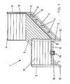
- Fig. 4 eine Explosionsdarstellung des hinteren Teils eines Fahrzeugs und eines Auflaufrahmens,
- Fig. 5 eine Vorderansicht der Aufnahmevorrichtung gemäß Fig. 1,
- Fig. 6 eine Seitenansicht der in Fig. 5 dargestellten Aufnahmevorrichtung und
- Fig. 7 eine Ansicht des freien Endes des am Laufschlitten schwenkbar gelagerten Arms mit dem daran angebrachten Haken.
- 1 is a perspective view of an embodiment of an interchangeable container with a hanging device,
- 2 is a side view of a first embodiment of a vehicle for loading with the swap body,
- 3 shows a plan view of the vehicle according to FIG. 2,
- 4 is an exploded view of the rear part of a vehicle and an overrun frame;
- 5 shows a front view of the receiving device according to FIG. 1,
- Fig. 6 is a side view of the receiving device shown in Fig. 5 and
- Fig. 7 is a view of the free end of the arm pivotally mounted on the carriage with the hook attached.
Der in Fig. 1 dargestellte Wechselbehälter 1 besteht aus einer in sich starren Rahmenkonstruktion, die an ihren Ecken zwei vordere Pfosten 2 und zwei hintere Pfosten 3 enthält, wobei die vorderen und hinteren Pfosten an jeder Seite durch zwei Längsholme 4 und 5 miteinander verbunden sind, von denen einer in Höhe des Bodens 6 und der zweite unterhalb des Bodens angeordnet und mit dem ersten Holm 4 durch Verbindungsstreben 7 verbunden ist. Die an den beiden Seiten des Behälters befindlichen Längsholme sind durch Querholme miteinander verbunden, von denen nur die Holme 8 und 9 sichtbar sind. Durch diese Rahmenkonstruktion kann der Behälter beliebig hinsichtlich der Wände umgerüstet werden. Bei dem dargestellten Ausführungsbeispiel ist an den Pfosten 2 eine Vorderwand 10 und an den Pfosten 3 eine Rückwand 11 angebracht. Die Wände 10, 11 und der Boden 6 bestehen dabei aus einzelnen Bohlen, die am Traggerüst befestigt sind. In gleicher Weise können auch nicht dargestellte Seitenwände an der Rahmenkonstruktion angebracht werden, so daß je nach Einsatzzweck die benötigte Anzahl von Wänden vom Benutzer selbst angebracht werden kann. Erforderlichenfalls können auch alle Wände abgenommen werden, so daß der Behälter nach Art einer Pritsche benutzbar ist. In diesem Fall kann es zweckmäßig sein, die Pfosten 2 und 3 in Höhe des Bodens 6 mit arretierbaren Klappscharnieren zu versehen, die ein Umklappen der Pfosten in eine horizontale Lage auf den Boden 6 zulassen, so daß sie nicht mehr im Wege sind.The swap body 1 shown in Fig. 1 consists of a rigid frame construction which contains at its corners two
Normalerweise ruht der Behälter auf den unteren Längsstreben 5. Dann können die Längsstreben 5 auf den Laufrollen des Fahrzeuges beim Aufziehen des Behälters auf das Fahrzeug geführt werden. Es können aber auch an den Pfosten 2 Standfüße 12 angebracht werden, wobei es zweckmäßig ist, am hinteren Ende der unteren Längsholme 5 je eine Rolle 13 anzubringen, so daß der hintere Teil des Behälters beim Aufladen auf dem Boden rollt und nicht schleift. Wenn Standfüße vorgesehen sind, ist es zweckmäßig, die Laufrollen 22 am Fahrzeug so anzubringen, daß die Unterseite des Bodens auf ihnen geführt wird. Zu diesem Zweck können an der Unterseite des Bodens 6 Schienen 15 vorgesehen werden.The container normally rests on the lower
Die Längsholmpaare 4 und 5 haben einen solchen seitlichen Abstand voneinander, daß die durch sie unterhalb des Bodens 6 gebildeten Verlängerungen die Fahrzeugbereifung übergreifen, wenn der Behälter sich auf dem Fahrzeug befindet, so daß die volle zulässige Fahrzeugbreite für den Behälter ausnutzbar ist.The longitudinal beam pairs 4 and 5 have such a lateral distance from one another that the extensions formed by them below the
Es ist ersichtlich, daß mit der dargestellten Behälterkonstruktion der Kippwinkel erheblich geringer als bei bekannten Konstruktionen gehalten werden kann, weil nur noch die Höhendifferenz zwischen dem Behälterboden und dem Auflaufrahmen überwunden werden muß.It can be seen that with the container construction shown, the tilt angle can be kept considerably smaller than in known constructions, because only the height difference between the container bottom and the run-up frame has to be overcome.
Dadurch, daß der Boden 6 auf einem höheren Niveau als sonst üblich liegt, kann eine Aufnahmevorrichtung 14 in der Mitte am vorderen Querholm angebracht und als Fangvorrichtung für einen Haken ausgebildet werden. Dies wird noch anhand von Fig. 5 und 6 weiter unten näher erläutert.Because the
Bei dem dargestellten Ausführungsbeispiel werden der Boden 6 und die Wände 10 und 11 durch Bohlen gebildet, die je nach Verwendungszweck des Behälters aus Eisen, Leichtmetall oder auch aus Holz bestehen können.In the illustrated embodiment, the
Stattdessen können Boden und Wände auch aus durchgehenden Platten bestehen. Dabei ist es auch möglich, in Verbindung mit den oben erwähnten Klappscharnieren an den Stützen 2 und 3 die gesamte Vorder- und Rückwand einklappbar auszubilden, so daß der Behälter leicht stapelbar ist. Schließlich ist auch die Anordnung einer Deckenplatte bzw. einer Abdeckplane am oberen Ende des Behälters möglich, so daß ein allseits geschlossener Container gebildet wird.Instead, the floor and walls can consist of continuous panels. It is also possible to form the entire front and rear wall in connection with the above-mentioned folding hinges on the
In Fig. 2 und 3 ist eine Ausführungsform eines Fahrzeuges zum Auf- und Abladen des erfindungsgemäßen Wechselbehälters dargestellt. Das Fahrzeug besteht bei diesem Ausführungsbeispiel aus einem Anhänger, der einen im wesentlichen rechtwinkligen Chassisrahmen 16 aufweist und an seiner Vorderseite mittig mit einer Deichsel 17 versehen ist, die mit einem Zugfahrzeug kuppelbar ist. Natürlich kann der Chassisrahmen 16 auch Teil eines Zugfahrzeuges sein.2 and 3, an embodiment of a vehicle for loading and unloading the swap body according to the invention is shown. In this exemplary embodiment, the vehicle consists of a trailer which has a substantially
Der Chassisrahmen 16 stützt sich vorn auf dem Boden über einen Standfuß 18 und hinten über Zwillingsreifen 19 ab. An seinen Seiten besitzt der Chassisrahmen 16 Längsträger 20, die am hinteren Ende des Chassisrahmens nach unten rechtwinklig abgewinkelt und mit einem schräg nach oben geneigten Langloch 21 versehen sind. Unterhalb des Langloches 21 ist an jedem der beiden Längsträger 20 eine Laufrolle 22 derart befestigt, daß der Abstand der beiden Laufrollen 22 größer ist als der Außenabstand der Zwillingsreifen 19.The
Mit dem Chassisrahmen 16 ist über eine in den Langlöchern 21 geführte Schwenkachse 23 ein Auflaufrahmen 24 schwenkbar verbunden. Der Auflaufrahmen ist U-förmig ausgebildet, wobei die Schenkel zwei Längsträger 25 und die Basis einen Querträger 26 bilden. An ihren hinteren Enden sind die Längsträger 25 des Auflaufrahmens 24 schräg nach unten abgewinkelt und daran anschließend mit einer rechtwinkligen Lasche 27 versehen, die ihrerseits eine Bohrung 28 zur Aufnahme der Schwenkachse 23 aufweist.A
Zwischen den beiden Längsträgern 25 des Auflaufrahmens 24 ist ein zweiachsiger Laufschlitten 29 verschiebbar geführt, wobei die Räder 30 des Laufschlittens 29 in den Längsträgern 25 laufen. Der Laufschlitten 29 ist an seinem der Schwenkachse 23 zugewandten Ende mit einem Arm 31 versehen, der aus einer Stellung, in der er auf dem Laufschlitten 29 aufliegt (Fig. 3) derart ausschwenkbar ist, daß er bei Anordnung des Laufschlittens im abgewinkelten Endbereich in Höhe der Aufnahmevorrichtung 14 eines auf dem Boden stehenden Wechselbehälters liegt. Am Ende des Armes 31 ist ein Haken 32 angebracht, der das fahrzeugseitige Kupplungselement für die Aufnahmevorrichtung 14 am Behälter 1 bildet.A two-
Am Haken 32 greift ein als Zugelement dienendes Stahlseil 33 an, das mit der Seiltrommel 34 der Aufwickelvorrichtung verbunden ist. Im Vergleich mit bekannten Systemen ergibt sich durch die Verwendung des Laufschlittens der Vorteil, daß nur ein Zugseil verwendet zu werden braucht.A
Wenn nun der erfindungsgemäße Wechselbehälter auf das Fahrzeug aufgeladen werden soll, wird das Fahrzeug, das - wie erwähnt - neben der in Fig. 2 und 3 dargestellten Ausführungsform als Anhänger auch ein mit Fahrerkabine, Vorderachse und Motor ausgerüsteter Lastkraftwagen sein kann, zunächst rückwärts vor den Wechselbehälter gefahren, und der Auflaufrahmen 24 wird vom Chassisrahmen 16 aufwärts geschwenkt. Als Schwenkmechanismus kann beispielsweise in bekannter Weise ein nicht dargestellter, zwischen dem Auflaufrahmen 24 und dem Chassisrahmen 16 angeordneter Hydraulikkolben dienen. Gleichzeitig mit dem Hochschwenken des Auflaufrahmens wird die Seiltrommel 34 entriegelt, so daß der Laufschlitten 29 nach dem Schwerkraftprinzip durch sein Eigengewicht angetrieben aus seiner Ausgangsstellung nahe dem Querträger 26 bis in den abgewinkelten Endbereich der Längsträger 25 gleitet. Die Länge dieser Endbereiches entspricht dabei zweckmäßigerweise dem Mittenabstand der beiden Laufschlittenachsen, wodurch erreicht wird, daß der Laufschlitten mit seinen der Seiltrommel zugewandten Rädern 30 nicht in den abgewinkelten Bereich gelangen kann und damit nach Art eines Anschlages in der in Fig. 2 gezeigten Endstellung selbständig festgelegt wird. Durch die Entriegelung der Seiltrommel wird das mit dem Laufschlitten über dessen Arm 31 verbundene Stahlseil 33 bei der Bewegung des Laufschlittens 29 von der Seiltrommel abgewickelt. Hat der Laufschlitten seine Endposition erreicht, schwenkt auch der Arm 31 von seiner in Fig. 3 dargestellten Ruhelage in die in Fig. 2 dargestellte Betriebslage aus. In dieser Lage entspricht die Höhe des Hakens 32 der Höhe der am Wechselbehälter installierten Aufnahmevorrichtung 14.If the swap body according to the invention is now to be loaded onto the vehicle, the vehicle, which - as mentioned - in addition to the embodiment shown in FIGS. 2 and 3 as a trailer can also be a truck equipped with a driver's cab, front axle and engine, is first reversed in front of the Swap body driven, and the
Um nun ein vollautomatisches Einkuppeln des Hakens 32 in die Aufnahmevorrichtung 14 zu erreichen, wird das Fahrzeug mit dem in die untere Position bewegten Laufschlitten an den Wechselbehälter 1 herangefahren, bis die Kupplung erfolgt ist. Anschließend wird die Seiltrommel 34 betätigt, wodurch das Stahlseil 33 angezogen wird und den mit dem Stahlseil verbundenen Arm 31 des Laufschlittens 29 in seine Ausgangslage zurück auf den Laufschlitten schwenkt, wobei der Haken 32 des Arms 31 auf dem der Seiltrommel zugewandten Ende des Laufschlittens zur Auflage kommt. Zugleich wird durch diese Schwenkbewegung der über die Aufnahmevorrichtung 14 mit dem Arm 31 fest verbundene Behälter 1 an seinem stirnwandseitigen Ende angehoben und auf das Fahrzeug gezogen. Dabei kommen die Unterkanten der unteren Längsholme 5 auf den Laufrollen 22 zur Auflage. Wird nun das Stahlseil 33 weiter auf die Seiltrommel 34 aufgewickelt, bewegt sich der Laufschlitten 29 aus dem abgewinkelten Endbereich der beiden Längsträger 25 zurück in den geradlinigen Bereich. Dabei wird der Wechselbehälter gleichzeitig weiter auf den Auflaufrahmen 24 gezogen und der Laufschlitten 29 legt sich direkt unter den Boden 6 des Wechselbehälters 1. Während des Aufziehens des Wechselbehälters durch den Laufschlitten werden die Unterkanten der Längsholme 5 auf den Laufrollen 22 geführt. Ist der Aufladevorgang beendet, d. h. der Laufschlitten befindet sich wieder in seiner Ausgangsstellung vor dem Querträger 26, kann der Auflaufrahmen auf den Chassisrahmen 16 abgesenkt werden, wobei die beiden die Fahrzeugbereifung 19 übergreifenden Verlängerungen des Tragrahmens die Absenkbewegung des Auflaufrahmens nicht behindern.To now fully automatic engagement of the To reach
Durch die Führung der Schwenkachse 23 in den beiden Langlöchern 21 wird erreicht, daß der gesamte Auflaufrahmen 24 auf dem Chassisrahmen 16 seitlich gegenüber der Fahrzeuglängsachse verschwenkbar ist. Dadurch kann auch ein Wechselbehälter, der nicht genau in Verlängerung der Fahrzeuglängsachse steht, noch problemlos auf den Auflaufrahmen aufgezogen werden. Dabei verschwenkt zunächst der Auflaufrahmen in die Wechselbehälter-Längsrichtung und nimmt erst nach Abheben des Behälters vom Boden durch eine Ausgleichsbewegung in den Langlöchern 21 wieder seine parallel zur Fahrzeuglängsachse ausgerichtete Lage ein.By guiding the
Die Laufrollen 22 können anstatt der Anordnung an den beiden Längsträgern des Chassisrahmens auch in nicht dargestellter Weise an den beiden Längsträgern 25 des Auflaufrahmens 24 an deren Übergang zu ihrem abgewinkelten Endbereich befestigt werden, wobei dann nicht die unteren Längsholme 5, sondern die Unterkante des Bodens 6 beim Aufladevorgang über die Laufrollen geführt wird.Instead of the arrangement on the two longitudinal beams of the chassis frame, the
In Fig. 4 ist eine Explosionsdarstellung einer zweiten Ausführungsform des hinteren Endes des Fahrzeugs und des Auflaufrahmens dargestellt. Die Funktionsweise im Betrieb erfolgt dabei in gleicher Weise wie bei dem anhand von Fig. 1 bis 3 beschriebenen Ausführungsbeispiel. Gleiche und funktionsmäßig gleiche Teile dieser zweiten Ausführungsform sind dabei mit gleichen Bezugsziffern wie in Fig. 2 und 3 versehen.4 shows an exploded view of a second embodiment of the rear end of the vehicle and the overrun frame. The operation in operation takes place in the same way as in the embodiment described with reference to FIGS. 1 to 3. Identical and functionally identical parts of this second embodiment are provided with the same reference numerals as in FIGS. 2 and 3.
Die Längsträger 20 des Chassisrahmens 16 befinden sich oberhalb der Fahrzeugbereifung und sind am Fahrzeugheck vertikal nach unten abgewinkelt. Der Auflaufrahmen befindet sich in abgesenkter Position innerhalb des Chassisrahmens, so daß eine ebene, aus dem Chassisrahmen 16 und dem Auflaufrahmen 26 gebildete Oberfläche vorhanden ist. Die Laufrollen 22 sind am Übergang der Längsträger 20 des Chassisrahmens 16 in ihren abgewinkelten Bereich angeordnet, und der Auflaufrahmen 24 ist wiederum um eine in zwei schräg nach oben weisenden Langlöchern 21 geführte Schwenkachse 23 schwenkbar. Dabei sind die beiden Langlöcher 21 in Flacheisen 35 angebracht, die senkrecht auf einem zwischen den beiden Längsträgern 20 des Chassisrahmens angeordneten Querträger 36 montiert sind. Auf diesem Querträger 36 liegt der Auflaufrahmen mit einem an dessen Längsträger 25 anschließenden Rahmen 37 auf. Dieser Rahmen ist mit zwei Flacheisen 38 verbunden, die die Flacheisen 35 auf dem Querträger 36 übergreifen und eine Bohrung 39 aufweisen, durch die ein nicht dargestellter Bolzen als Schwenkachse 23 in die Langlöcher 21 einführbar ist.The
Im Betrieb dieser Ausführungsform wird der Behälter mit der Unterseite seines Bodens auf die beiden Laufrollen 22 gehoben, deren gegenseitiger Abstand dem Innenabstand der Längsholme 4, 5 des Wechselbehälters 1 entspricht. Dadurch wird in vorteilhafter Weise erreicht, daß während des Aufladens des Behälters die Längsholme eng an den Laufrollen anliegen und ein seitliches Verschwenken des Wechselbehälters weitgehend ausgeschlossen ist.In the operation of this embodiment, the container is lifted with the underside of its bottom onto the two
In Fig. 5 und 6 ist eine Detailansicht der Aufnahmevorrichtung 14 dargestellt. Die Aufnahmevorrichtung besteht im wesentlichen aus einem U-förmigen Rahmenprofil, das aus einer Basisplatte 40 und zwei seitlichen Schenkelplatten 41 gebildet wird. Das Rahmenprofil ist mittig zwischen den beiden Pfosten 2 am Querholm 6 in geeigneter Weise befestigt, z. B. verschweißt. An der Basisplatte 40 sind innen zwei Bleche 43 derart angeordnet, daß sich aus den Blechen 43 eine dachförmige Konstruktion mit einem Zwischenraum 42 am First ergibt. Zwischen den freien Enden der beiden Schenkelplatten 41 ist horizontal eine Achse 44 befestigt, deren Außendurchmesser im mittleren Bereich unter Bildung zweier Schultern 45 und 46 verringert ist. Zwischen der dachförmigen Konstruktion und der Achse 44 ist ferner noch parallel zur Achse 44 ein weiteres Flacheisen 47 befestigt.5 and 6, a detailed view of the receiving
Fig. 7 zeigt eine Detailansicht des am Ende des Arms 31 angebrachten Hakens 32. Der Haken ist annähernd U-förmig ausgebildet und besteht ebenfalls aus einem Flacheisen. Die Basis 46 des Hakens verläuft quer zum Arm 31. Der obere Schenkel 49 verläuft gerade, während der untere Schenkel 50 eine runde Öse 51 bildet, deren Innendurchmesser dem Durchmesser des mittleren Teils der Achse 44 entspricht.Fig. 7 shows a detailed view of the end of the
Beim Kupplungsvorgang erfaßt die Öse 51 den mittleren Teil der Achse 44, wobei der Schenkel 49 unmittelbar unterhalb des Zwischenraums 42 zu liegen kommt. Die beiden Bleche 43 sorgen dafür, daß der Haken 32 auch wirklich mit der Mitte der Achse 44 in Eingriff kommt. Wird nun das Zugelement eingefahren, schwenkt der Arm 31 - wie oben beschrieben - auf den Laufschlitten 29 herum, wobei sich der Haken 32 auf der Achse 44 um etwa 180° dreht. Mit der Schwenkung des Arms 31 wird zugleich der Behälter 1 angehoben und anschließend bei weiterem Einfahren des Zugelements auf den Auflaufrahmen hochgezogen. Beim Schwenkvorgang arretiert das Flacheisen 47 den Haken 32.During the coupling process, the
Claims (17)
Applications Claiming Priority (2)
| Application Number | Priority Date | Filing Date | Title |
|---|---|---|---|
| DE3407568 | 1984-03-01 | ||
| DE19843407568 DE3407568A1 (en) | 1984-03-01 | 1984-03-01 | INTERCHANGEABLE TRANSPORT SYSTEM |
Publications (2)
| Publication Number | Publication Date |
|---|---|
| EP0154891A1 EP0154891A1 (en) | 1985-09-18 |
| EP0154891B1 true EP0154891B1 (en) | 1987-11-04 |
Family
ID=6229304
Family Applications (1)
| Application Number | Title | Priority Date | Filing Date |
|---|---|---|---|
| EP85102167A Expired EP0154891B1 (en) | 1984-03-01 | 1985-02-28 | Interchangeable container transport system |
Country Status (2)
| Country | Link |
|---|---|
| EP (1) | EP0154891B1 (en) |
| DE (2) | DE3407568A1 (en) |
Families Citing this family (3)
| Publication number | Priority date | Publication date | Assignee | Title |
|---|---|---|---|---|
| US4911318A (en) * | 1988-12-22 | 1990-03-27 | American Coastal Industries | Air transportable container adjunct |
| EP2529018B1 (en) | 2009-12-30 | 2016-06-22 | Pioneer Hi-Bred International, Inc. | Methods and compositions for the introduction and regulated expression of genes in plants |
| DE102021132685A1 (en) | 2021-12-10 | 2023-06-15 | Carl-Ludwig Begemann | Container changing device and a container or load carrier intended for this purpose |
Family Cites Families (6)
| Publication number | Priority date | Publication date | Assignee | Title |
|---|---|---|---|---|
| GB763050A (en) * | 1952-10-30 | 1956-12-05 | George Roland Hill | Improvements in or relating to vehicle bodies |
| US3399795A (en) * | 1966-08-15 | 1968-09-03 | Harsco Corp | Loading apparatus for demountable vehicle bodies |
| US4058231A (en) * | 1975-08-21 | 1977-11-15 | Autolava Oy | Apparatus for moving an exchangeable platform or a container on to and off of a tipping frame of a lorry, trailer, or the like |
| FI55313C (en) * | 1977-06-07 | 1979-07-10 | Multilift Oy | GRIPANORDNING VID EN LASTBILS VAEXELFLAKSANORDNING |
| AU4163978A (en) * | 1977-11-17 | 1979-05-24 | Brimec Uk Ltd | Demountable bodies |
| DE2758693A1 (en) * | 1977-12-29 | 1979-07-12 | Toussaint & Hess Gmbh | Container pick=up and tipping mechanism - has support and tipping frame extending over entire length of vehicle chassis with initial upward movement |
-
1984
- 1984-03-01 DE DE19843407568 patent/DE3407568A1/en not_active Withdrawn
-
1985
- 1985-02-28 EP EP85102167A patent/EP0154891B1/en not_active Expired
- 1985-02-28 DE DE8585102167T patent/DE3560871D1/en not_active Expired
Also Published As
| Publication number | Publication date |
|---|---|
| EP0154891A1 (en) | 1985-09-18 |
| DE3560871D1 (en) | 1987-12-10 |
| DE3407568A1 (en) | 1985-09-12 |
Similar Documents
| Publication | Publication Date | Title |
|---|---|---|
| DE2630774A1 (en) | FORKLIFT TRUCK AND METHOD AND DEVICE FOR STORING THESES | |
| EP2443005B1 (en) | Transport system | |
| DE3033308A1 (en) | UNLOADING AND LOADING BRIDGE WITH SWIVEL LOCK | |
| EP3620327B1 (en) | Hook-lift vehicle and container for a hook-lift vehicle | |
| DE2457958A1 (en) | ADDITIONAL DEVICE FOR VEHICLES FOR TRANSPORTING CONTAINERS | |
| DE4335456C2 (en) | Trucks for the transportation of goods | |
| DE1655728A1 (en) | Device for lifting and transporting loads | |
| DE1194715B (en) | Device for loading and unloading large, box-like containers on vehicles | |
| DE2228764A1 (en) | Folding wall for dump rear tipper vehicle | |
| DE102004018910A1 (en) | Trailer for use at airport or in factory, comprising lifting and lowering unit for transported goods | |
| EP0154891B1 (en) | Interchangeable container transport system | |
| DE2947904C2 (en) | Device for the optional depositing of transportable containers, machines or devices on the tiltable loading platform of a truck or on the ground | |
| DE2241784C2 (en) | ||
| DE1680152C3 (en) | Device on motor vehicles for picking up, setting down and tipping containers | |
| DE2647227C2 (en) | Handling device for lifting and tipping freight containers for bulk goods | |
| DE2319652A1 (en) | EQUIPMENT FOR LOADING AND UNLOADING A CONTAINER WITH A SEMI-TRAILER | |
| DE3144607A1 (en) | "SILO OR CONTAINER MOVABLE WITH A TRUCK VEHICLE" | |
| DE3633862A1 (en) | Container vehicle | |
| EP0127141A1 (en) | Load carrier and lifting device for a vehicle | |
| DE102017101368A1 (en) | Tugger trailer for ground scooter | |
| DE3139141A1 (en) | Transportation vehicle | |
| DE3315813A1 (en) | ATTACHMENT BODY FOR THE THREE-POINT LIFTING DEVICE OF A TRACTOR | |
| DE19542816A1 (en) | Transport vehicle, especially heavy goods vehicle | |
| DE60201793T2 (en) | Trailer with lowered loading area, in particular for the transport of agricultural machines | |
| DE3338538C2 (en) | Movable load carrier in the form of a vehicle trailer |
Legal Events
| Date | Code | Title | Description |
|---|---|---|---|
| PUAI | Public reference made under article 153(3) epc to a published international application that has entered the european phase |
Free format text: ORIGINAL CODE: 0009012 |
|
| AK | Designated contracting states |
Designated state(s): BE DE FR GB IT NL |
|
| 17P | Request for examination filed |
Effective date: 19860313 |
|
| 17Q | First examination report despatched |
Effective date: 19870120 |
|
| GRAA | (expected) grant |
Free format text: ORIGINAL CODE: 0009210 |
|
| AK | Designated contracting states |
Kind code of ref document: B1 Designated state(s): BE DE FR GB IT NL |
|
| REF | Corresponds to: |
Ref document number: 3560871 Country of ref document: DE Date of ref document: 19871210 |
|
| GBT | Gb: translation of ep patent filed (gb section 77(6)(a)/1977) | ||
| ITF | It: translation for a ep patent filed |
Owner name: UFFICIO BREVETTI RICCARDI & C. |
|
| ET | Fr: translation filed | ||
| PLBE | No opposition filed within time limit |
Free format text: ORIGINAL CODE: 0009261 |
|
| STAA | Information on the status of an ep patent application or granted ep patent |
Free format text: STATUS: NO OPPOSITION FILED WITHIN TIME LIMIT |
|
| 26N | No opposition filed | ||
| ITTA | It: last paid annual fee | ||
| PGFP | Annual fee paid to national office [announced via postgrant information from national office to epo] |
Ref country code: NL Payment date: 19920229 Year of fee payment: 8 |
|
| PG25 | Lapsed in a contracting state [announced via postgrant information from national office to epo] |
Ref country code: NL Effective date: 19930901 |
|
| NLV4 | Nl: lapsed or anulled due to non-payment of the annual fee | ||
| PGFP | Annual fee paid to national office [announced via postgrant information from national office to epo] |
Ref country code: GB Payment date: 19940210 Year of fee payment: 10 |
|
| PG25 | Lapsed in a contracting state [announced via postgrant information from national office to epo] |
Ref country code: GB Effective date: 19950228 |
|
| PGFP | Annual fee paid to national office [announced via postgrant information from national office to epo] |
Ref country code: BE Payment date: 19950306 Year of fee payment: 11 |
|
| GBPC | Gb: european patent ceased through non-payment of renewal fee |
Effective date: 19950228 |
|
| PG25 | Lapsed in a contracting state [announced via postgrant information from national office to epo] |
Ref country code: BE Effective date: 19960228 |
|
| PGFP | Annual fee paid to national office [announced via postgrant information from national office to epo] |
Ref country code: FR Payment date: 19960228 Year of fee payment: 12 |
|
| PGFP | Annual fee paid to national office [announced via postgrant information from national office to epo] |
Ref country code: DE Payment date: 19960426 Year of fee payment: 12 |
|
| BERE | Be: lapsed |
Owner name: BEGEMANN CARL-LUDWIG Effective date: 19960228 |
|
| PG25 | Lapsed in a contracting state [announced via postgrant information from national office to epo] |
Ref country code: FR Effective date: 19971030 |
|
| PG25 | Lapsed in a contracting state [announced via postgrant information from national office to epo] |
Ref country code: DE Effective date: 19971101 |
|
| REG | Reference to a national code |
Ref country code: FR Ref legal event code: ST |