EP0154781A2 - Verbinder für optische Wellenleiter - Google Patents
Verbinder für optische Wellenleiter Download PDFInfo
- Publication number
- EP0154781A2 EP0154781A2 EP85100800A EP85100800A EP0154781A2 EP 0154781 A2 EP0154781 A2 EP 0154781A2 EP 85100800 A EP85100800 A EP 85100800A EP 85100800 A EP85100800 A EP 85100800A EP 0154781 A2 EP0154781 A2 EP 0154781A2
- Authority
- EP
- European Patent Office
- Prior art keywords
- plug member
- waveguide
- sleeve
- passageway
- receptacle
- Prior art date
- Legal status (The legal status is an assumption and is not a legal conclusion. Google has not performed a legal analysis and makes no representation as to the accuracy of the status listed.)
- Granted
Links
- 230000003287 optical effect Effects 0.000 title claims abstract description 39
- 230000014759 maintenance of location Effects 0.000 claims abstract description 37
- 230000002401 inhibitory effect Effects 0.000 claims abstract description 3
- 239000000835 fiber Substances 0.000 claims description 44
- 238000003780 insertion Methods 0.000 claims description 19
- 230000037431 insertion Effects 0.000 claims description 19
- 239000013307 optical fiber Substances 0.000 description 13
- 239000000463 material Substances 0.000 description 6
- 230000008878 coupling Effects 0.000 description 5
- 238000010168 coupling process Methods 0.000 description 5
- 238000005859 coupling reaction Methods 0.000 description 5
- 239000004033 plastic Substances 0.000 description 4
- 229920003023 plastic Polymers 0.000 description 4
- 239000004065 semiconductor Substances 0.000 description 4
- 239000000853 adhesive Substances 0.000 description 3
- 230000001070 adhesive effect Effects 0.000 description 3
- 238000005516 engineering process Methods 0.000 description 3
- 230000013011 mating Effects 0.000 description 3
- 238000000034 method Methods 0.000 description 3
- 238000002788 crimping Methods 0.000 description 2
- 238000009826 distribution Methods 0.000 description 2
- 238000004519 manufacturing process Methods 0.000 description 2
- 230000036961 partial effect Effects 0.000 description 2
- 238000005498 polishing Methods 0.000 description 2
- 230000000717 retained effect Effects 0.000 description 2
- 239000002131 composite material Substances 0.000 description 1
- 239000004020 conductor Substances 0.000 description 1
- 238000005520 cutting process Methods 0.000 description 1
- 230000007246 mechanism Effects 0.000 description 1
- 238000004806 packaging method and process Methods 0.000 description 1
- 230000000149 penetrating effect Effects 0.000 description 1
- 230000035515 penetration Effects 0.000 description 1
- 230000002829 reductive effect Effects 0.000 description 1
Images

Classifications
-
- G—PHYSICS
- G02—OPTICS
- G02B—OPTICAL ELEMENTS, SYSTEMS OR APPARATUS
- G02B6/00—Light guides; Structural details of arrangements comprising light guides and other optical elements, e.g. couplings
- G02B6/24—Coupling light guides
- G02B6/36—Mechanical coupling means
- G02B6/38—Mechanical coupling means having fibre to fibre mating means
- G02B6/3807—Dismountable connectors, i.e. comprising plugs
- G02B6/389—Dismountable connectors, i.e. comprising plugs characterised by the method of fastening connecting plugs and sockets, e.g. screw- or nut-lock, snap-in, bayonet type
- G02B6/3893—Push-pull type, e.g. snap-in, push-on
-
- G—PHYSICS
- G02—OPTICS
- G02B—OPTICAL ELEMENTS, SYSTEMS OR APPARATUS
- G02B6/00—Light guides; Structural details of arrangements comprising light guides and other optical elements, e.g. couplings
- G02B6/24—Coupling light guides
- G02B6/36—Mechanical coupling means
- G02B6/38—Mechanical coupling means having fibre to fibre mating means
- G02B6/3807—Dismountable connectors, i.e. comprising plugs
- G02B6/3809—Dismountable connectors, i.e. comprising plugs without a ferrule embedding the fibre end, i.e. with bare fibre end
-
- G—PHYSICS
- G02—OPTICS
- G02B—OPTICAL ELEMENTS, SYSTEMS OR APPARATUS
- G02B6/00—Light guides; Structural details of arrangements comprising light guides and other optical elements, e.g. couplings
- G02B6/24—Coupling light guides
- G02B6/36—Mechanical coupling means
- G02B6/38—Mechanical coupling means having fibre to fibre mating means
- G02B6/3807—Dismountable connectors, i.e. comprising plugs
- G02B6/381—Dismountable connectors, i.e. comprising plugs of the ferrule type, e.g. fibre ends embedded in ferrules, connecting a pair of fibres
- G02B6/3826—Dismountable connectors, i.e. comprising plugs of the ferrule type, e.g. fibre ends embedded in ferrules, connecting a pair of fibres characterised by form or shape
- G02B6/3831—Dismountable connectors, i.e. comprising plugs of the ferrule type, e.g. fibre ends embedded in ferrules, connecting a pair of fibres characterised by form or shape comprising a keying element on the plug or adapter, e.g. to forbid wrong connection
-
- G—PHYSICS
- G02—OPTICS
- G02B—OPTICAL ELEMENTS, SYSTEMS OR APPARATUS
- G02B6/00—Light guides; Structural details of arrangements comprising light guides and other optical elements, e.g. couplings
- G02B6/24—Coupling light guides
- G02B6/36—Mechanical coupling means
- G02B6/38—Mechanical coupling means having fibre to fibre mating means
- G02B6/3807—Dismountable connectors, i.e. comprising plugs
- G02B6/3833—Details of mounting fibres in ferrules; Assembly methods; Manufacture
- G02B6/3834—Means for centering or aligning the light guide within the ferrule
- G02B6/3838—Means for centering or aligning the light guide within the ferrule using grooves for light guides
-
- G—PHYSICS
- G02—OPTICS
- G02B—OPTICAL ELEMENTS, SYSTEMS OR APPARATUS
- G02B6/00—Light guides; Structural details of arrangements comprising light guides and other optical elements, e.g. couplings
- G02B6/24—Coupling light guides
- G02B6/36—Mechanical coupling means
- G02B6/38—Mechanical coupling means having fibre to fibre mating means
- G02B6/3807—Dismountable connectors, i.e. comprising plugs
- G02B6/3873—Connectors using guide surfaces for aligning ferrule ends, e.g. tubes, sleeves, V-grooves, rods, pins, balls
- G02B6/3874—Connectors using guide surfaces for aligning ferrule ends, e.g. tubes, sleeves, V-grooves, rods, pins, balls using tubes, sleeves to align ferrules
- G02B6/3878—Connectors using guide surfaces for aligning ferrule ends, e.g. tubes, sleeves, V-grooves, rods, pins, balls using tubes, sleeves to align ferrules comprising a plurality of ferrules, branching and break-out means
- G02B6/3879—Linking of individual connector plugs to an overconnector, e.g. using clamps, clips, common housings comprising several individual connector plugs
-
- G—PHYSICS
- G02—OPTICS
- G02B—OPTICAL ELEMENTS, SYSTEMS OR APPARATUS
- G02B6/00—Light guides; Structural details of arrangements comprising light guides and other optical elements, e.g. couplings
- G02B6/24—Coupling light guides
- G02B6/36—Mechanical coupling means
- G02B6/38—Mechanical coupling means having fibre to fibre mating means
- G02B6/3807—Dismountable connectors, i.e. comprising plugs
- G02B6/3887—Anchoring optical cables to connector housings, e.g. strain relief features
- G02B6/3888—Protection from over-extension or over-compression
-
- G—PHYSICS
- G02—OPTICS
- G02B—OPTICAL ELEMENTS, SYSTEMS OR APPARATUS
- G02B6/00—Light guides; Structural details of arrangements comprising light guides and other optical elements, e.g. couplings
- G02B6/24—Coupling light guides
- G02B6/36—Mechanical coupling means
- G02B6/38—Mechanical coupling means having fibre to fibre mating means
- G02B6/3807—Dismountable connectors, i.e. comprising plugs
- G02B6/3897—Connectors fixed to housings, casing, frames or circuit boards
-
- G—PHYSICS
- G02—OPTICS
- G02B—OPTICAL ELEMENTS, SYSTEMS OR APPARATUS
- G02B6/00—Light guides; Structural details of arrangements comprising light guides and other optical elements, e.g. couplings
- G02B6/24—Coupling light guides
- G02B6/42—Coupling light guides with opto-electronic elements
- G02B6/4292—Coupling light guides with opto-electronic elements the light guide being disconnectable from the opto-electronic element, e.g. mutually self aligning arrangements
Definitions
- the present invention relates to optical waveguide connections and in particular to optical waveguide connectors comprising a retention sleeve that is secured onto an optical waveguide and into a receptacle or plug component which functions to axially locate a single optical waveguide fibre on the axis of a receptacle bore.
- a further problem confronted by fibre optic connector technology is attributable to the fact that a variety of cable sizes exists in the industry.
- the relatively large plastic fibre used in certain systems can range in size between 41 to 102 thousandths of a centimeter (16 to 40 thousandths of an inch). Consequently, the connectors for terminating these fibres must accommodate this wide range of potential fibre sizes, which further complicates the achievement of a suitable connectcr system.
- the outer diameter of jacket which protects the fibres in a cabling structure, can also vary.
- Presently available connectors because of their alignment techniques, have difficulty in accommodating the termination of the wide range of cable sizes which a user must confront in the optical cable world.
- a member for coaxially locating an optical waveguide within a bore of a connector comprising a body for insertion into the bore, the body having an axial passageway for receiving the waveguide, a forward alignment nose portion having an opening therethrough communicating with the passageway, and a rearward passageway portion for passage of the waveguide.
- the nose portion serves to centre the waveguide which is secured to the body by crimping.
- a retention member for securing a fibre optic waveguide in the bore of a receptacle which comprises a U-shaped ferrule adapted to be crimped about the waveguide into a tubular body.
- the ferrule is formed with inwardly directed tines which bite into the waveguide sheath on crimping, and with outwardly and rearwardly directed tines for engaging a forward facing shoulder of the receptacle to retain the ferrule therein.
- the plug member for coaxially locating an optical waveguide of the type comprising a centre waveguide fibre and an outer jacket layer within a bore of a receptacle member
- the plug member comprises an elongate plug body for insertion within the bore, the body having an axial passageway for receiving the optical waveguide, a forward alignment nose portion having an opening therethrough communicating with the passageway, and a rearward passageway portion for passage of the waveguide to the nose portion characterised in that a retention sleeve is provided for receiving and securing the waveguide and for insertion and retention within the rear passageway portion, the retention member having tines for inhibiting rearward withdrawal of the optical waveguide from the plug members, the opening in the nose portion being defined by opposed V-shaped notch surfaces separated by a transverse slot extending through the nose portion whereby on insertion of the waveguide and the retention sleeve into the passageway
- the retention member is that disclosed and claimed in our copending European Patent 'Application EP-A-82301066.5 from which the present application is divided that is to say the retention member has a first series of inwardly directed tines angularly spaced around the sleeve for engaging the optical waveguide and a second series of outwardly directed tines extending rearwardly for engaging the rearward passageway portion and resisting withdrawal of the sleeve, and in that the tubular sleeve is tubular prior to insertion of the waveguide therein, in that the first series of inwardly directed tines extend resiliently forwardly within the sleeve prior to insertion of the waveguide therein, in such a manner that upon insertion of the cable forwardly into the sleeve the said tines resiliently engage the sheath thereof to admit forward movement of the cable into the sleeve and upon exertion of a force axially rearwardly on the cable the said tines penetrate the sheath thereby to secure the sleeve
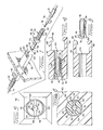
- a pair of plug members 32,33 are shown to each comprise a rearward portion 34, an intermediate portion 36, and a forward alignment nose 38.
- the plug members are composed of substantially resilient plastic material, and both of the plug members 32,33 are structurally identical.
- a series of annularly-directed, and axially-spaced gripping flanges 40 are provided integral with the rearward portion 34 of the plug member.
- a somewhat larger retention flange 42 is further provided and located between the rearward portion 34 and the intermediate portion 36 of each plug member.
- Extending annularly around the intermediate portion 36 is an alignment rib 44 which is located substantially equidistant from the ends of the intermediate portion 36.
- An axial bore extends through each of the plug members 32,33 and is comprised of a rearward bore 46, an intermediate bore 48, and a profiled opening 50 which projects through the alignment nose 38 of each plug member, and which communicates with the intermediate bore 48.
- the forward profiled opening 50 through the alignment nose 38 is defined by upper convergent surfaces 52, which converge away from the opening, and a pair of lower convergent surfaces 54 which converge downward and away from the opening.
- a transverse slot 56 is further provided to extend through the forward alignment nose 38 of each plug member, and is located so as to separate the upper convergent surfaces 52 from the lower surfaces 54.
- Situated on the external surface of the forward alignment nose 38 are a pair of upper alignment protrusions 58 and a pair of lower alignment protrusions 60.
- the protrusions 58,60 are structured to be substantially resilient and compressible for a purpose to be explained in detail below. Further, it will be noted that the upper protrusions 58 are positioned to be diametrically opposed to corresponding lower protrusions 60, with the upper and lower protrusions 58,60 being situated on opposite sides of the transverse slot 56.
- a bulkhead mounted receptacle 62 is shown, having an axial passageway 64 extending therethrough.
- a pair of cantilever fingers 66 extend outwardly and provide latching flanges 68 at the respective remote ends thereof.
- a mounting flange 70 is provided about receptacle 62 and receives a pair of mounting screws 72 therethrough to affix the receptacle to the bulkhead.
- the receptacle body 62 is preferably composed of plastics material.
- the receptacle 62 is intended optically to couple a pair of optical fibre, or waveguide, cables 74 which are structured having an interior fibre 76 and an outer jacket 78.
- the inner fibre 76 of such cables is typically composed of plastics material of optical quality, and can vary in diametric size between 16 to 40 thousandths of an inch.
- the jacket layer 78 which surrounds the interior fibre 76 functions to protect the fibre from external forces. Since the invention is intended to accommodate a termination of optical cables having a substantially wide range of dimension, operation of the connector will first be described for a fibre having an interior fibre of relatively small diametric dimension, and subsequently, and description of the operation of the subject invention will be presented for a cable having an interior fibre of relatively larger diametric dimension.
- each retention sleeve 10 comprises a plurality of annularly-spaced and outwardly-projecting tines 16 formed therefrom.
- the tines 16 project outwardly, and are biased in a rearward direction for a purpose explained below.
- each retention sleeve further constitutes a plurality of annularly-located and inwardly-projecting tines 17, which are biased to project into an axial sleeve bore 20. It will be appreciated that the precise number of projections 16,18 is not critical, and that the projections are spaced apart and formed by a stamping operation through the metallic retention sleeve, forming the projections accordingly.
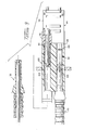
- the optical fibre cable 74 is prepared for termination by removing the jacket 78 from a forward end of the fibre 76. Thereafter, the fibre cable 74 is inserted through the tubular retention sleeve 10 and the plug member 32, as shown in Figure 2. It will be appreciated that the inwardly-directed tines 18 of the retention sleeve 10 resiliently exert engaging pressure on the jacket 78 of the cable. Subsequently, as shown in Figure 2, the retention sleeve 10 is inserted into the rearward bore 46 of the plug member 32. So located, the fibre cable 74 projects through the intermediate bore 48, and the fibre 76 projects through the profiled opening 50 of the alignment nose 38.
- the inwardly-directed tines 18 are made to penetrate into the jacket 78 of the cable, to thereby mechanically engage the cable and inhibit rearward withdrawal of the cable from the retention sleeve 10.
- This axial tension further acts to draw the outward tines 16 of the retention sleeve 10 into penetrating engagement with the plug member rearward portion 34. Consequently, the retention sleeve 10 is mechanically retained within the plug member, by operation of the outward directed tines 16.
- the fibre optic cable 74 is mechanically retained within the retention sleeve 10 by operation of the inward directed tines 18.
- the forward end of the fibre 76 projects through the profiled opening of alignment nose 38. Thereafter, by a cutting technique common within the industry, the forward end surface of the fibre 76 is severed into a coplanar relationship with the forward end surface of the plug member 32. So located, the fibre cable 74 extends forward through the intermediate portion 36 of the plug member, and a small unjacketed portion of the fibre 76 projects through the alignment nose 38 to a forward end of a plug member. As best illustrated in Figure 5, the forward unjacketed portion of the fibre 76 is loosely contained between the convergent surfaces 52 and 54 of the alignment nose 38.
- the plug member is now in a condition for insertion into the receptacle 62, as shown in Figure 2.
- the cantilever fingers 66 ride over the retention flange 42 of the plug member to mechanically lock the plug member into an engaging relationship with the receptacle.
- the protrusions 58,60 of the alignment portion 38 and the annular alignment rib 44 of the intermediate portions 36 of the plug member engage with the receptacle walls defining the passageway 64 and compress radially inward.
- the engagement between the alignment rib 44 and the receptacle sidewalls serves to axially locate the plug member on the major axis of the passageway. Further, engagement of the protrusions 58,60 of the nose portion serves to radially compress convergent surfaces 52 and 54 of the nose portion 38 about the fibre 76, as shown in Figure 6.
- the compressible protrusions 58,60 engage the receptacle and cause the surfaces 52 and 54 to wedge the optical fibre 76 therebetween.
- the transverse slot 56 accommodates radial movement of the surfaces toward the optical fibre. In wedging the fibre between surfaces 52 and 54, the fibre is thereby located on the major axis of the passageway of the receptacle.' The presence of the transverse slot 56 and the compressible nature of the protrusions 58,60 operate to render the subject connector plug relatively insensitive to optical fibre dimensional variances.
- the interior dimensions of the intermediate bore 48 are sufficiently large to accommodate receipt of optical fibre cables having an outer diameter which may vary within a specified range.
- the alignment nose 38 is structured to accommodate optical fibres having diameters variable about nominal dimensions of 16 or 40 thousands of an inch.
- the pair of plug members 32,33 are inserted into opposite ends of the passageway 64 and are brought into abutting opposition intermediate of the passageway. There located, the axes of the fibres 76 extending through the alignment nose portion of each plug member are in alignment on the major axis of the passageway 64, and an efficient optical coupling between two optical cables is thereby effectuated.
- the body of the intermediate portion 36 does not frictionally engage the receptacle, but rather, an axial gap 80 exists between the annular alignment rib 44 and the protrusions 58,60 of the plug member. This gap reduces insertion friction and enables the plug to be inserted with minimal amount of insertion force required.
- the plug member achieves an alignment function solely by operation of the rib 44 and the protrusions on the alignment nose 38 of the plug member.
- each of the subject connector plugs can accommodate receipt of an optical cable 74, the inner fibre 76 of which has a diameter which is somewhat larger than that of the fibre illustrated in the preceding discussion.
- a fibre 76 of larger outer dimension is shown to project through the alignment portion 38 of the plug member in the manner described above.
- the oversize fibre still projects freely, but with less clearance, through the opening in the nose portion of the plug member, prior to insertion of the plug member into the receptacle passageway.
- the protrusions 58,60 of the nose portion compressibly engage the receptacle sidewalls lining the passageway, to locate the optical fibre 76 on the axis passageway.
- an inward dimple 82 is created by flexed material of the plug. The dimple 82 extends annularly around the intermediate plug portion 36, and stress relieves the plug member from forces generated by the protrusions 58,60 and the alignment rib 44.
- the embodiment described above comprises a connector plug of unitary configuration which is adapted to receive an optical cable having an interior bore and outer diameter dimension variable within limits. Further, no polishing is required when effectuating such a termination; nor is there a need for adhesive material in mechanically attaching the plug to the optical cables. Furthermore, since the termination of optical cable by operation of the subject invention requires no specialized tooling, it is therefore suitable for field applications. Lastly, the optical fibre connector is comprised of inexpensive-to-produce components which result in a connector of substantially lower manufacturing cost than currently available alternatives in the industry.
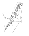
- the duplex plug 84 comprises a pair of forward projecting plug members 90,92 which are encased jointly in an elastomeric plug body 94.
- the plug body 94 is further provided with a rectangular retention flange 96 intermediate the length thereof and includes a keying projection 98 as shown.
- the keying projection 98 is located immediately forward of the retention flange 96 and along the external side of the plug member 92.
- the duplex receptacle 100 is provided with a keying slot 102 in one side thereof, and is further structured to provide a pair of parallel and adjacent axial bores 104,106 projecting therethrough. It will be appreciated that the receptacle 100 is a duplex version of the simplex receptacle 62 illustrated in Figure 1. It will further be noted upon a combined consideration of Figures 8 and 9 that the duplex receptacle 100 is adapted to alternatively receive a duplex plug 84 therein, or a pair of simplex plugs 32,33.
- the alignment structure of the duplex and simplex plugs are identical and coaxial alignment of the optical waveguides terminated by each is as previously described.
- the keying projection 98 of the duplex plug 84 is aligned within the keying slot 102 of the receptacle.
- the simplex plugs 32,33 having no such keying projection, may be readily inserted into the duplex receptacle bores at the option of the user.
- the duplex receptacle 100 can matingly couple a pair of duplex plugs 84, or four simplex plugs such as 32,33 or a single duplex plug; and a pair of simplex plugs.
- Such versatility enables the user of the subject invention to converge a pair of optical waveguides from remote locations on a printed circuit board to a single duplex receptacle, and then exit the duplex receptacle through a single duplex plug.
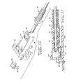
- an active device mount 108 may be used in combination with a simplex plug 32 as illustrated.
- the active device mount 108 comprises a low profile body 110 having slotted mounting flanges 112 extending therefrom at right angles for either vertical or horizontal (shown horizontal) mounting of the active device mount on a printed circuit board 126.
- a pair of parallel cantilever fingers 114 project forward of the module body 110, each having a latching flange 116 at the forward end thereof.
- the cantilever fingers 114 function similarly as the cantilever fingers 66 illustrated in Figure 2.
- the body 110 is provided with an axial bore 118 extending therein, and communicating with a larger dimensioned counterbore 120 located in a rearward portion of the body.
- the counterbore 120 is adapted to receive an electro-optic device package 122 therein, having a plurality of leads 124 exiting the mount body at right angles.
- the active device package 122 includes an emitter or detector chip (not shown) which aligns on the axis of the mount body bore 118.
- the right-angled leads 124 are intended for electrical engagement with the semiconductor chip and project opposite ends through a printed circuit board 126 to establish electrical interconnections with circuitry on the printed circuit board.
- the simplex plug 32 is matingly inserted into a forward end of the active device mount 108, and serves to colinearly align an optical waveguide on the axis of the mount bore 118, thereby establishing an optical coupling with the semiconductor chip.
- the subject plug member is provided with alignment structure which functions independently of the rotational status of the plug member.
- each plug member can be rotated 90 degrees, and inserted into the receptacle bore to effectuate alignment of the optical waveguide on the axis of the bore.
- the risk of mismating between the receptacle and each plug member is thereby reduced.
- the subject connector comprises a relatively few number of component parts, which are amenable to factory pre-assembly.
- the retention sleeve 10 may be pre-located in each plug member 32,33,58, and shipped as an integral package. Thereafter, in a field environment, the single unitary package may be applied to an optical waveguide without the use of adhesive or special tools. The absence of loose pieces in the field represents significant convenience to the user of the subject invention.
- the subject active device mount of the invention provides a relatively low profile.
- This low profile reduces the space required in affixing the active device mount to a printed circuit board, thereby presenting significant advantages in packaging.
- the simplex plug 32 is coupled to the active device mount body by a straight axial movement, and snaps into mating engagement without the use of complicated coupling mechanisms such as screw threads and nuts. Since the dimensional size of these components is relatively small and the space on the printed circuit board in which to work is comparatively limited, a straight-forward means for mating the connector components of the subject invention is a significant advantage over the prior art, and permits location of the active device mount anywhere on the printed circuit board and not only on the board edge.
Landscapes
- Physics & Mathematics (AREA)
- General Physics & Mathematics (AREA)
- Optics & Photonics (AREA)
- Mechanical Coupling Of Light Guides (AREA)
Applications Claiming Priority (6)
| Application Number | Priority Date | Filing Date | Title |
|---|---|---|---|
| US06/244,526 US4418983A (en) | 1981-03-16 | 1981-03-16 | Optical waveguide connector |
| US06/244,527 US4477146A (en) | 1981-03-16 | 1981-03-16 | Optical waveguide connector |
| US244527 | 1981-03-16 | ||
| US244526 | 1981-03-16 | ||
| US244454 | 1981-03-16 | ||
| US06/244,454 US4415232A (en) | 1981-03-16 | 1981-03-16 | Optical waveguide splice |
Related Parent Applications (1)
| Application Number | Title | Priority Date | Filing Date |
|---|---|---|---|
| EP82301066.5 Division | 1982-03-03 |
Publications (3)
| Publication Number | Publication Date |
|---|---|
| EP0154781A2 true EP0154781A2 (de) | 1985-09-18 |
| EP0154781A3 EP0154781A3 (en) | 1986-02-19 |
| EP0154781B1 EP0154781B1 (de) | 1990-07-18 |
Family
ID=27399757
Family Applications (2)
| Application Number | Title | Priority Date | Filing Date |
|---|---|---|---|
| EP85100800A Expired - Lifetime EP0154781B1 (de) | 1981-03-16 | 1982-03-03 | Verbinder für optische Wellenleiter |
| EP82301066A Expired EP0061243B1 (de) | 1981-03-16 | 1982-03-03 | Verbindung für Lichtwellenleiter |
Family Applications After (1)
| Application Number | Title | Priority Date | Filing Date |
|---|---|---|---|
| EP82301066A Expired EP0061243B1 (de) | 1981-03-16 | 1982-03-03 | Verbindung für Lichtwellenleiter |
Country Status (5)
| Country | Link |
|---|---|
| EP (2) | EP0154781B1 (de) |
| CA (1) | CA1196221A (de) |
| DE (2) | DE3280216D1 (de) |
| HK (1) | HK48389A (de) |
| SG (1) | SG16789G (de) |
Cited By (9)
| Publication number | Priority date | Publication date | Assignee | Title |
|---|---|---|---|---|
| WO1988003662A1 (fr) * | 1986-11-05 | 1988-05-19 | Albatron Elektronik Gmbh | Transformateur opto-electronique avec element de connexion pour guides d'ondes lumineuses |
| EP0257706A3 (en) * | 1986-08-22 | 1988-06-08 | Philips Patentverwaltung Gmbh | Arrangement for non-tension connection of an optical cabarrangement for non-tension connection of an optical cable with a coupling device le with a coupling device |
| EP0375168A1 (de) * | 1988-12-21 | 1990-06-27 | The Whitaker Corporation | Optischer Stecker |
| US5166995A (en) * | 1984-06-08 | 1992-11-24 | Amp Incorporated | Polarized connector |
| WO1994009397A1 (en) * | 1992-10-21 | 1994-04-28 | Minnesota Mining And Manufacturing Company | Fiber optic edge card connector |
| EP0730174A3 (de) * | 1995-02-06 | 1997-05-02 | Molex Inc | Duplex-Verbinder |
| WO2009100796A1 (de) * | 2008-02-16 | 2009-08-20 | Huber + Suhner Ag | Kabeleinführung mit vorgelagerter haltevorrichtung |
| WO2011113736A1 (de) | 2010-03-18 | 2011-09-22 | Huber+Suhner Ag | Interfaceverbinder |
| US8942532B2 (en) | 2009-07-06 | 2015-01-27 | Huber+Suhner Ag | Plug-in device for an optical cable |
Families Citing this family (12)
| Publication number | Priority date | Publication date | Assignee | Title |
|---|---|---|---|---|
| US4762389A (en) * | 1984-03-30 | 1988-08-09 | Nec Corporation | Optical fiber connector |
| JPS6188208A (ja) * | 1984-10-08 | 1986-05-06 | Nec Corp | 光フアイバ・コネクタ |
| US4725120A (en) * | 1984-10-25 | 1988-02-16 | American Telephone And Telegraph Company, At&T Bell Laboratories | Connector apparatus |
| FR2595149B1 (fr) * | 1986-02-28 | 1988-05-13 | Cit Alcatel | Dispositif d'etancheite longitudinale pour l'ame d'un cable optique |
| IT1222901B (it) * | 1987-10-14 | 1990-09-12 | Pirelli Cavi Spa | Connettore per fibre ottiche e metodo per posizionare assialmente una fibra ottica nel connettore |
| US5042891A (en) * | 1990-06-21 | 1991-08-27 | Amp Incorporated | Active device mount assembly with interface mount for push-pull coupling type optical fiber connectors |
| JPH0675142A (ja) * | 1992-08-25 | 1994-03-18 | Yamaichi Electron Co Ltd | 光コネクタ |
| DK0744035T3 (da) * | 1994-02-08 | 2000-04-03 | Miniflex Ltd | Indretning til styring af kabler |
| NL9401073A (nl) * | 1994-06-28 | 1996-02-01 | Framatome Connectors Belgium | Connectorsamenstel. |
| DE19501133C1 (de) * | 1995-01-05 | 1996-05-23 | Siemens Ag | Baugruppe mit einer elektrischen Baueinheit und Verfahren zum Fixieren einer elektrischen Baueinheit |
| DE50013282D1 (de) * | 2000-02-11 | 2006-09-14 | Huber+Suhner Ag | Optischer steckverbinder zum gleichzeitigen verbinden einer mehrzahl von faseroptischen kabeln sowie einsatz für einen solchen steckverbinder |
| JP6775783B2 (ja) * | 2017-09-21 | 2020-10-28 | 矢崎総業株式会社 | 光コネクタ装置 |
Citations (5)
| Publication number | Priority date | Publication date | Assignee | Title |
|---|---|---|---|---|
| DE1200614B (de) | 1961-02-16 | 1965-09-09 | Cable Covers Ltd | Kupplungsmuffe fuer Stangen, Kabel, Drahtseile od. dgl. |
| US3569933A (en) | 1969-07-29 | 1971-03-09 | Amp Inc | Signalling system with indicating means |
| US3637284A (en) | 1969-12-22 | 1972-01-25 | Gen Motors Corp | Male connector terminal for fiberloptic bundles |
| US4081208A (en) | 1977-01-17 | 1978-03-28 | General Motors Corporation | Optical and electrical conduit termination means for circuit board |
| EP0011561A1 (de) | 1978-11-13 | 1980-05-28 | RADIALL Société anonyme dite: | Verfahren zum Anbringen einer optischen Faser in einer Verbindungszwinge |
Family Cites Families (5)
| Publication number | Priority date | Publication date | Assignee | Title |
|---|---|---|---|---|
| US1817772A (en) * | 1927-10-27 | 1931-08-04 | Harry E Sipe | Tube and pipe coupling |
| DE2723440C3 (de) * | 1977-05-24 | 1979-11-29 | Siemens Ag, 1000 Berlin Und 8000 Muenchen | Steckverbindung für Lichtwellenleiter mit axialer und radialer Verspannung eines Gewindes |
| US4178068A (en) * | 1977-11-14 | 1979-12-11 | Amp Incorporated | Fiber optic cable termination means |
| GB2025084B (en) * | 1978-06-19 | 1982-07-07 | Elliott Brothers London Ltd | Terminating optical fibres |
| US4354731A (en) * | 1979-10-02 | 1982-10-19 | E. I. Du Pont De Nemours And Company | Self-aligning optical fiber connector |
-
1982
- 1982-02-19 CA CA000396671A patent/CA1196221A/en not_active Expired
- 1982-03-03 DE DE8585100800T patent/DE3280216D1/de not_active Expired - Fee Related
- 1982-03-03 EP EP85100800A patent/EP0154781B1/de not_active Expired - Lifetime
- 1982-03-03 DE DE8282301066T patent/DE3271608D1/de not_active Expired
- 1982-03-03 EP EP82301066A patent/EP0061243B1/de not_active Expired
-
1989
- 1989-03-29 SG SG167/89A patent/SG16789G/en unknown
- 1989-06-15 HK HK483/89A patent/HK48389A/xx unknown
Patent Citations (5)
| Publication number | Priority date | Publication date | Assignee | Title |
|---|---|---|---|---|
| DE1200614B (de) | 1961-02-16 | 1965-09-09 | Cable Covers Ltd | Kupplungsmuffe fuer Stangen, Kabel, Drahtseile od. dgl. |
| US3569933A (en) | 1969-07-29 | 1971-03-09 | Amp Inc | Signalling system with indicating means |
| US3637284A (en) | 1969-12-22 | 1972-01-25 | Gen Motors Corp | Male connector terminal for fiberloptic bundles |
| US4081208A (en) | 1977-01-17 | 1978-03-28 | General Motors Corporation | Optical and electrical conduit termination means for circuit board |
| EP0011561A1 (de) | 1978-11-13 | 1980-05-28 | RADIALL Société anonyme dite: | Verfahren zum Anbringen einer optischen Faser in einer Verbindungszwinge |
Cited By (11)
| Publication number | Priority date | Publication date | Assignee | Title |
|---|---|---|---|---|
| US5166995A (en) * | 1984-06-08 | 1992-11-24 | Amp Incorporated | Polarized connector |
| EP0257706A3 (en) * | 1986-08-22 | 1988-06-08 | Philips Patentverwaltung Gmbh | Arrangement for non-tension connection of an optical cabarrangement for non-tension connection of an optical cable with a coupling device le with a coupling device |
| WO1988003662A1 (fr) * | 1986-11-05 | 1988-05-19 | Albatron Elektronik Gmbh | Transformateur opto-electronique avec element de connexion pour guides d'ondes lumineuses |
| EP0375168A1 (de) * | 1988-12-21 | 1990-06-27 | The Whitaker Corporation | Optischer Stecker |
| WO1994009397A1 (en) * | 1992-10-21 | 1994-04-28 | Minnesota Mining And Manufacturing Company | Fiber optic edge card connector |
| EP0730174A3 (de) * | 1995-02-06 | 1997-05-02 | Molex Inc | Duplex-Verbinder |
| WO2009100796A1 (de) * | 2008-02-16 | 2009-08-20 | Huber + Suhner Ag | Kabeleinführung mit vorgelagerter haltevorrichtung |
| CN101952757B (zh) * | 2008-02-16 | 2012-12-12 | 胡贝尔和茹纳股份公司 | 具有上游安装固定件的电缆插入件 |
| US8475200B2 (en) | 2008-02-16 | 2013-07-02 | Huber + Suhner Ag | Cable insertion having upstream mounting fixture |
| US8942532B2 (en) | 2009-07-06 | 2015-01-27 | Huber+Suhner Ag | Plug-in device for an optical cable |
| WO2011113736A1 (de) | 2010-03-18 | 2011-09-22 | Huber+Suhner Ag | Interfaceverbinder |
Also Published As
| Publication number | Publication date |
|---|---|
| EP0061243B1 (de) | 1986-06-11 |
| EP0154781A3 (en) | 1986-02-19 |
| EP0154781B1 (de) | 1990-07-18 |
| CA1196221A (en) | 1985-11-05 |
| SG16789G (en) | 1989-07-07 |
| DE3280216D1 (de) | 1990-08-23 |
| DE3271608D1 (en) | 1986-07-17 |
| EP0061243A1 (de) | 1982-09-29 |
| HK48389A (en) | 1989-06-23 |
Similar Documents
| Publication | Publication Date | Title |
|---|---|---|
| US4418983A (en) | Optical waveguide connector | |
| EP0154781B1 (de) | Verbinder für optische Wellenleiter | |
| US4477146A (en) | Optical waveguide connector | |
| EP1172672B1 (de) | Staubabdeckung für faseroptischen Steckverbinder mit zwei Funktionen | |
| CA1255522A (en) | Optical fiber connector | |
| EP1073923B1 (de) | Steckergehäuse mit schnappverbindung für einen faseroptischen stecker | |
| US5553180A (en) | Adapter assembly for fiber optic connectors | |
| EP0248902B1 (de) | Verbindungsstück mit optischen fasern | |
| US5082344A (en) | Adapter assembly with improved receptacle for a push-pull coupling type of optical fiber connector | |
| EP0547778A1 (de) | Hermaphroditischer Steckverbinder für ein einadriges Glasfaserkabel | |
| EP1148366B1 (de) | Glasfaserstecker mit Exzentrizitätsanpassung | |
| EP0979430B1 (de) | Optischer faser stecker | |
| US5123071A (en) | Overconnector assembly for a pair of push-pull coupling type optical fiber connectors | |
| EP0213672A2 (de) | Vielfachfaser optischer Kabelstecker | |
| US5671310A (en) | Optical fiber connector having an adjustable engaging extent | |
| US4852963A (en) | Optical fiber biconic connector | |
| EP0685750A1 (de) | Stecker zum Verbinden eines faseroptischen Kabels | |
| JPS646441B2 (de) | ||
| CN101091131A (zh) | 可现场安装的光纤连接器 | |
| KR20020006480A (ko) | 광섬유 커넥터용 정렬 시스템 | |
| US4733934A (en) | Connector for a fiber optic cable | |
| US4798441A (en) | Fiber optic device coupling | |
| US4664464A (en) | Coaxial cable termination | |
| EP0547777A1 (de) | Einadriger hermaphorditischer Glasfasersteckverbinder | |
| US4588257A (en) | Separable splice for optic fibers |
Legal Events
| Date | Code | Title | Description |
|---|---|---|---|
| PUAI | Public reference made under article 153(3) epc to a published international application that has entered the european phase |
Free format text: ORIGINAL CODE: 0009012 |
|
| 17P | Request for examination filed |
Effective date: 19850126 |
|
| AC | Divisional application: reference to earlier application |
Ref document number: 61243 Country of ref document: EP |
|
| AK | Designated contracting states |
Designated state(s): AT BE CH DE FR GB IT LI NL SE |
|
| PUAL | Search report despatched |
Free format text: ORIGINAL CODE: 0009013 |
|
| AK | Designated contracting states |
Designated state(s): AT BE CH DE FR GB IT LI NL SE |
|
| 17Q | First examination report despatched |
Effective date: 19890113 |
|
| RAP3 | Party data changed (applicant data changed or rights of an application transferred) |
Owner name: AMP INCORPORATED (A NEW JERSEY CORPORATION) |
|
| RAP1 | Party data changed (applicant data changed or rights of an application transferred) |
Owner name: AMP INCORPORATED |
|
| GRAA | (expected) grant |
Free format text: ORIGINAL CODE: 0009210 |
|
| ITF | It: translation for a ep patent filed | ||
| AC | Divisional application: reference to earlier application |
Ref document number: 61243 Country of ref document: EP |
|
| AK | Designated contracting states |
Kind code of ref document: B1 Designated state(s): CH DE FR GB IT LI NL |
|
| REF | Corresponds to: |
Ref document number: 3280216 Country of ref document: DE Date of ref document: 19900823 |
|
| ET | Fr: translation filed | ||
| PLBE | No opposition filed within time limit |
Free format text: ORIGINAL CODE: 0009261 |
|
| STAA | Information on the status of an ep patent application or granted ep patent |
Free format text: STATUS: NO OPPOSITION FILED WITHIN TIME LIMIT |
|
| 26N | No opposition filed | ||
| PGFP | Annual fee paid to national office [announced via postgrant information from national office to epo] |
Ref country code: FR Payment date: 19930208 Year of fee payment: 12 |
|
| PGFP | Annual fee paid to national office [announced via postgrant information from national office to epo] |
Ref country code: GB Payment date: 19930217 Year of fee payment: 12 Ref country code: DE Payment date: 19930217 Year of fee payment: 12 |
|
| PGFP | Annual fee paid to national office [announced via postgrant information from national office to epo] |
Ref country code: CH Payment date: 19930302 Year of fee payment: 12 |
|
| ITTA | It: last paid annual fee | ||
| PGFP | Annual fee paid to national office [announced via postgrant information from national office to epo] |
Ref country code: NL Payment date: 19930331 Year of fee payment: 12 |
|
| PG25 | Lapsed in a contracting state [announced via postgrant information from national office to epo] |
Ref country code: GB Effective date: 19940303 |
|
| PG25 | Lapsed in a contracting state [announced via postgrant information from national office to epo] |
Ref country code: LI Effective date: 19940331 Ref country code: CH Effective date: 19940331 |
|
| REG | Reference to a national code |
Ref country code: GB Ref legal event code: 732E |
|
| PG25 | Lapsed in a contracting state [announced via postgrant information from national office to epo] |
Ref country code: NL Effective date: 19941001 |
|
| GBPC | Gb: european patent ceased through non-payment of renewal fee |
Effective date: 19940303 |
|
| NLV4 | Nl: lapsed or anulled due to non-payment of the annual fee | ||
| PG25 | Lapsed in a contracting state [announced via postgrant information from national office to epo] |
Ref country code: FR Effective date: 19941130 |
|
| REG | Reference to a national code |
Ref country code: CH Ref legal event code: PL |
|
| PG25 | Lapsed in a contracting state [announced via postgrant information from national office to epo] |
Ref country code: DE Effective date: 19941201 |
|
| REG | Reference to a national code |
Ref country code: FR Ref legal event code: ST |