EP0154748B1 - Système d'alimentation pour connecteurs - Google Patents
Système d'alimentation pour connecteurs Download PDFInfo
- Publication number
- EP0154748B1 EP0154748B1 EP84308606A EP84308606A EP0154748B1 EP 0154748 B1 EP0154748 B1 EP 0154748B1 EP 84308606 A EP84308606 A EP 84308606A EP 84308606 A EP84308606 A EP 84308606A EP 0154748 B1 EP0154748 B1 EP 0154748B1
- Authority
- EP
- European Patent Office
- Prior art keywords
- cassette
- cassettes
- housings
- connector
- stop
- Prior art date
- Legal status (The legal status is an assumption and is not a legal conclusion. Google has not performed a legal analysis and makes no representation as to the accuracy of the status listed.)
- Expired - Lifetime
Links
- 239000004020 conductor Substances 0.000 claims description 6
- 238000003780 insertion Methods 0.000 claims description 3
- 230000037431 insertion Effects 0.000 claims description 3
- 230000005484 gravity Effects 0.000 claims description 2
- 230000004888 barrier function Effects 0.000 claims 1
- 238000004519 manufacturing process Methods 0.000 description 2
- 239000000463 material Substances 0.000 description 2
- 230000003247 decreasing effect Effects 0.000 description 1
- 238000006073 displacement reaction Methods 0.000 description 1
- 238000001125 extrusion Methods 0.000 description 1
- 238000009413 insulation Methods 0.000 description 1
- 230000013011 mating Effects 0.000 description 1
- 239000002184 metal Substances 0.000 description 1
- 230000003287 optical effect Effects 0.000 description 1
- 230000002028 premature Effects 0.000 description 1
- 230000000717 retained effect Effects 0.000 description 1
Images


Classifications
-
- H—ELECTRICITY
- H01—ELECTRIC ELEMENTS
- H01R—ELECTRICALLY-CONDUCTIVE CONNECTIONS; STRUCTURAL ASSOCIATIONS OF A PLURALITY OF MUTUALLY-INSULATED ELECTRICAL CONNECTING ELEMENTS; COUPLING DEVICES; CURRENT COLLECTORS
- H01R43/00—Apparatus or processes specially adapted for manufacturing, assembling, maintaining, or repairing of line connectors or current collectors or for joining electric conductors
- H01R43/04—Apparatus or processes specially adapted for manufacturing, assembling, maintaining, or repairing of line connectors or current collectors or for joining electric conductors for forming connections by deformation, e.g. crimping tool
- H01R43/048—Crimping apparatus or processes
- H01R43/055—Crimping apparatus or processes with contact member feeding mechanism
Definitions
- This invention relates to cassettes for containing electrical connector components and to apparatus for feeding the components from cassettes.
- One type of electrical connector is assembled in stages. In an intermediate condition, terminals associated with the connector are partly inserted into the connector housing. Portions of the terminals extend from the housing and are terminated to conductors before the terminals are fully inserted into a final position within the housing.
- the connectors may be produced, shipped and stored in the intermediate assembly stage, and then must be oriented and fed to automatic or partly automatic terminating machinery. With this type of connector, problems are encountered not only due to the difficulty of orienting and feeding the connectors, but also due to the vulnerability of the exposed portions of the delicate terminals which extend from the housing in the intermediate assembly condition. Premature insertion of terminals from the intermediate to the final position must be prevented.
- connector feeding apparatus for supplying electrical connector components to automated terminating apparatus or the like comprising elongated hollow cassettes in each of which numerous components are loaded in a serial array, support means holding a plurality of the cassettes in generally parallel, side-by-side relation, means defining a component feed path aligned with and extending away from a first one of the plurality of cassettes, means for pushing the serial array of components in said first cassette from said first cassette and into said feed path, a sensor for providing a control signal when the final component of the serial array is pushed from said first cassette, and cassette advancing means responsive to said control signal for replacing said first cassette with an adjacent second cassette when said first cassette is emptied.
- the present invention is characterised in that the cassettes are piled upon one another on the support means and in that said support means includes vertically extending guide members confining said plurality of cassettes in a vertical stack and base means supporting said first cassette at the bottom of said vertical stack whereby on removal of said base means, said first cassette is replaced by said second adjacent cassette under the action of gravity.
- Figs. 1-3 illustrate a feed apparatus generally designated as 10 constructed in accordance with the present invention.
- Apparatus 10 feeds electrical connectors 12 to a point of use such as automated connector terminating equipment or the like (not shown).
- the connectors 12 are contained in cassettes, each generally designated as 14.
- the connectors 12 are of the type adapted to be partly assembled at the point of manufacture and thereafter to be terminated and finally assembled at a different location.
- Each connector 12 includes a housing 16 including several terminal receiving cavities 18 (Fig. 5) in which conductive metal terminals 20 may be inserted.
- terminals 20 are partly inserted into housing cavities 18 and portions of the terminals extend outwardly of the housing 16.
- Each terminal 20 includes a box or barrel shaped contact portion 22 located at one end of the terminal.
- a planar base section 24 joins the box contact portion 22 with a conductor contact portion 26 at the other end of the terminal.
- Contact portion 26 includes an insulation displacement section 28 and a crimp section 30 providing a strain relief function when the terminal 20 is connected to a conductor.
- a carrier strip 32 extends transversely to join the terminals 20 of each connector housing 16 for ease of handling, and is severed or broken off from the terminals 20 in conjunction with the terminating operation.
- Housing 16 includes two spaced apart stop structures in the form of apertures or recesses 34 and 36 formed along each cavity 18 in a wall of the housing.
- a stop tang 38 of each terminal 20 is engagable with aperture 34 in the illustrated intermediate assembly condition. After a conductor has been terminated to the terminal 20, the terminal is movable into the recess to a fully inserted position in which the stop tang 38 engages the aperture 36.
- An additional aperture 40 formed in housing 16 communicates with each cavity 18 so that a pin contact or other conductor can be inserted through the aperture 40 to make an electrical connection with the box contact portion 22 of the terminal 20 in its final assembly position.
- each housing includes a flexible and resilient locking tang 42 useful in mounting the finished connector in association with a mating connector, as well as one or more projecting tabs 44 which may form an indexing or guiding function.
- a number of the electrical connectors 12 are contained in a cassette 14.
- the cassette 14 is an elongated, hollow, tubular body of material having an essentially uniform cross section throughout its length. This cross section is best illustrated in Fig. 5 wherein it can be seen that the cassette includes a continuous outer wall 46 generally conforming to a substantially rectangular outline.
- a number of the cassettes 14 can be arranged side-by-side in stacks or rows.
- Cassette wall 46 defines a first region 48 for slidably receiving housings 16 of connectors 12.
- An adjacent second region 50 encloses the projecting portions of the terminals 20 when the connectors are in the illustrated, partly assembled position.
- An indented portion 46A of the wall 46 and a number of continuous, inwardly extending ribs 52, 54, 56 and 58 define a nest-like structure for capturing the housings 16 of connectors 12 in the region 48.
- the configuration of these elements of the cassette 14 permits the connectors 12 to be inserted into the cassette 14 only in the specific configuration illustrated in Fig. 5. If a connector 12 is inverted either vertically or horizontally to a different position, then the connector cannot be inserted into the cassette 14.
- connectors 12 are partly assembled to the intermediate condition illustrated in the drawings, typically by automated equipment which supplies the connectors one at a time in series in a consistent and predetermined orientation.
- a number of the connectors are loaded into one end of a cassette 14 until the cassette is substantially full of connectors in a serial, side-by-side array with the terminal cavities 18 extending transversely to the length of the cassette.
- both ends of the cassette are provided with a pin 60 (Fig. 6) frictionally and releasably retained in holes 62 formed in the cassette.
- one or both of the pins 60 is withdrawn from the holes 62.
- Cassette 14 protects the connectors 12 while they are in their intermediate assembly condition.
- the delicate projecting portions of the terminals 20 cannot be deformed or damaged.
- the terminals 20 cannot be accidentally moved from the intermediate to the final assembly position prior to termination.
- the connectors 12 When the connectors 12 have been loaded into the cassettes 14, they can be handled, shipped and stored in their oriented serial array without the necessity for reorienting the connectors at the time of termination and final assembly.
- the feed apparatus 10 dispenses electrical connectors 12 from cassettes 14 and automatically delivers the connectors to a point of use such as automated terminating equipment or the like.
- Apparatus 10 supports a number of loaded cassettes 14, feeds connectors 12 from one cassette, and automatically replaces the cassette when emptied with the next adjacent loaded cassette.
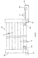
- apparatus 10 includes a pair of generally C-shaped support columns 64 and 65 bracketing or partly enclosing the ends of a vertical stack of cassettes 14 (Figs. 1 and 3).
- Principles of the invention are applicable to other arrangements; for example cassettes 14 may be arrayed in a horizontal row, or a number of vertical stacks may be arranged side-by-side.
- the stack of cassettes 14 is vertically suspended upon a pair of base members 66 and 68 engaging the underside of the lowermost cassette 14.
- the stop pins 60 Prior to stacking cassettes 14 in the feed apparatus 10, the stop pins 60 are removed from the cassettes to permit sliding movement of the connectors 12 out of the cassettes 14.
- a support member 70 located adjacent one of the columns 64 defines a feed path 72 aligned with and extending away from one end of the lowermost cassette 14 and terminating in a stop surface or abutment 74. As seen in Fig. 4, a passage 76 extends through support column 64 to permit connectors 12 to move from cassette 14 into the feed path 72.
- the other support column 65 includes a passageway 78 (Fig. 1) through which pressurized air is admitted to the opposite end of the lowermost cassette 14 to push the serial array of connectors 12 out of the cassette, through the passage 76 and along the feed path 72 against the stop surface 74.
- Connectors may be dispensed from the feed path 72 and advanced to a point of use such as automated terminating equipment.
- a pusher 80 operated by an air cylinder 82 moves connectors at right angles along a delivery path 84 away from the feed path 72.
- the serial array of connectors from the cassette 14 continues to be fed one at a time against the stop surface 74 by means of air pressure supplied through passage 78.
- the apparatus 10 When the lowermost cassette 14 is emptied of connectors 12, the apparatus 10 automatically replaces the empty cassette with the next adjacent loaded cassette.
- a sensor is provided for indicating when the lowermost cassette 14 is emptied. As illustrated in Fig. 4, the sensor may take the form of an optical device including a light source 86 and a light sensitive device 88 disposed on opposite sides of passage 76 in the support column 64. When the last connector 12 of the cassette 14 moves through the passage 76, a control signal is provided to indicate that the lowermost cassette 14 is empty.
- a pneumatic control system 90 for controlling the replacement of empty cassettes in response to a control signal indicating that the cassette in use is empty.
- the base members 66 and 68 are movable under the control of air cylinders 92 and 94 respectively.
- the control system 90 pressurizes pressure lines 96 and 98 to maintain the base members 66 and 68 in the extended position illustrated in Fig. 3.
- lines 96 and 98 are depressurized and lines 100 and 102 are pressurized so that the cylinders 92 and 94 withdraw the base members 66 and 68 to permit the emptied cassette to drop from the stack and out of the support columns 64 and 65.
- a pair of gripping elements 104 and 106 retain the second cassette 14 and the upper portion of the stack of cassettes while the base members 66 and 68 are retracted. Gripping elements 104 and 106 are controlled by air cylinders 108 and 110. Normally, the gripping elements are in their illustrated retracted positions due to pressurization of lines 112 and 114. Prior to retraction of the base members 66 and 68, the control system 90 depressurizes the lines 112 and 114 and pressurizes lines 116 and 118 to extend the gripping elements 104 and 106 tightly against the next adjacent cassette 14.
- the base members 66 and 68 are returned to their normal position by pressurization of lines 96 and 98. Thereafter, the gripping elements 104 and 106 are retracted by pressurization of lines 112 and 114 so that the stack of cassettes drops with the next loaded cassette 14 in engagement with the base members 66 and 68. At this point, the next cassette is in alignment with the passage 76 and feed path 72 so that the advancing of connectors 12 along the feed path 76 and against the stop surface 74 is continued automatically without interrupting the supply of cassettes delivered through delivery path 84.
- the control system 90 may operate to disable the air cylinder 82 and pusher 80 by pressurizing line 120 and depressurizing line 122 during the time that an empty cassette 14 is being replaced with a loaded cassette.
- the supply of pressurized air to the passage 78 in the support column 65 may be continuous. If desired, the pneumatic control 90 can interrupt the supply of pressurized air during the time that an empty cassette is removed from the bottom of the stack of cassettes.
- the cassette and feed apparatus of the present invention is especially suited for use with small electrical connectors which are difficult to handle in bulk and to orient for feeding and termination.
- the connectors 12 include terminals arranged at a contact spacing of about 0.010 inch.
- the cassette 14 is approximately 25 inches long and contains 30 connectors 12, each having eight terminal positions.
- the cassette 14 can conveniently be fabricated as an inexpensive plastic extrusion, and may be formed of transparent or translucent material so that a loaded cassette can readily be distinguished from an empty cassette.
Landscapes
- Engineering & Computer Science (AREA)
- Manufacturing & Machinery (AREA)
- Manufacturing Of Electrical Connectors (AREA)
Claims (14)
Applications Claiming Priority (2)
| Application Number | Priority Date | Filing Date | Title |
|---|---|---|---|
| US06/584,047 US4653665A (en) | 1984-02-27 | 1984-02-27 | Connector cassette and feed system |
| US584047 | 1984-02-27 |
Publications (3)
| Publication Number | Publication Date |
|---|---|
| EP0154748A2 EP0154748A2 (fr) | 1985-09-18 |
| EP0154748A3 EP0154748A3 (en) | 1987-04-22 |
| EP0154748B1 true EP0154748B1 (fr) | 1990-04-25 |
Family
ID=24335702
Family Applications (1)
| Application Number | Title | Priority Date | Filing Date |
|---|---|---|---|
| EP84308606A Expired - Lifetime EP0154748B1 (fr) | 1984-02-27 | 1984-12-11 | Système d'alimentation pour connecteurs |
Country Status (5)
| Country | Link |
|---|---|
| US (1) | US4653665A (fr) |
| EP (1) | EP0154748B1 (fr) |
| JP (1) | JPS60189883A (fr) |
| CA (1) | CA1223845A (fr) |
| DE (1) | DE3482089D1 (fr) |
Families Citing this family (10)
| Publication number | Priority date | Publication date | Assignee | Title |
|---|---|---|---|---|
| EP0190633A1 (fr) * | 1985-02-02 | 1986-08-13 | Hermann Kronseder | Dispositif chargeur d'étiquettes pour étiqueteuse et procédé pour échanger des magasins de recharge |
| US4831696A (en) * | 1988-05-06 | 1989-05-23 | American Telephone And Telegraph Company | Component insertion machine apparatus |
| US4873762A (en) * | 1988-05-06 | 1989-10-17 | American Telephone And Telegraph Company, At&T-Technologies Inc. | Component insertion machine apparatus |
| US4941795A (en) * | 1988-11-21 | 1990-07-17 | At&T Bell Laboratories | Component insertion machine apparatus |
| US5360109A (en) * | 1993-04-28 | 1994-11-01 | Molex Incorporated | Packaging tray for electrical connectors |
| DE59504912D1 (de) * | 1995-07-26 | 1999-03-04 | Stocko Metallwarenfab Henkels | Artikelzuführung |
| DE59508142D1 (de) * | 1995-11-03 | 2000-05-11 | Stocko Metallwarenfab Henkels | Verfahren und Vorrichtung zur halbautomatischen Herstellung von Leitungssätzen |
| US6547097B1 (en) * | 1999-05-27 | 2003-04-15 | The Knight Group Llc | Dispensing apparatus and method |
| US6719518B2 (en) * | 2001-10-15 | 2004-04-13 | Anadigics, Inc. | Portable tube holder apparatus |
| ITUB20150293A1 (it) | 2015-05-06 | 2016-11-06 | Delta Srl | Materiale composito autopulente per la produzione di articoli stampati per l'arredo cucina e bagno. |
Citations (1)
| Publication number | Priority date | Publication date | Assignee | Title |
|---|---|---|---|---|
| US4288023A (en) * | 1979-07-12 | 1981-09-08 | Orthodyne Electronics | Parts storage and handling system |
Family Cites Families (11)
| Publication number | Priority date | Publication date | Assignee | Title |
|---|---|---|---|---|
| US2325165A (en) * | 1942-03-12 | 1943-07-27 | American Seal Kap Corp | Remote photoelectric control |
| US2934378A (en) * | 1957-09-11 | 1960-04-26 | Arden Farms Co | Article handling method and apparatus |
| US3308977A (en) * | 1965-10-04 | 1967-03-14 | Ibm | Automatic tray handler |
| US3591041A (en) * | 1969-01-31 | 1971-07-06 | True Plastic Corp | Denesting machine |
| FR2473479A2 (fr) * | 1980-01-16 | 1981-07-17 | Guigan Jean | Dispositif pour la distribution de produits surgeles |
| FR2474270A1 (fr) * | 1980-01-21 | 1981-07-24 | Radiotechnique Compelec | Procede et dispositif d'assemblage simultane de composants sur un support |
| US4401234A (en) * | 1981-06-01 | 1983-08-30 | Universal Research Laboratories, Incorporated | Apparatus for applying integrated circuits to a circuit board |
| US4420880A (en) * | 1982-04-29 | 1983-12-20 | Western Electric Company, Inc. | Device for extracting an in-line array of socket-mounted circuit packages of the dual-in-line-type |
| US4488662A (en) * | 1982-11-18 | 1984-12-18 | At&T Technologies, Inc. | Magazining device for use with automatic component assembling machine |
| JPS5997929A (ja) * | 1982-11-26 | 1984-06-06 | Hitachi Ltd | マガジン供給装置 |
| US4500246A (en) * | 1983-03-01 | 1985-02-19 | Universal Instruments Corporation | Indexed feed of electronic component supply tubes |
-
1984
- 1984-02-27 US US06/584,047 patent/US4653665A/en not_active Expired - Lifetime
- 1984-12-05 CA CA000469351A patent/CA1223845A/fr not_active Expired
- 1984-12-11 DE DE8484308606T patent/DE3482089D1/de not_active Expired - Lifetime
- 1984-12-11 EP EP84308606A patent/EP0154748B1/fr not_active Expired - Lifetime
-
1985
- 1985-02-18 JP JP60030152A patent/JPS60189883A/ja active Granted
Patent Citations (1)
| Publication number | Priority date | Publication date | Assignee | Title |
|---|---|---|---|---|
| US4288023A (en) * | 1979-07-12 | 1981-09-08 | Orthodyne Electronics | Parts storage and handling system |
Also Published As
| Publication number | Publication date |
|---|---|
| JPH0253918B2 (fr) | 1990-11-20 |
| US4653665A (en) | 1987-03-31 |
| CA1223845A (fr) | 1987-07-07 |
| EP0154748A3 (en) | 1987-04-22 |
| EP0154748A2 (fr) | 1985-09-18 |
| JPS60189883A (ja) | 1985-09-27 |
| DE3482089D1 (de) | 1990-05-31 |
Similar Documents
| Publication | Publication Date | Title |
|---|---|---|
| EP0154748B1 (fr) | Système d'alimentation pour connecteurs | |
| US4235015A (en) | Electrical harness fabrication method and apparatus | |
| EP0137631B1 (fr) | Appareil pour produire automatiquement un câble avec cosses serties | |
| FI65871C (fi) | Anordning foer montering av elektriska anslutningsdon i kablar | |
| US4936011A (en) | Method of inserting a terminated wire lead into a connector cavity | |
| US8826522B2 (en) | Method and set of tools for inserting ferrite members onto electrical filter connectors | |
| EP0330309A2 (fr) | Appareil de fabrication de faisceaux de câbles sertis et méthode | |
| US4370806A (en) | Electrical harness fabrication apparatus | |
| US6315156B1 (en) | Tape-form packaging system and apparatus for effecting assembly and disassembly thereof | |
| EP0288248A1 (fr) | Système de retenue de contact électrique, méthode et outil pour son enlèvement | |
| US4525927A (en) | Method and apparatus for connecting an insulating housing of a connector and a cover | |
| US4680841A (en) | Electrical harness fabrication apparatus | |
| US4310967A (en) | Apparatus for electrical harness fabrication | |
| US5305879A (en) | Package for card edge connectors | |
| US4333230A (en) | Machine for making an electrical harness | |
| EP0193255B1 (fr) | Appareil pour décharger une boîte à stockage contenant une matrice de positions de stockage | |
| US4864719A (en) | Tool for removing electrical contacts | |
| US3846895A (en) | Dual-in-line package extraction tool | |
| DE3434883A1 (de) | Einsetzvorrichtung fuer elektronische bauteile | |
| EP0498394B1 (fr) | Dispositif pour guider des articles hors de magazines tubulaires | |
| US4653187A (en) | Connector fabrication method and apparatus | |
| EP0001678B1 (fr) | Appareil pour déployer des fils conducteurs | |
| EP0292297B1 (fr) | Machine à fabriquer des harnais de fil | |
| US4770591A (en) | Apparatus for unloading a container having a matrix of storage positions | |
| US4660279A (en) | Apparatus for electrical harness manufacture |
Legal Events
| Date | Code | Title | Description |
|---|---|---|---|
| PUAI | Public reference made under article 153(3) epc to a published international application that has entered the european phase |
Free format text: ORIGINAL CODE: 0009012 |
|
| AK | Designated contracting states |
Designated state(s): CH DE FR GB IT LI NL |
|
| 17P | Request for examination filed |
Effective date: 19851022 |
|
| PUAL | Search report despatched |
Free format text: ORIGINAL CODE: 0009013 |
|
| AK | Designated contracting states |
Kind code of ref document: A3 Designated state(s): CH DE FR GB IT LI NL |
|
| RIN1 | Information on inventor provided before grant (corrected) |
Inventor name: LICTUS, LEONARD J. Inventor name: ZAHLIT, WAYNE A. Inventor name: HEISNER, DOUGLAS L. |
|
| RIN1 | Information on inventor provided before grant (corrected) |
Inventor name: LICKUS, LEONARD J. Inventor name: ZAHLIT, WAYNE A. Inventor name: HEISNER, DOUGLAS L. |
|
| 17Q | First examination report despatched |
Effective date: 19881014 |
|
| GRAA | (expected) grant |
Free format text: ORIGINAL CODE: 0009210 |
|
| AK | Designated contracting states |
Kind code of ref document: B1 Designated state(s): CH DE FR GB IT LI NL |
|
| ITF | It: translation for a ep patent filed | ||
| REF | Corresponds to: |
Ref document number: 3482089 Country of ref document: DE Date of ref document: 19900531 |
|
| ET | Fr: translation filed | ||
| PLBE | No opposition filed within time limit |
Free format text: ORIGINAL CODE: 0009261 |
|
| STAA | Information on the status of an ep patent application or granted ep patent |
Free format text: STATUS: NO OPPOSITION FILED WITHIN TIME LIMIT |
|
| 26N | No opposition filed | ||
| ITTA | It: last paid annual fee | ||
| PGFP | Annual fee paid to national office [announced via postgrant information from national office to epo] |
Ref country code: NL Payment date: 20000929 Year of fee payment: 17 |
|
| PGFP | Annual fee paid to national office [announced via postgrant information from national office to epo] |
Ref country code: GB Payment date: 20001107 Year of fee payment: 17 |
|
| PGFP | Annual fee paid to national office [announced via postgrant information from national office to epo] |
Ref country code: FR Payment date: 20001204 Year of fee payment: 17 |
|
| PGFP | Annual fee paid to national office [announced via postgrant information from national office to epo] |
Ref country code: DE Payment date: 20001222 Year of fee payment: 17 |
|
| PGFP | Annual fee paid to national office [announced via postgrant information from national office to epo] |
Ref country code: CH Payment date: 20001229 Year of fee payment: 17 |
|
| PG25 | Lapsed in a contracting state [announced via postgrant information from national office to epo] |
Ref country code: GB Free format text: LAPSE BECAUSE OF NON-PAYMENT OF DUE FEES Effective date: 20011211 |
|
| PG25 | Lapsed in a contracting state [announced via postgrant information from national office to epo] |
Ref country code: LI Free format text: LAPSE BECAUSE OF NON-PAYMENT OF DUE FEES Effective date: 20011231 Ref country code: CH Free format text: LAPSE BECAUSE OF NON-PAYMENT OF DUE FEES Effective date: 20011231 |
|
| REG | Reference to a national code |
Ref country code: GB Ref legal event code: IF02 |
|
| PG25 | Lapsed in a contracting state [announced via postgrant information from national office to epo] |
Ref country code: NL Free format text: LAPSE BECAUSE OF NON-PAYMENT OF DUE FEES Effective date: 20020701 |
|
| PG25 | Lapsed in a contracting state [announced via postgrant information from national office to epo] |
Ref country code: DE Free format text: LAPSE BECAUSE OF NON-PAYMENT OF DUE FEES Effective date: 20020702 |
|
| GBPC | Gb: european patent ceased through non-payment of renewal fee |
Effective date: 20011211 |
|
| REG | Reference to a national code |
Ref country code: CH Ref legal event code: PL |
|
| PG25 | Lapsed in a contracting state [announced via postgrant information from national office to epo] |
Ref country code: FR Free format text: LAPSE BECAUSE OF NON-PAYMENT OF DUE FEES Effective date: 20020830 |
|
| NLV4 | Nl: lapsed or anulled due to non-payment of the annual fee |
Effective date: 20020701 |
|
| REG | Reference to a national code |
Ref country code: FR Ref legal event code: ST |