EP0154591A1 - Electron-gun for an electron-tube - Google Patents
Electron-gun for an electron-tube Download PDFInfo
- Publication number
- EP0154591A1 EP0154591A1 EP85400424A EP85400424A EP0154591A1 EP 0154591 A1 EP0154591 A1 EP 0154591A1 EP 85400424 A EP85400424 A EP 85400424A EP 85400424 A EP85400424 A EP 85400424A EP 0154591 A1 EP0154591 A1 EP 0154591A1
- Authority
- EP
- European Patent Office
- Prior art keywords
- cathode
- grid
- tube
- electron
- axis
- Prior art date
- Legal status (The legal status is an assumption and is not a legal conclusion. Google has not performed a legal analysis and makes no representation as to the accuracy of the status listed.)
- Granted
Links
Images

Classifications
-
- H—ELECTRICITY
- H01—ELECTRIC ELEMENTS
- H01J—ELECTRIC DISCHARGE TUBES OR DISCHARGE LAMPS
- H01J23/00—Details of transit-time tubes of the types covered by group H01J25/00
- H01J23/02—Electrodes; Magnetic control means; Screens
- H01J23/06—Electron or ion guns
- H01J23/065—Electron or ion guns producing a solid cylindrical beam
Definitions
- the present invention relates to electron guns for electronic tubes.
- the use of a zero release voltage leads both to a reduction in the distance d between the grid and the cathode, which is then of the order for example of a few hundredths of a millimeter, and an increase in absolute value of the blocking voltage.
- the force F applied to the grid during blocking of the beam is then very high.
- the resulting vibrations have the particular disadvantage of causing modulation of the beam power during the conduction stage.
- their modulation frequency covers a very wide band and it may happen that it is precisely equal to a mechanical resonance frequency of the grid.
- the amplitudes of the vibrations are then very high, which can cause short circuits between the grid and the cathode by bringing them into contact. These vibrations can also cause the destruction of the grid by exceeding the elastic limit of the material which constitutes it.
- the present invention provides a simple and effective solution to the problems stated above.
- the present invention relates to an electron gun for an electron tube, comprising in particular a cathode whose emissive surface is in the form of a spherical cap, with in the vicinity of this cathode, a grid also in the form of a spherical cap which can be subjected to two different potentials for power modulation of the electron beam emitted by the cathode, characterized in that the distance between the cathode and the modulation grid increases as one approaches the axis of the tube.
- the solution of the invention can be used regardless of the value of the release voltage, whether zero or positive, and regardless of the use of traveling wave tubes, or other tubes provided with such guns.
- the invention therefore makes it possible, while retaining the same size for the electron gun, to reduce the value of the forces which are exerted on the grid on the axis of the tube and in the vicinity of this axis, by increasing the distance between the cathode and the grid at this location.
- the grid is held by a mechanical fixing, so there is no problem of vibrations.
- the invention makes it possible to make at least ten times lower the excitation force exerted at the center of the grid when the release voltage is zero.
- Another embodiment of the invention relates to the case of electron guns, comprising in particular a cathode, with in the vicinity of this cathode, first and second grids, in the form of a spherical cap, the first grid being brought to the potential of the cathode and the second grid can be subjected to two different potentials to modulate in power the electron beam emitted by the cathode.
- the distance between these two grids increases when approaching the axis of the tube.
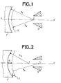
- FIG. 1 represents the diagram of an embodiment of an electron gun according to the prior art.
- La- Figure 1 is a schematic longitudinal section of this gun.
- cathode 1 On the left in the figure, cathode 1 is shown, the emissive surface is in the form of a spherical cap.
- the modulation grid 2 In the vicinity of the cathode is the modulation grid 2 which can be subjected to two different potentials to power modulate the beam.
- This grid is also in the form of a spherical cap.
- the radius of curvature R G of this grid is centered on the axis of the tube XX 'at the same point C as that where the radius of curvature RK of the cathode is centered.
- the distance between the cathode and the grid is therefore constant at all points.
- the acceleration electrode 3 is shown diagrammatically on the right of the figure.
- FIG. 2 represents the diagram of an embodiment of an electron gun according to the invention.
- the grid 2 is always in the form of a spherical cap, but the radius of curvature R G of the modulation grid 2 is centered on the axis of the tube XX 'at a point CI which is located after, if we consider the direction of movement of the electrons, the point C where the radius of curvature R K of the cathode is centered.
- the distance between the cathode 1 and the modulation grid 2 increases when one approaches the axis of the tube. This distance is greater on the axis of the tube - dimension a - than at the periphery of the tube - dimension b.
- the a / b ratio varies according to the characteristics of the gun such as the emission density, the distance between the modulation grid and the cathode, the surface convergence of the electron beam ... This ratio is substantially between 1, 5 and 3: 1.5 ⁇ a / b ⁇ 3.
- FIG. 3 is the diagram of another embodiment of a cannon according to the prior art. It is a barrel which differs from that of FIG. 1, because the cathode is followed by a first grid G 1 and a second grid G 2 , in the form of a spherical cap.
- the first grid G 1 is brought to the potential of the cathode 1. It is a grid of the "shadow grid” type. It is the second grid G 2 which can be subjected to two different potentials allowing the power modulation of the beam.
- the cathode and the two grids G 1 and G 2 have their radii of curvature centered at the same point C 2 on the axis XX '.
- the distance between the two grids G 1 and G 2 and between the cathode and the first grid G 1 is constant at all points.
- Figure 4 shows the barrel of Figure 3 modified according to the invention.
- the distance between the two grids G 1 and G 2 increases when we get closer to the axis XX 'of the tube. It suffices to compare in the figure the distance c to the distance d.
- the radius of curvature of the second grid G 2 is centered, at a point C 3 located on the axis XX 'after point C 2 where the radius of curvature of the grid G 1 is centered.
Landscapes
- Microwave Tubes (AREA)
Abstract
Dans les canons à électrons pour tubes électroniques, tels que les tubes à onde progressive, réalisant une modulation en puissance du faisceau d'électrons, la distance entre la cathode (1) et la grille de modulation (2) augmente lorsqu'on se rapproche de l'axe du tube (XX').In electron guns for electronic tubes, such as traveling wave tubes, performing power modulation of the electron beam, the distance between the cathode (1) and the modulation grid (2) increases as we get closer of the axis of the tube (XX ').
Description
La présente invention concerne les canons à électrons pour tubes électroniques.The present invention relates to electron guns for electronic tubes.
La description suivante va être faite dans le cas de canons destinés à des tubes à onde progressive, mais l'invention s'applique aussi à des canons destinés à d'autres sortes de tubes électroniques, tels que par exemple les klystrons.The following description will be made in the case of guns intended for traveling wave tubes, but the invention also applies to guns intended for other kinds of electronic tubes, such as for example klystrons.
Certaines applications des tubes à onde progressive nécessitent une modulation en puissance du faisceau d'électrons. On utilise alors une cathode dont la surface émissive est en forme de calotte sphérique, qui est suivie par une grille de modulation, également en forme de calotte sphérique, et dont la distance à la cathode est en tous points constante. Cette grille de modulation peut être successivement soumise à deux tensions :
- - une tension de blocage du faisceau, qui est négative par rapport à la cathode. Il n'y a plus émission d'électrons ;
- - une tension de déblocage du faisceau, qui est positive par rapport à la cathode.
- - a beam blocking voltage, which is negative with respect to the cathode. There is no longer any emission of electrons;
- - a beam release voltage, which is positive with respect to the cathode.
On peut par exemple utiliser une tension de blocage de - 100 V et une tension de déblocage de + 100 V.One can for example use a blocking voltage of - 100 V and a blocking voltage of + 100 V.
Le problème qui se pose dans ce mode d'utilisation est que la grille s'échauffe fortement lorsqu'elle reçoit une tension de déblocage positive, de + 100 V par exemple.The problem which arises in this mode of use is that the grid heats up strongly when it receives a positive release voltage, of + 100 V for example.
Pour résoudre ce problème d'échauffement de la grille, on utilise une tension de déblocage nulle et une tension de blocage un peu plus élevée en valeur absolue, égale par exemple à - 300 V.To solve this problem of heating of the grid, one uses a zero release voltage and a slightly higher blocking voltage in absolute value, equal for example to - 300 V.
Le problème qui se pose alors est que la grille de modulation vibre fortement sous l'effet du champ électrique.The problem which then arises is that the modulation grid vibrates strongly under the effect of the electric field.
En effet, la grille de modulation est soumise à des forces F proportionnelles au carré du champ électrique, et que l'on peut exprimer de la façon suivante :
F = k . (YZ/d2) ou k est un facteur de proportionnalité, où V est la tension de blocage ou de déblocage reçue par la grille et où d est la distance entre la cathode et la grille.Indeed, the modulation grid is subjected to forces F proportional to the square of the electric field, and which can be expressed as follows:
F = k. (Y Z / d 2 ) where k is a proportionality factor, where V is the blocking or unblocking voltage received by the grid and where d is the distance between the cathode and the grid.
L'utilisation d'une tension de déblocage nulle entraîne à la fois une diminution de la distance d entre la grille et la cathode, qui est alors de l'ordre par exemple de quelques centièmes de millimètre, et une augmentation en valeur absolue de la tension de blocage. La force F appliquée à la grille pendant le blocage du faisceau est alors très élevée. Les vibrations qui en résultent ont notamment pour inconvénient de provoquer une modulation de la puissance du faisceau pendant le palier de conduction. Dans certaines applications des tubes à onde progressive, leur fréquence de modulation couvre une très large bande et il peut arriver qu'elle soit justement égale à une fréquence de résonance mécanique de la grille. Les amplitudes des vibrations sont alors très fortes, ce qui peut provoquer des court-circuits entre la grille et la cathode en les mettant en contact. Ces vibrations peuvent provoquer aussi la destruction de la grille par dépassement de la limite élastique du matériau qui la constitue.The use of a zero release voltage leads both to a reduction in the distance d between the grid and the cathode, which is then of the order for example of a few hundredths of a millimeter, and an increase in absolute value of the blocking voltage. The force F applied to the grid during blocking of the beam is then very high. The resulting vibrations have the particular disadvantage of causing modulation of the beam power during the conduction stage. In certain applications of traveling wave tubes, their modulation frequency covers a very wide band and it may happen that it is precisely equal to a mechanical resonance frequency of the grid. The amplitudes of the vibrations are then very high, which can cause short circuits between the grid and the cathode by bringing them into contact. These vibrations can also cause the destruction of the grid by exceeding the elastic limit of the material which constitutes it.
La présente invention propose une solution simple et efficace aux problèmes énoncés précédemment.The present invention provides a simple and effective solution to the problems stated above.
La présente invention concerne un canon à électrons pour tube électronique, comportant notamment une cathode dont la surface émissive est en forme de calotte sphérique, avec au voisinage de cette cathode, une grille également en forme de calotte sphérique pouvant être soumise à deux potentiels différents pour moduler en puissance le faisceau d'électrons émis par la cathode, caractérisé en ce que la distance entre la cathode et la grille de modulation augmente lorsqu'on se rapproche de l'axe du tube.The present invention relates to an electron gun for an electron tube, comprising in particular a cathode whose emissive surface is in the form of a spherical cap, with in the vicinity of this cathode, a grid also in the form of a spherical cap which can be subjected to two different potentials for power modulation of the electron beam emitted by the cathode, characterized in that the distance between the cathode and the modulation grid increases as one approaches the axis of the tube.
On peut utiliser la solution de l'invention quelle que soit la valeur de la tension de déblocage,qu'elle soit nulle ou positive, et quelle que soit l'utilisation des tubes à onde progressive, ou des autres tubes munis de tels canons.The solution of the invention can be used regardless of the value of the release voltage, whether zero or positive, and regardless of the use of traveling wave tubes, or other tubes provided with such guns.
L'invention permet donc, tout en conservant le même encombrement pour le canon à électrons, de diminuer la valeur des forces qui s'exercent sur la grille sur l'axe du tube et au voisinage de cet axe, par augmentation de la distance entre la cathode et la grille à cet endroit. Comme à sa périphérie, la grille est maintenue par une fixation mécanique, il n'y a donc pas de problème de vibrations.The invention therefore makes it possible, while retaining the same size for the electron gun, to reduce the value of the forces which are exerted on the grid on the axis of the tube and in the vicinity of this axis, by increasing the distance between the cathode and the grid at this location. As at its periphery, the grid is held by a mechanical fixing, so there is no problem of vibrations.
L'invention permet de rendre au moins dix fois plus faible la force d'excitation s'exerçant au centre de la grille lorque la tension de déblocage est nulle.The invention makes it possible to make at least ten times lower the excitation force exerted at the center of the grid when the release voltage is zero.
L'expérience a montré que cette modification de la géométrie du canon n'entraînait pas de problème pour la focalisation du faisceau, ce qui n'était pas évident à priori.Experience has shown that this modification of the geometry of the barrel does not cause any problem for the focusing of the beam, which was not obvious a priori.
Un autre mode de réalisation de l'invention concerne le cas de canons à électrons, comportant notamment une cathode, avec au voisinage de cette cathode, une première et une deuxième grilles, en forme de calotte sphérique, la première grille étant portée au potentiel de la cathode et la deuxième grille pouvant être soumise à deux potentiels différents pour moduler en puissance le faisceau d'électrons émis par la cathode. Selon l'invention, la distance entre ces deux grilles augmente lorsqu'on se rapproche de l'axe du tube.Another embodiment of the invention relates to the case of electron guns, comprising in particular a cathode, with in the vicinity of this cathode, first and second grids, in the form of a spherical cap, the first grid being brought to the potential of the cathode and the second grid can be subjected to two different potentials to modulate in power the electron beam emitted by the cathode. According to the invention, the distance between these two grids increases when approaching the axis of the tube.
D'autres objets, caractéristiques et résultats de l'invention ressortiront de la description suivante, donnée à titre d'exemple non limitatif et illustrée par les figures annexées qui représentent :
- - les figures 1 et 3, les schémas de deux modes de réalisation de canons à électrons selon l'art antérieur ;
- - les figures 2 et 4, les schémas de deux modes de réalisation de canons à électrons selon l'invention.
- - Figures 1 and 3, diagrams of two embodiments of electron guns according to the prior art;
- - Figures 2 and 4, diagrams of two embodiments of electron guns according to the invention.
Sur les différentes figures, les mêmes repères désignent les mêmes éléments, mais, pour des raisons de clarté, les cotes et proportions de divers éléments ne sont pas respectées.In the different figures, the same references designate the same elements, but, for reasons of clarity, the dimensions and proportions of various elements are not observed.
La figure 1 représente le schéma d'un mode de réalisation d'un canon à électrons selon l'art antérieur.FIG. 1 represents the diagram of an embodiment of an electron gun according to the prior art.
Il s'agit d'un canon pour tube à onde progressive, fonctionnant avec modulation en puissance du faisceau d'électrons.It is a cannon for traveling wave tube, operating with power modulation of the electron beam.
La- figure 1 est une coupe schématique longitudinale de ce canon. A gauche sur la figure, on a représenté la cathode 1, dont la surface émissive est en forme de calotte sphérique. Au voisinage de la cathode se trouve la grille de modulation 2 qui peut être soumise à deux potentiels différents pour moduler en puissance le faisceau. Cette grille est également en forme de calotte sphérique. Le rayon de courbure RG de cette grille est centré sur l'axe du tube XX' au même point C que celui où est centré le rayon de courbure RK de la cathode. La distance entre la cathode et la grille est donc en tous points constante. Après la grille de modulation, on a représenté, schématiquement sur la droite de la figure l'électrode d'accélération 3.La- Figure 1 is a schematic longitudinal section of this gun. On the left in the figure, cathode 1 is shown, the emissive surface is in the form of a spherical cap. In the vicinity of the cathode is the
On a expliqué dans l'introduction à la description les inconvénients de cette structure, en particulier dans certaines utilisations des tubes à onde progressive et lorsque la tension de déblocage est nulle.The disadvantages of this structure have been explained in the introduction to the description, in particular in certain uses of traveling wave tubes and when the release voltage is zero.
La figure 2 représente le schéma d'un mode de réalisation d'un canon à électrons selon l'invention.FIG. 2 represents the diagram of an embodiment of an electron gun according to the invention.
Par rapport à la figure 1, on constate que la grille 2 est toujours en forme de calotte sphérique, mais-le rayon de courbure RG de la grille de modulation 2 est centré sur l'axe du tube XX' en un point CI qui est situé après, si l'on considère le sens de déplacement des électrons, le point C où est centré le rayon de courbure RK de la cathode.Compared to FIG. 1, it can be seen that the
On constate donc que la distance entre la cathode 1 et la grille de modulation 2 augmente lorsqu'on se rapproche de l'axe du tube. Cette distance est plus grande sur l'axe du tube - dimension a -qu'à la périphérie du tube - dimension b.It can therefore be seen that the distance between the cathode 1 and the
On a expliqué dans l'introduction à la description que cette modification de structure permet de résoudre les problèmes posés par les canons à électrons de l'art antérieur.It was explained in the introduction to the description that this structural modification makes it possible to solve the problems posed by the electron guns of the prior art.
Le rapport a/b varie selon les caractéristiques du canon telles que la densité d'émission, la distance entre la grille de modulation et la cathode, la convergence de surface du faisceau d'électrons... Ce rapport est sensiblement compris entre 1,5 et 3 : 1,5<a/b<3.The a / b ratio varies according to the characteristics of the gun such as the emission density, the distance between the modulation grid and the cathode, the surface convergence of the electron beam ... This ratio is substantially between 1, 5 and 3: 1.5 <a / b <3.
La figure 3 est le schéma d'un autre mode de réalisation d'un canon selon l'art antérieur. Il s'agit d'un canon qui se distingue de celui de la figure 1, car la cathode est suivie par une première grille G1 et une deuxième grille G2, en forme de calotte sphérique. La première grille G1 est portée au potentiel de la cathode 1. Il s'agit d'une grille du type "shadow grid". C'est la deuxième grille G2 qui peut être soumise à deux potentiels différents permettant la modulation en puissance du faisceau.FIG. 3 is the diagram of another embodiment of a cannon according to the prior art. It is a barrel which differs from that of FIG. 1, because the cathode is followed by a first grid G 1 and a second grid G 2 , in the form of a spherical cap. The first grid G 1 is brought to the potential of the cathode 1. It is a grid of the "shadow grid" type. It is the second grid G 2 which can be subjected to two different potentials allowing the power modulation of the beam.
Dans le cas de la figure 3, la cathode et les deux grilles G1 et G2 ont leurs rayons de courbure centrés au même point C2 sur l'axe XX'.In the case of FIG. 3, the cathode and the two grids G 1 and G 2 have their radii of curvature centered at the same point C 2 on the axis XX '.
La distance entre les deux grilles G1 et G2 et entre la cathode et la première grille G1 est en tous points constante.The distance between the two grids G 1 and G 2 and between the cathode and the first grid G 1 is constant at all points.
La figure 4 représente le canon de la figure 3 modifié selon l'invention. La distance entre les deux grilles G1 et G2 augmente lorsqu'on se rapproche de l'axe XX' du tube. Il suffit de comparer sur la figure la distance c à la distance d. Le rayon de courbure de la deuxième grille G2 est centré, en un point C3 situé sur l'axe XX' après le point C2 où est centré le rayon de courbure de la grille G1.Figure 4 shows the barrel of Figure 3 modified according to the invention. The distance between the two grids G 1 and G 2 increases when we get closer to the axis XX 'of the tube. It suffices to compare in the figure the distance c to the distance d. The radius of curvature of the second grid G 2 is centered, at a point C 3 located on the axis XX 'after point C 2 where the radius of curvature of the grid G 1 is centered.
Claims (3)
Applications Claiming Priority (2)
| Application Number | Priority Date | Filing Date | Title |
|---|---|---|---|
| FR8403640 | 1984-03-09 | ||
| FR8403640A FR2561039B1 (en) | 1984-03-09 | 1984-03-09 | ELECTRON CANON FOR ELECTRONIC TUBE |
Publications (2)
| Publication Number | Publication Date |
|---|---|
| EP0154591A1 true EP0154591A1 (en) | 1985-09-11 |
| EP0154591B1 EP0154591B1 (en) | 1988-01-27 |
Family
ID=9301858
Family Applications (1)
| Application Number | Title | Priority Date | Filing Date |
|---|---|---|---|
| EP85400424A Expired EP0154591B1 (en) | 1984-03-09 | 1985-03-05 | Electron-gun for an electron-tube |
Country Status (4)
| Country | Link |
|---|---|
| US (1) | US4798993A (en) |
| EP (1) | EP0154591B1 (en) |
| DE (1) | DE3561528D1 (en) |
| FR (1) | FR2561039B1 (en) |
Cited By (1)
| Publication number | Priority date | Publication date | Assignee | Title |
|---|---|---|---|---|
| US8375708B2 (en) | 2007-02-28 | 2013-02-19 | Emcon Technologies Germany (Augsburg) Gmbh | Static mixing element and method of producing a static mixing element |
Families Citing this family (1)
| Publication number | Priority date | Publication date | Assignee | Title |
|---|---|---|---|---|
| FR2683091A1 (en) * | 1991-10-25 | 1993-04-30 | Thomson Tubes Electroniques | IMPROVED COOLING DEVICE FOR HYPERFREQUENCY TUBE. |
Citations (5)
| Publication number | Priority date | Publication date | Assignee | Title |
|---|---|---|---|---|
| US2581243A (en) * | 1949-05-28 | 1952-01-01 | Rca Corp | Cathode of electron beam devices |
| US3377492A (en) * | 1965-08-03 | 1968-04-09 | Hughes Aircraft Co | Flood gun for storage tubes having a dome-shaped cathode and dome-shaped grid electrodes |
| US3500110A (en) * | 1967-08-23 | 1970-03-10 | Raytheon Co | Noncurrent intercepting electron beam control element |
| US3852633A (en) * | 1972-12-13 | 1974-12-03 | Varian Associates | Gridded electron gun |
| DE2609004B1 (en) * | 1975-12-29 | 1977-05-18 | English Electric Valve Co Ltd | ELECTRON BEAM GENERATOR FOR A LINEAR BEAM TUBE |
Family Cites Families (4)
| Publication number | Priority date | Publication date | Assignee | Title |
|---|---|---|---|---|
| BE530043A (en) * | 1953-07-02 | |||
| US4321505A (en) * | 1978-07-24 | 1982-03-23 | Varian Associates, Inc. | Zero-bias gridded gun |
| US4593230A (en) * | 1982-03-29 | 1986-06-03 | Litton Systems, Inc. | Dual-mode electron gun |
| US4583021A (en) * | 1983-04-18 | 1986-04-15 | Litton Systems, Inc. | Electron gun with improved cathode and shadow grid configuration |
-
1984
- 1984-03-09 FR FR8403640A patent/FR2561039B1/en not_active Expired
-
1985
- 1985-03-05 EP EP85400424A patent/EP0154591B1/en not_active Expired
- 1985-03-05 DE DE8585400424T patent/DE3561528D1/en not_active Expired
- 1985-03-06 US US06/708,691 patent/US4798993A/en not_active Expired - Fee Related
Patent Citations (5)
| Publication number | Priority date | Publication date | Assignee | Title |
|---|---|---|---|---|
| US2581243A (en) * | 1949-05-28 | 1952-01-01 | Rca Corp | Cathode of electron beam devices |
| US3377492A (en) * | 1965-08-03 | 1968-04-09 | Hughes Aircraft Co | Flood gun for storage tubes having a dome-shaped cathode and dome-shaped grid electrodes |
| US3500110A (en) * | 1967-08-23 | 1970-03-10 | Raytheon Co | Noncurrent intercepting electron beam control element |
| US3852633A (en) * | 1972-12-13 | 1974-12-03 | Varian Associates | Gridded electron gun |
| DE2609004B1 (en) * | 1975-12-29 | 1977-05-18 | English Electric Valve Co Ltd | ELECTRON BEAM GENERATOR FOR A LINEAR BEAM TUBE |
Non-Patent Citations (1)
| Title |
|---|
| A. LEBLOND: "Les tubes hyperfréquences", vol. II, 1972, pages 179-182, Masson & Cie, Paris, FR. * |
Cited By (1)
| Publication number | Priority date | Publication date | Assignee | Title |
|---|---|---|---|---|
| US8375708B2 (en) | 2007-02-28 | 2013-02-19 | Emcon Technologies Germany (Augsburg) Gmbh | Static mixing element and method of producing a static mixing element |
Also Published As
| Publication number | Publication date |
|---|---|
| FR2561039B1 (en) | 1987-04-03 |
| EP0154591B1 (en) | 1988-01-27 |
| FR2561039A1 (en) | 1985-09-13 |
| DE3561528D1 (en) | 1988-03-03 |
| US4798993A (en) | 1989-01-17 |
Similar Documents
| Publication | Publication Date | Title |
|---|---|---|
| EP0248689A1 (en) | Multiple-beam klystron | |
| EP0602983B1 (en) | Hybrid photomultiplier tube with high sensitivity | |
| FR2737041A1 (en) | ELECTRON GUN WITH COLD FIELD EMISSION CATHODE | |
| EP0154591B1 (en) | Electron-gun for an electron-tube | |
| US4503388A (en) | Acousto-optic signal detection system | |
| FR2685156A1 (en) | Electroacoustic transducer, and acoustic enclosure including at least one such transducer | |
| EP2472555A1 (en) | Device for the generation of hyperfrequency waves, comprising a plurality of magnetrons | |
| FR2573575A1 (en) | CATHODE RAY TUBE HAVING ION TRAP | |
| EP2936537B1 (en) | Microwave generator with oscillating virtual cathode and open reflectors | |
| FR2659492A1 (en) | HIGH FREQUENCY AMPLIFIER APPARATUS. | |
| EP0124395A1 (en) | Electron gun for microwave generators | |
| US3289122A (en) | Bombardment-free microwave waveguide window | |
| US20080265769A1 (en) | Large area hybrid photomultiplier tube | |
| US3441786A (en) | Camera tube having a variable resolving aperture | |
| FR2486712A1 (en) | MICRO-CHANNEL IMAGE INTENSIFIER TUBE, AND SHOOTING ASSEMBLY COMPRISING SUCH A TUBE | |
| HK29288A (en) | Cathode-ray tube | |
| FR2645676A1 (en) | CATHODE HAVING IMPROVED SECONDARY TRANSMISSION SURFACE AND CROSS-FIELD AMPLIFIER CONTAINING SUCH A CATHODE | |
| US3244890A (en) | Photosensitive broadband coupler using wave guide | |
| GB941734A (en) | Improvements in electron gun | |
| KR950703786A (en) | Electronic energy spectrometer | |
| FR2999796A1 (en) | ELECTRONIC OPTICAL DEVICE | |
| US4211953A (en) | Electron beam device with variable beam energy | |
| SU785903A1 (en) | Electron gun | |
| EP0308560A1 (en) | Charged-particle gun for the pulsed emission of particles having a fixed energy | |
| Evrard | Catadioptric electron optics using a retarding electrostatic field and its application to the development of short image tubes of very high performance |
Legal Events
| Date | Code | Title | Description |
|---|---|---|---|
| PUAI | Public reference made under article 153(3) epc to a published international application that has entered the european phase |
Free format text: ORIGINAL CODE: 0009012 |
|
| AK | Designated contracting states |
Designated state(s): DE GB IT |
|
| 17P | Request for examination filed |
Effective date: 19851228 |
|
| 17Q | First examination report despatched |
Effective date: 19860807 |
|
| GRAA | (expected) grant |
Free format text: ORIGINAL CODE: 0009210 |
|
| AK | Designated contracting states |
Kind code of ref document: B1 Designated state(s): DE GB IT |
|
| ITF | It: translation for a ep patent filed | ||
| REF | Corresponds to: |
Ref document number: 3561528 Country of ref document: DE Date of ref document: 19880303 |
|
| GBT | Gb: translation of ep patent filed (gb section 77(6)(a)/1977) | ||
| PLBE | No opposition filed within time limit |
Free format text: ORIGINAL CODE: 0009261 |
|
| STAA | Information on the status of an ep patent application or granted ep patent |
Free format text: STATUS: NO OPPOSITION FILED WITHIN TIME LIMIT |
|
| 26N | No opposition filed | ||
| PGFP | Annual fee paid to national office [announced via postgrant information from national office to epo] |
Ref country code: GB Payment date: 19910222 Year of fee payment: 7 |
|
| PGFP | Annual fee paid to national office [announced via postgrant information from national office to epo] |
Ref country code: DE Payment date: 19910225 Year of fee payment: 7 |
|
| ITTA | It: last paid annual fee | ||
| PG25 | Lapsed in a contracting state [announced via postgrant information from national office to epo] |
Ref country code: GB Effective date: 19920305 |
|
| GBPC | Gb: european patent ceased through non-payment of renewal fee | ||
| PG25 | Lapsed in a contracting state [announced via postgrant information from national office to epo] |
Ref country code: DE Effective date: 19921201 |