EP0154591A1 - Elektronenstrahlerzeuger für eine Elektronenröhre - Google Patents
Elektronenstrahlerzeuger für eine Elektronenröhre Download PDFInfo
- Publication number
- EP0154591A1 EP0154591A1 EP85400424A EP85400424A EP0154591A1 EP 0154591 A1 EP0154591 A1 EP 0154591A1 EP 85400424 A EP85400424 A EP 85400424A EP 85400424 A EP85400424 A EP 85400424A EP 0154591 A1 EP0154591 A1 EP 0154591A1
- Authority
- EP
- European Patent Office
- Prior art keywords
- cathode
- grid
- tube
- electron
- axis
- Prior art date
- Legal status (The legal status is an assumption and is not a legal conclusion. Google has not performed a legal analysis and makes no representation as to the accuracy of the status listed.)
- Granted
Links
Images

Classifications
-
- H—ELECTRICITY
- H01—ELECTRIC ELEMENTS
- H01J—ELECTRIC DISCHARGE TUBES OR DISCHARGE LAMPS
- H01J23/00—Details of transit-time tubes of the types covered by group H01J25/00
- H01J23/02—Electrodes; Magnetic control means; Screens
- H01J23/06—Electron or ion guns
- H01J23/065—Electron or ion guns producing a solid cylindrical beam
Definitions
- the present invention relates to electron guns for electronic tubes.
- the use of a zero release voltage leads both to a reduction in the distance d between the grid and the cathode, which is then of the order for example of a few hundredths of a millimeter, and an increase in absolute value of the blocking voltage.
- the force F applied to the grid during blocking of the beam is then very high.
- the resulting vibrations have the particular disadvantage of causing modulation of the beam power during the conduction stage.
- their modulation frequency covers a very wide band and it may happen that it is precisely equal to a mechanical resonance frequency of the grid.
- the amplitudes of the vibrations are then very high, which can cause short circuits between the grid and the cathode by bringing them into contact. These vibrations can also cause the destruction of the grid by exceeding the elastic limit of the material which constitutes it.
- the present invention provides a simple and effective solution to the problems stated above.
- the present invention relates to an electron gun for an electron tube, comprising in particular a cathode whose emissive surface is in the form of a spherical cap, with in the vicinity of this cathode, a grid also in the form of a spherical cap which can be subjected to two different potentials for power modulation of the electron beam emitted by the cathode, characterized in that the distance between the cathode and the modulation grid increases as one approaches the axis of the tube.
- the solution of the invention can be used regardless of the value of the release voltage, whether zero or positive, and regardless of the use of traveling wave tubes, or other tubes provided with such guns.
- the invention therefore makes it possible, while retaining the same size for the electron gun, to reduce the value of the forces which are exerted on the grid on the axis of the tube and in the vicinity of this axis, by increasing the distance between the cathode and the grid at this location.
- the grid is held by a mechanical fixing, so there is no problem of vibrations.
- the invention makes it possible to make at least ten times lower the excitation force exerted at the center of the grid when the release voltage is zero.
- Another embodiment of the invention relates to the case of electron guns, comprising in particular a cathode, with in the vicinity of this cathode, first and second grids, in the form of a spherical cap, the first grid being brought to the potential of the cathode and the second grid can be subjected to two different potentials to modulate in power the electron beam emitted by the cathode.
- the distance between these two grids increases when approaching the axis of the tube.
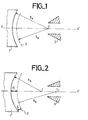
- FIG. 1 represents the diagram of an embodiment of an electron gun according to the prior art.
- La- Figure 1 is a schematic longitudinal section of this gun.
- cathode 1 On the left in the figure, cathode 1 is shown, the emissive surface is in the form of a spherical cap.
- the modulation grid 2 In the vicinity of the cathode is the modulation grid 2 which can be subjected to two different potentials to power modulate the beam.
- This grid is also in the form of a spherical cap.
- the radius of curvature R G of this grid is centered on the axis of the tube XX 'at the same point C as that where the radius of curvature RK of the cathode is centered.
- the distance between the cathode and the grid is therefore constant at all points.
- the acceleration electrode 3 is shown diagrammatically on the right of the figure.
- FIG. 2 represents the diagram of an embodiment of an electron gun according to the invention.
- the grid 2 is always in the form of a spherical cap, but the radius of curvature R G of the modulation grid 2 is centered on the axis of the tube XX 'at a point CI which is located after, if we consider the direction of movement of the electrons, the point C where the radius of curvature R K of the cathode is centered.
- the distance between the cathode 1 and the modulation grid 2 increases when one approaches the axis of the tube. This distance is greater on the axis of the tube - dimension a - than at the periphery of the tube - dimension b.
- the a / b ratio varies according to the characteristics of the gun such as the emission density, the distance between the modulation grid and the cathode, the surface convergence of the electron beam ... This ratio is substantially between 1, 5 and 3: 1.5 ⁇ a / b ⁇ 3.
- FIG. 3 is the diagram of another embodiment of a cannon according to the prior art. It is a barrel which differs from that of FIG. 1, because the cathode is followed by a first grid G 1 and a second grid G 2 , in the form of a spherical cap.
- the first grid G 1 is brought to the potential of the cathode 1. It is a grid of the "shadow grid” type. It is the second grid G 2 which can be subjected to two different potentials allowing the power modulation of the beam.
- the cathode and the two grids G 1 and G 2 have their radii of curvature centered at the same point C 2 on the axis XX '.
- the distance between the two grids G 1 and G 2 and between the cathode and the first grid G 1 is constant at all points.
- Figure 4 shows the barrel of Figure 3 modified according to the invention.
- the distance between the two grids G 1 and G 2 increases when we get closer to the axis XX 'of the tube. It suffices to compare in the figure the distance c to the distance d.
- the radius of curvature of the second grid G 2 is centered, at a point C 3 located on the axis XX 'after point C 2 where the radius of curvature of the grid G 1 is centered.
Landscapes
- Microwave Tubes (AREA)
Applications Claiming Priority (2)
| Application Number | Priority Date | Filing Date | Title |
|---|---|---|---|
| FR8403640A FR2561039B1 (fr) | 1984-03-09 | 1984-03-09 | Canon a electrons pour tube electronique |
| FR8403640 | 1984-03-09 |
Publications (2)
| Publication Number | Publication Date |
|---|---|
| EP0154591A1 true EP0154591A1 (de) | 1985-09-11 |
| EP0154591B1 EP0154591B1 (de) | 1988-01-27 |
Family
ID=9301858
Family Applications (1)
| Application Number | Title | Priority Date | Filing Date |
|---|---|---|---|
| EP85400424A Expired EP0154591B1 (de) | 1984-03-09 | 1985-03-05 | Elektronenstrahlerzeuger für eine Elektronenröhre |
Country Status (4)
| Country | Link |
|---|---|
| US (1) | US4798993A (de) |
| EP (1) | EP0154591B1 (de) |
| DE (1) | DE3561528D1 (de) |
| FR (1) | FR2561039B1 (de) |
Cited By (1)
| Publication number | Priority date | Publication date | Assignee | Title |
|---|---|---|---|---|
| US8375708B2 (en) | 2007-02-28 | 2013-02-19 | Emcon Technologies Germany (Augsburg) Gmbh | Static mixing element and method of producing a static mixing element |
Families Citing this family (1)
| Publication number | Priority date | Publication date | Assignee | Title |
|---|---|---|---|---|
| FR2683091A1 (fr) * | 1991-10-25 | 1993-04-30 | Thomson Tubes Electroniques | Dispositif de refroidissement ameliore pour tube hyperfrequence. |
Citations (5)
| Publication number | Priority date | Publication date | Assignee | Title |
|---|---|---|---|---|
| US2581243A (en) * | 1949-05-28 | 1952-01-01 | Rca Corp | Cathode of electron beam devices |
| US3377492A (en) * | 1965-08-03 | 1968-04-09 | Hughes Aircraft Co | Flood gun for storage tubes having a dome-shaped cathode and dome-shaped grid electrodes |
| US3500110A (en) * | 1967-08-23 | 1970-03-10 | Raytheon Co | Noncurrent intercepting electron beam control element |
| US3852633A (en) * | 1972-12-13 | 1974-12-03 | Varian Associates | Gridded electron gun |
| DE2609004B1 (de) * | 1975-12-29 | 1977-05-18 | English Electric Valve Co Ltd | Elektronenstrahlerzeuger fuer eine linearstrahlroehre |
Family Cites Families (4)
| Publication number | Priority date | Publication date | Assignee | Title |
|---|---|---|---|---|
| BE530043A (de) * | 1953-07-02 | |||
| US4321505A (en) * | 1978-07-24 | 1982-03-23 | Varian Associates, Inc. | Zero-bias gridded gun |
| US4593230A (en) * | 1982-03-29 | 1986-06-03 | Litton Systems, Inc. | Dual-mode electron gun |
| US4583021A (en) * | 1983-04-18 | 1986-04-15 | Litton Systems, Inc. | Electron gun with improved cathode and shadow grid configuration |
-
1984
- 1984-03-09 FR FR8403640A patent/FR2561039B1/fr not_active Expired
-
1985
- 1985-03-05 EP EP85400424A patent/EP0154591B1/de not_active Expired
- 1985-03-05 DE DE8585400424T patent/DE3561528D1/de not_active Expired
- 1985-03-06 US US06/708,691 patent/US4798993A/en not_active Expired - Fee Related
Patent Citations (5)
| Publication number | Priority date | Publication date | Assignee | Title |
|---|---|---|---|---|
| US2581243A (en) * | 1949-05-28 | 1952-01-01 | Rca Corp | Cathode of electron beam devices |
| US3377492A (en) * | 1965-08-03 | 1968-04-09 | Hughes Aircraft Co | Flood gun for storage tubes having a dome-shaped cathode and dome-shaped grid electrodes |
| US3500110A (en) * | 1967-08-23 | 1970-03-10 | Raytheon Co | Noncurrent intercepting electron beam control element |
| US3852633A (en) * | 1972-12-13 | 1974-12-03 | Varian Associates | Gridded electron gun |
| DE2609004B1 (de) * | 1975-12-29 | 1977-05-18 | English Electric Valve Co Ltd | Elektronenstrahlerzeuger fuer eine linearstrahlroehre |
Non-Patent Citations (1)
| Title |
|---|
| A. LEBLOND: "Les tubes hyperfréquences", vol. II, 1972, pages 179-182, Masson & Cie, Paris, FR. * |
Cited By (1)
| Publication number | Priority date | Publication date | Assignee | Title |
|---|---|---|---|---|
| US8375708B2 (en) | 2007-02-28 | 2013-02-19 | Emcon Technologies Germany (Augsburg) Gmbh | Static mixing element and method of producing a static mixing element |
Also Published As
| Publication number | Publication date |
|---|---|
| EP0154591B1 (de) | 1988-01-27 |
| US4798993A (en) | 1989-01-17 |
| FR2561039B1 (fr) | 1987-04-03 |
| DE3561528D1 (en) | 1988-03-03 |
| FR2561039A1 (fr) | 1985-09-13 |
Similar Documents
| Publication | Publication Date | Title |
|---|---|---|
| EP0248689A1 (de) | Mehrstrahlklystron | |
| US5374826A (en) | Hybrid photomultiplier tube with high sensitivity | |
| FR2737041A1 (fr) | Canon a electrons pourvu d'une cathode froide a emission de champ | |
| EP0154591B1 (de) | Elektronenstrahlerzeuger für eine Elektronenröhre | |
| US4503388A (en) | Acousto-optic signal detection system | |
| FR2685156A1 (fr) | Transducteur electroacoustique, et enceinte acoustique comportant au moins un tel transducteur. | |
| EP2472555A1 (de) | Vorrichtung zum Erzeugen von Hyperfrequenzwellen, die eine Vielzahl von Magnetrons umfasst | |
| FR2573575A1 (fr) | Tube a rayons cathodiques presentant un piege a ions | |
| EP2936537B1 (de) | Mikrowellengenerator mit oszillierender virtueller kathode und offenen reflektoren | |
| KR910007801B1 (ko) | 음극선관 | |
| EP0124395A1 (de) | Elektronenstrahlerzeuger für Mikrowellengeneratoren | |
| US3289122A (en) | Bombardment-free microwave waveguide window | |
| US20080265769A1 (en) | Large area hybrid photomultiplier tube | |
| HK29288A (en) | Cathode-ray tube | |
| FR2538948A1 (fr) | Tube a rayons x a balayage | |
| US3244890A (en) | Photosensitive broadband coupler using wave guide | |
| GB941734A (en) | Improvements in electron gun | |
| KR950703786A (ko) | 전자 에너지 분광계 | |
| FR2999796A1 (fr) | Dispositif d'optique electronique | |
| EP0081839A2 (de) | Elektronenstrahl-Fokussierungslinse | |
| US4211953A (en) | Electron beam device with variable beam energy | |
| SU785903A1 (ru) | Электронна пушка | |
| EP0308560A1 (de) | Geladene Teilchenkanone, welche die pulsierte Emission von Teilchen mit einer gewissen Energie erlaubt | |
| RU1772839C (ru) | Электронно-лучева лампа-политрон | |
| SU978233A1 (ru) | Электронно-лучевой прибор |
Legal Events
| Date | Code | Title | Description |
|---|---|---|---|
| PUAI | Public reference made under article 153(3) epc to a published international application that has entered the european phase |
Free format text: ORIGINAL CODE: 0009012 |
|
| AK | Designated contracting states |
Designated state(s): DE GB IT |
|
| 17P | Request for examination filed |
Effective date: 19851228 |
|
| 17Q | First examination report despatched |
Effective date: 19860807 |
|
| GRAA | (expected) grant |
Free format text: ORIGINAL CODE: 0009210 |
|
| AK | Designated contracting states |
Kind code of ref document: B1 Designated state(s): DE GB IT |
|
| ITF | It: translation for a ep patent filed | ||
| REF | Corresponds to: |
Ref document number: 3561528 Country of ref document: DE Date of ref document: 19880303 |
|
| GBT | Gb: translation of ep patent filed (gb section 77(6)(a)/1977) | ||
| PLBE | No opposition filed within time limit |
Free format text: ORIGINAL CODE: 0009261 |
|
| STAA | Information on the status of an ep patent application or granted ep patent |
Free format text: STATUS: NO OPPOSITION FILED WITHIN TIME LIMIT |
|
| 26N | No opposition filed | ||
| PGFP | Annual fee paid to national office [announced via postgrant information from national office to epo] |
Ref country code: GB Payment date: 19910222 Year of fee payment: 7 |
|
| PGFP | Annual fee paid to national office [announced via postgrant information from national office to epo] |
Ref country code: DE Payment date: 19910225 Year of fee payment: 7 |
|
| ITTA | It: last paid annual fee | ||
| PG25 | Lapsed in a contracting state [announced via postgrant information from national office to epo] |
Ref country code: GB Effective date: 19920305 |
|
| GBPC | Gb: european patent ceased through non-payment of renewal fee | ||
| PG25 | Lapsed in a contracting state [announced via postgrant information from national office to epo] |
Ref country code: DE Effective date: 19921201 |