EP0154558A2 - Auseinandernehmbarer Behälter - Google Patents
Auseinandernehmbarer Behälter Download PDFInfo
- Publication number
- EP0154558A2 EP0154558A2 EP85301581A EP85301581A EP0154558A2 EP 0154558 A2 EP0154558 A2 EP 0154558A2 EP 85301581 A EP85301581 A EP 85301581A EP 85301581 A EP85301581 A EP 85301581A EP 0154558 A2 EP0154558 A2 EP 0154558A2
- Authority
- EP
- European Patent Office
- Prior art keywords
- side wall
- elements
- connecting means
- edge
- lug
- Prior art date
- Legal status (The legal status is an assumption and is not a legal conclusion. Google has not performed a legal analysis and makes no representation as to the accuracy of the status listed.)
- Withdrawn
Links
Images


Classifications
-
- B—PERFORMING OPERATIONS; TRANSPORTING
- B65—CONVEYING; PACKING; STORING; HANDLING THIN OR FILAMENTARY MATERIAL
- B65D—CONTAINERS FOR STORAGE OR TRANSPORT OF ARTICLES OR MATERIALS, e.g. BAGS, BARRELS, BOTTLES, BOXES, CANS, CARTONS, CRATES, DRUMS, JARS, TANKS, HOPPERS, FORWARDING CONTAINERS; ACCESSORIES, CLOSURES, OR FITTINGS THEREFOR; PACKAGING ELEMENTS; PACKAGES
- B65D11/00—Containers having bodies formed by interconnecting or uniting two or more rigid, or substantially rigid, components made wholly or mainly of plastics material
- B65D11/18—Containers having bodies formed by interconnecting or uniting two or more rigid, or substantially rigid, components made wholly or mainly of plastics material collapsible, i.e. with walls hinged together or detachably connected
- B65D11/1866—Containers having bodies formed by interconnecting or uniting two or more rigid, or substantially rigid, components made wholly or mainly of plastics material collapsible, i.e. with walls hinged together or detachably connected with detachable components
- B65D11/1873—Containers having bodies formed by interconnecting or uniting two or more rigid, or substantially rigid, components made wholly or mainly of plastics material collapsible, i.e. with walls hinged together or detachably connected with detachable components all walls are detached from each other to collapse the container
Definitions
- This invention relates to containers of the kind having a base and a plurality of upstanding side walls. It will be convenient to describe the invention with particular reference to a four-sided container, but it is to be understood that the invention is not limited to such an arrangement.
- Demountable containers have the advantage of convenient storage either prior to initial use or during periods of temporary non-use. They also have advantage in situations where the supplier of goods requires return of the container in which the goods were shipped. There are many applications for such containers, but those used prior to the present invention have not been entirely satisfactory because of their complex construction, expense, or failure to provide sufficient resistance to collapse under conditions of use.
- a container according to the invention can be constructed from any of a variety of materials including paper board, but it will be convenient to particularly describe one form of the container which is manufactured from a plastics material.
- the container is characterized in that each side wall is provided with connecting means which interacts with another side wall to resist collapse of the assembled container.
- the connecting means of each side wall includes an alternating series of two types of integral components and each series is cooperable with a corresponding series of another side wall in a fashion such that each adjacent pair of cooperating components resists separation of the two walls in different directions. That is, each pair is primarily responsible for resisting separation in a direction different to that for which an adjacent pair has primary responsibility.
- a demountable container including, a plurality of side walls, connecting means provided along each of two opposite side edges of each said side wall, each said connecting means being cooperable with a said connecting means of another said side wall which is arranged angularly relative to the wall having the first said connecting means so as to releasably secure the two said walls in edge to edge relationship, each said connecting means includes a series of alternating first and second elements which extends along the respective said side wall edge, said first and second elements of each said series being relatively arranged so that the first elements of each of two cooperating said connecting means engage with respective said second elements of the other said cooperating connecting means, and the arrangement is such that the engaging first and second elements of two cooperating said connecting means function to resist separation of the respective said side walls in each of two directions which extend angularly relative to one another and transverse to the said side edges connected by the said elements.
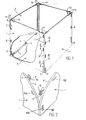
- each side wall 1 has an inwardly directed ledge 2 provided along or adjacent to its lower edge. That ledge 2 provides a support for an edge portion of the container base 3 and locating means may be provided to resist lateral separation of the base 3 and each such wall 1. As shown, that locating means may include a series of laterally spaced lugs 4 provided along each ledge 2 and each lug 4 is arranged upstanding from the respective ledge 2 so as to be locatable within a corresponding aperture 5 provided in an edge portion of the base 3. If desired, each lug 4 may be snap engagable within the respective aperture 5 so as to add to the security of the connection.
- the foregoing arrangement can be varied by providing the lugs 4 on the base 3 and the apertures within the side wall ledges 2.
- the lugs 4 and apertures 5 cooperate in the most effective manner when the side walls 1 are arranged upstanding relative to the base 3 so that the upright edges 1 of each wall 1 lie adjacent and substantially parallel to respective edges 6 of the two other walls 1. Connecting means as previously referred to enables interconnection of each pair of adjacent edges 6 so that the container becomes self supporting and has resistance to collapse.
- each side wall 1 has two series A and B of connecting components provided along respective opposite side edges 6.
- Each series A and B includes a plurality of male and female components 7 and 8 arranged in alternating sequence.
- Each female component 8 of the construction shown comprises an aperture 8 formed through the respective edge 6 and each male component 7 comprises a lug which projects laterally from the respective edge 6.
- the apertures 8 and lugs 7 are arranaged at spaced intervals along the side wall edge 6 and each aperture 8 of one series A or B is laterally aligned with a lug 7 of the other series B or A respectively of the same side wall 1 (see figure 1). That out of phase relationship between the two series A and B permits interaction of two side walls 1 as described below.
- the lugs 7 of each of teh two adjacent edges 6 are aligned with the apertures 8 of the other adjacent edge 6 (see figure 2).
- the two sets of lugs 7 however, extend in different directions (at right angles to one another) because of the relative disposition of their respective side walls 1. Assuming each side wall 1 has some degree of flexibility it is nevertheless possible to interconnect the two side walls 1 through the two series of connecting means as shown diagramatically by figure 2.
- connection operation may conveniently commence at the bottom of the two side walls 1 as shown by figure 2 and invovles locating the lowermost lug 7B of the two series A and B i nthe adjacent aperture 8A of the other side wall 1.
- the lug 7A immediately above that aperture 8A can then be located in the adjacent aperture 8B which is immediately above the aforementioned lowermost lug 7B, and that operation is repeated until all lugs 7 penetrate into or through an associated aperture 8. Since the lugs 7 of the two side walls 1 project in different directions, at least one wall 1 needs to be flexed to some extent during the connecting process. That difference in direction however, contributes to the security of the connection because a force applied to a side wall 1 in a direction such as to encourage separation of one lug 7A from its aperture 8B will not have the same affect on each of the two adjacent lugs 7B.
- inter-connection of the two side walls 1 at their edges 6 involves alternate penetration of part of one side wall 1 into the other and each such penetration step is effected in a direction different to that adopted for the immediately preceding step. That may be likened to a stitching operation. The same benefits might be obtained however, if the change in direction of penetration ocurs with less frequency so that two or more adjacent lugs 7 of the connected edges 6 extend in the same general direction.
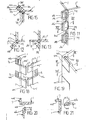
- FIGS 3 to 5 show a variation of the construction shown by figures 1 and 2 and in that variation each aperture 8 is in the form of a slot extending generally parallel to the adjacent side edge 6 of the respective side wall 1 and each lug 7 is of corresponding cross sectional shape.
- a locking lip 9 projects beyond both the upper and lower edges 10 and 11 of each lug 7 so as to snap behind a surface or step 12 (figure 4) of the other side wall 1 when the lug 7 is projected into or through an aperture 8 of that side wall 1.
- One or more slots may be formed in the lug 7 between the upper and lower edges 10 and 11 so as to increase the flexibility of the lug 7.
- each lug 7 is preferably formed integral with their respective side walls 1 as shown, but the major advantages of the invention can be achieved if separately formed lugs are used. That is, in an arrangement not shown, each lug may be in the form of a pin or the like which is connected to both side walls during the fastening operation. If desired, such a pin may be loosely captured on the side wall not having the aperture with which the pin is to be associated. Alternatively, the pins of each side wall edge may be interconnected through a strap-like member rather than existing as discrete components, and that strap-like member may be attached in an appropriate manner to the side wall or be completely separable therefrom.
- each such flange may extend at substantially 45° to the general plane of its respective side wall and is arranged to adopt face to face engagement with the corresponding flange of an adjacent side_ wall.
- the lugs and apertures may be located substantially at the junction between each such flange and the main body of the respective side wall.
- a connecting member 13 may be provided at the upper end of the adjacent edges 6 of each pair of connected side walls 1 as shown in figure 1 so as to add to the security of the side edge connection.
- Such a member 13 may be of plate-like form and arranged to snap engage with an upper edge portion of each of the two side walls 1 so as to bridge the vertical separation line between those walls 1.
- Lugs 14 on the side walls 1 may engage within respective apertures 15 of the connecting member 13, or alternatively the lugs 14 and apertures 15 may be provided on the connecting member 13 and walls 1 respectively.
- the connecting member 13 may be formed as an integral part of one side wall 1 in which event a single lug 14 and aperture 15 connection with the other side wall 1 may be sufficient.
- Such an integral member 13 may be in the form of a flap which is hingedly connected at 16 to its respective side wall 1 so as to be movable into and out of a position at which it overlies a part 17 of the upper edge 18 of an adjacent side wall 1. It may be an advantage to recess that upper edge part 17 as shown so that the connecting member 13 lies substantially flush with the uper edges 18 of the side walls 1 when in its operative position (figure 22). Also, neat location of the member 13 within such a recess could improve the rigidity of the assembled container.
- each lug 7 may be of hooked-type configuration so as to have a slot 19 which locates over a part 20 of the other side wall 1 when the two adjacent walls 1 are connected together. That is, each lug 7 is passed through an aperture 8 of the other side wall 1 and the two walls 1 are then moved vertical relative to one another to locate the wall parts 20 within respective slots 19.
- each connecting-lug 7 - may have a locking lip 9 along side edges thereof as shown in figure 2 instead of at the upper and lower edges 10 and 11 as shown by figure 5.
- each lug 7 may have a locking lip 9 along one side edge only and the corresponding aperture 8 may have adequate width to allow passage of the enlarged front edge of the lug 7 without interference, or without substantial interference.
- each side wall 1 has a rib or outwardly stepped portion 21 at a location rearwardly of the lug 7.
- the rib or stepped portion 21 projects in a direction opposite to that of the locking lip 9 and is locatable beneath a laterally projecting part 22 of the other side wall 1 as shown by figure 9.
- Such location occurs as the lug 7 is projected through the aperture 8 of the other side wall 1 and the resulting confinement of the rib or stepped portion 21 resists withdrawal of the lug 7 from its fully inserted position at which the locking lip 9 has snapped behind the side wall 1 having the aperture 8.
- the locking lip 9 may lie against or near a step 23 in the last mentioned side wall 1 when fully inserted so as to be protected against inadvertant deflection from its operative position.
- each lug 7 is positively locked against dislodgement by forces acting in a lateral direction relative to either side wall 1.
- the lugs 7 may be arranged to project from a recessed part 24 of the respective wall side edge 9 as shown for example in figure 5.
- the side edge 6 will have a plurality of recessed parts 24 which are spaced apart by an apertured portion 25 of the side wall 1, and a lug 7 will be disposed in each such recessed part 24.
- the resulting construction will therefore have a relatively neat appearance.
- each side edge connecting aperture 8 is provided in a section 26 of the respective side wall 1 which is adapted to be projected through an opening 27 in the other side wall 1.
- the cooperable lug 7 is therefore on a section 28 of its respective side wall 1 which is located outward of the opening 27 and is preferably arranged to extend laterally from that section 28.
- Either or both of the side wall sections 26 and 28 can be hingedly connected to the main body of its respective side wall 1 so that, when the apertured section 26 is projected through the opening 27 as shown in figure 13, one or both of the sections 26 and 28 can be turned towards the other to permit location of the lug 7 within the aperture 8 (figure 12).
- the hinge connection 29 of any such section 26 or 28 can be an integral part of the respective side wall 1 as shown.
- the apertured and lug bearing sections 26 and 28 are in the form of flaps which are disposed in face to face engagement when the lug 7 and aperture 8 cooperate (figures 11 and 12).
- each pair of engaging sections 26 and 28 may be directly beside another such pair.
- apertured and lug bearing sections 26 and 28 may be arranged in alternate fashion along a side edge 6 of a side wall 1, or each side edge 6 may have one form only of such sections.
- the cooperating flaps 31 and 32 may be arranged for face to face engagement without the need for one to pass through an opening in the other side wall 1.
- the apertured flap 31 extends laterally outwards from the side edge 6 of its respective side wall 1 without a hinge connection between it and that side edge 6. It is preferred that the apertured flap 31 is arranged to extend at an angle to the general plane of its respective side wall 1 as shown, and although any suitable angle could be selected an angle of substantially 45° is generally preferred.
- the lug bearing flap 32 may or may not be hingedly connected to its respective side wall 1, but is nevertheless arranged to bear against the apertured flap 31 in face to face relationship with the lug 7 protruding through the aperture 8 as shown in figure 15.
- the lug 7 is of a length such that it can penetrate through the apertured flap 31 and beyond the back surface 33 thereof, which is the surface remote from that engaging the lug bearing flap 32.
- a retaining flap 34 is hingedly connected to the outer edge 35 of the lug bearing flap 32 so that it can be turned over the outer edge 36 of the apertured flap 31 to bear against the back surface 33 of that flap 31 as shown in figure 13.
- that retaining flap 34 has an opening 37 which receives the part 38 of the lug 7 which projects beyond the back surface 33.
- the edge 39 of the retaining flap 34 remote from its hinge connection 40 may snap within a recess or opening 41 provided at or adjacent the junction between the apertured flap 31 and its respective side wall 1.
- all hinge connections can be integral parts of the respective side walls 1.
- Figures 16 and 17 show a variation of the foregoing arrangement in which the lug 7 has a lateral projection 42 at its outer end and the aperture 8 is of a size such as to allow passage of chat enlarged outer end 42.
- a locking recess is formed between the lateral projection 42 and the flap 32 bearing the lug 7, and a portion of the apertured flap 31 is received in that recess in the operative condition of the connecting means as shown by figures 16 and 17.
- the retaining flap 34 then functions to prevent removal of the apertured flap 31 from the locking recess.
- a tongue and groove connection provides a basic connection between to adjacent side walls 1 and the connecting means serves to retain the tongue and groove in cooperation.
- the groove is a continuous groove 43 formed in one side of an edge portion of one side wall 1
- the tongue 44 is an edge portion of the other side wall 1 which is neatly receivable within that groove 43.
- Any form of connecting means may be adopted in such an arrangement, but the following is a preferred form.
- a plurality of flaps 45 are hingedly attached to the side edge 6 of each of the two side walls 1.
- Each flap 45 carries a locking lug 7 which is cooperable with an aperture or recess 8 in the other side wall 1. That is, when the two side walls 1 are arranged with the tongue 44 and groove 43 engaging (figure 19), each flap 45 can be turned against an adjacent surface of the other side wall 1 so that its lug 7 cooperatively engages in the aperture or recess 8 of that other side wall 1. Such an arrangement provides resistance to separation of the tongue 44 and groove 43.
- each lug 7 may be a rib-like projection formed on a surface of the respective flap 45 and extending generally in the direction of the side edge 6 of the respective side wall.
- the corresponding aperture or recess 8 may be a groove of appropriate dimensions.
- the aperture or recess 8 could be provided on the flap 45 and the cooperating lug 7 on the other side wall 1.
- each flap 45 may locate within a correspondingly shaped recess or cavity 46 as shown provided in the surface of the other wall 1 so as to minimize inadvertant deflection from its operative position.
- FIGS 22 and 23 show still another embodiment involving hinged flaps in which each flap 47 is arranged transverse to its respective side wall 1 in much the same manner as the previously described connecting member 13 on the upper edge 18 of the side walls 1.
- Each flap 47 therefore extends laterally outwards from a surface 48 of its respective side wall 1 and is adapted to penetrate into an opening 49 provided in the other side wall 1.
- a lug and aperture type connection as previously described is provided between the flap 47 and that other side wall 1.
- the lug 7 is formed on the lower side of the opening 49 and the aperture 8 is formed through the flap 47.
- the opening 49 is of a size sufficient to allow the flap 47 to be movable within the opening 49 to permit engagement with and separation from the lug 7.
- a plurality of flaps 47 may be provided in spaced relationship along the edge portion 6 of each side wall 1. that is, each of two adjacent side wall edges 6 may have an alternating series of flaps 47 and openings 49.
- figure 24 shows two side walls 1 interconnected by a bridging piece 50 so as to produce a wall of double the normal length.
- FIG 24 and 25 show the bridging piece 50 applied to walls 1 of the general kind described in connection with figures 1 to 5.
- the bridging piece 50 has a series of openings 51, each of which receives a respective lug 7, and a series of lugs 52 each of which is receivable in a respective aperture 8.
- Such openings 51 and lugs 52 are arranged in alternating fashion along each of two longitudinal sides 53 of the bridging piece 50.
- the bridging piece 50 therefore cooperates with the connecting means of the two side walls 1 in the manner previously described but is so arranged as to retain the two walls 1 in the same general plane.
- a container according to the invention is convenient to assemble and dismantle, and the side walls are interconnected in a fashion such as to provide substantial resistance to collapse under conditions of use.
Applications Claiming Priority (2)
| Application Number | Priority Date | Filing Date | Title |
|---|---|---|---|
| AU3948/84 | 1984-03-07 | ||
| AU394884 | 1984-03-07 |
Publications (2)
| Publication Number | Publication Date |
|---|---|
| EP0154558A2 true EP0154558A2 (de) | 1985-09-11 |
| EP0154558A3 EP0154558A3 (de) | 1987-08-26 |
Family
ID=3694424
Family Applications (1)
| Application Number | Title | Priority Date | Filing Date |
|---|---|---|---|
| EP85301581A Withdrawn EP0154558A3 (de) | 1984-03-07 | 1985-03-07 | Auseinandernehmbarer Behälter |
Country Status (1)
| Country | Link |
|---|---|
| EP (1) | EP0154558A3 (de) |
Cited By (15)
| Publication number | Priority date | Publication date | Assignee | Title |
|---|---|---|---|---|
| GB2213798A (en) * | 1988-01-15 | 1989-08-23 | James Lawrence Dixon | Collapsible containers |
| DE4112725A1 (de) * | 1991-04-18 | 1992-10-22 | Bosch Siemens Hausgeraete | Verpackung |
| WO1993010981A1 (en) * | 1991-11-29 | 1993-06-10 | Solution Concepts Pty. Ltd. | Binder storage device |
| EP0569978A2 (de) * | 1992-05-15 | 1993-11-18 | Hartmut Dr. Eichmüller | Wiederverwendbarer Behälter insbesondere für Transport- und Lagerzwecke zum Schutz von (Industrie-)Gütern |
| NL9301157A (nl) * | 1993-03-11 | 1994-10-03 | Rene Matthijs Wansdronk | Door middel van nokken en gaten verbindbaar panelensamenstel. |
| WO1995005979A1 (de) * | 1993-08-26 | 1995-03-02 | Maschinenbau Und Plastverarbeitung Gmbh | Verpackungsbehälter zum transport auf paletten |
| GB2362433A (en) * | 1999-11-08 | 2001-11-21 | Nitto Kohki Co | Electromagnetic diaphragm pump |
| WO2002026573A2 (de) * | 2000-09-29 | 2002-04-04 | Storopack Hans Reichenecker Gmbh + Co. | Transport- oder lagerbox |
| US6382935B1 (en) | 1999-11-08 | 2002-05-07 | Nitto Kohki Co., Ltd | Electromagnetic diaphragm pump |
| WO2011141587A1 (es) * | 2010-05-11 | 2011-11-17 | Obeikan Mdf España, S.L. | Envase apilable |
| WO2012020151A1 (es) * | 2010-08-13 | 2012-02-16 | Obeikan Mdf España, S.L. | Envase |
| EP2910484A1 (de) | 2014-02-24 | 2015-08-26 | Jose Zamar Campos | Verschluss zur demontierbaren Montage laminarer Elemente |
| CN105705420A (zh) * | 2013-09-04 | 2016-06-22 | 奥贝坎Mdf西班牙有限公司 | 用于连接板条箱的部分的设备和方法 |
| US20170058926A1 (en) * | 2014-03-18 | 2017-03-02 | Masahiro Takubo | Assemblable structure |
| EP3578725A4 (de) * | 2017-03-27 | 2020-04-08 | Qingdao Centaury Design Co. Ltd | Anordnung für konstruktionshaus und schranksystem |
Citations (2)
| Publication number | Priority date | Publication date | Assignee | Title |
|---|---|---|---|---|
| AT133975B (de) * | 1931-09-06 | 1933-06-26 | Karl Kolomaznik | Endkantenverbindung plattenförmiger Körper. |
| DE8234952U1 (de) * | 1982-06-09 | 1983-04-07 | Slovenijales Tovarna meril Slovenj Gradec n.sol.o. Tozd Plastika n.sol.o. Pameče, Slovenj Gradec | Zusammenklappbarer Aufbewahrungs-Transportbehaelter |
-
1985
- 1985-03-07 EP EP85301581A patent/EP0154558A3/de not_active Withdrawn
Patent Citations (2)
| Publication number | Priority date | Publication date | Assignee | Title |
|---|---|---|---|---|
| AT133975B (de) * | 1931-09-06 | 1933-06-26 | Karl Kolomaznik | Endkantenverbindung plattenförmiger Körper. |
| DE8234952U1 (de) * | 1982-06-09 | 1983-04-07 | Slovenijales Tovarna meril Slovenj Gradec n.sol.o. Tozd Plastika n.sol.o. Pameče, Slovenj Gradec | Zusammenklappbarer Aufbewahrungs-Transportbehaelter |
Cited By (22)
| Publication number | Priority date | Publication date | Assignee | Title |
|---|---|---|---|---|
| GB2213798A (en) * | 1988-01-15 | 1989-08-23 | James Lawrence Dixon | Collapsible containers |
| GB2213798B (en) * | 1988-01-15 | 1991-09-25 | James Lawrence Dixon | Improvements in or relating to containers |
| DE4112725A1 (de) * | 1991-04-18 | 1992-10-22 | Bosch Siemens Hausgeraete | Verpackung |
| WO1993010981A1 (en) * | 1991-11-29 | 1993-06-10 | Solution Concepts Pty. Ltd. | Binder storage device |
| EP0569978A2 (de) * | 1992-05-15 | 1993-11-18 | Hartmut Dr. Eichmüller | Wiederverwendbarer Behälter insbesondere für Transport- und Lagerzwecke zum Schutz von (Industrie-)Gütern |
| EP0569978A3 (en) * | 1992-05-15 | 1994-06-01 | Eichmueller Hartmut | Reusable container for protection of industrial products, in particular for transport and storage |
| NL9301157A (nl) * | 1993-03-11 | 1994-10-03 | Rene Matthijs Wansdronk | Door middel van nokken en gaten verbindbaar panelensamenstel. |
| WO1995005979A1 (de) * | 1993-08-26 | 1995-03-02 | Maschinenbau Und Plastverarbeitung Gmbh | Verpackungsbehälter zum transport auf paletten |
| US6382935B1 (en) | 1999-11-08 | 2002-05-07 | Nitto Kohki Co., Ltd | Electromagnetic diaphragm pump |
| GB2362433A (en) * | 1999-11-08 | 2001-11-21 | Nitto Kohki Co | Electromagnetic diaphragm pump |
| GB2362433B (en) * | 1999-11-08 | 2004-03-31 | Nitto Kohki Co | Electromagnetic diaphragm pump |
| WO2002026573A3 (de) * | 2000-09-29 | 2002-07-25 | Reichenecker Hans Storopack | Transport- oder lagerbox |
| WO2002026573A2 (de) * | 2000-09-29 | 2002-04-04 | Storopack Hans Reichenecker Gmbh + Co. | Transport- oder lagerbox |
| US9434507B2 (en) | 2010-05-11 | 2016-09-06 | Obeikan Mdf Espana, S.L. | Stackable container |
| WO2011141587A1 (es) * | 2010-05-11 | 2011-11-17 | Obeikan Mdf España, S.L. | Envase apilable |
| WO2012020151A1 (es) * | 2010-08-13 | 2012-02-16 | Obeikan Mdf España, S.L. | Envase |
| EP3042859A4 (de) * | 2013-09-04 | 2016-09-21 | Obeikan Mdf España S L | Vorrichtung und verfahren zur verbindung von teilen von kisten |
| CN105705420A (zh) * | 2013-09-04 | 2016-06-22 | 奥贝坎Mdf西班牙有限公司 | 用于连接板条箱的部分的设备和方法 |
| CN105705420B (zh) * | 2013-09-04 | 2018-10-19 | 奥贝坎Mdf西班牙有限公司 | 用于连接板条箱的部分的设备和方法 |
| EP2910484A1 (de) | 2014-02-24 | 2015-08-26 | Jose Zamar Campos | Verschluss zur demontierbaren Montage laminarer Elemente |
| US20170058926A1 (en) * | 2014-03-18 | 2017-03-02 | Masahiro Takubo | Assemblable structure |
| EP3578725A4 (de) * | 2017-03-27 | 2020-04-08 | Qingdao Centaury Design Co. Ltd | Anordnung für konstruktionshaus und schranksystem |
Also Published As
| Publication number | Publication date |
|---|---|
| EP0154558A3 (de) | 1987-08-26 |
Similar Documents
| Publication | Publication Date | Title |
|---|---|---|
| EP0154558A2 (de) | Auseinandernehmbarer Behälter | |
| US5360263A (en) | Modular self-locking panel | |
| US3918781A (en) | Juxtaposable and superposable furniture pieces | |
| US4005795A (en) | Collapsible container | |
| EP0759400B1 (de) | Zusammenklappbarer Behälter | |
| US3973692A (en) | Injection molded folding box | |
| US6446414B1 (en) | Modular panel construction system | |
| US4285436A (en) | Integral locking tab for storage racks | |
| US4887874A (en) | Knockdown drawers and bins | |
| US4565465A (en) | Connectors for corrugated materials | |
| MY120548A (en) | Carton with panel locking means. | |
| WO1997016353A1 (en) | Collapsible container | |
| US6007170A (en) | Knock-down vertical file | |
| US20010050518A1 (en) | Knock-down vertical file | |
| US3858745A (en) | Box wall fasteners | |
| EP0953327A3 (de) | Befestigungsmittel um gegenüberliegende vordere und hintere Seitenteile eines absorbierenden Artikels zusammenzufügen | |
| US4524902A (en) | Carton handle | |
| EP0705714A2 (de) | Modulares System zum Ordnen und Lagern | |
| US4909398A (en) | Magazine file system | |
| US4749083A (en) | Bulb carton and blank therefor | |
| JPH01259806A (ja) | 段積み可能な引き出しボックス | |
| GB2101879A (en) | Improvements in or relating to a drawer | |
| GB2133830A (en) | Lockable latches | |
| US4884710A (en) | Housing for a chip card reader | |
| US4600329A (en) | Folder for paper sheets or the like |
Legal Events
| Date | Code | Title | Description |
|---|---|---|---|
| PUAI | Public reference made under article 153(3) epc to a published international application that has entered the european phase |
Free format text: ORIGINAL CODE: 0009012 |
|
| AK | Designated contracting states |
Designated state(s): AT BE CH DE FR GB IT LI LU NL SE |
|
| PUAL | Search report despatched |
Free format text: ORIGINAL CODE: 0009013 |
|
| AK | Designated contracting states |
Kind code of ref document: A3 Designated state(s): AT BE CH DE FR GB IT LI LU NL SE |
|
| STAA | Information on the status of an ep patent application or granted ep patent |
Free format text: STATUS: THE APPLICATION IS DEEMED TO BE WITHDRAWN |
|
| 18D | Application deemed to be withdrawn |
Effective date: 19880229 |
|
| RIN1 | Information on inventor provided before grant (corrected) |
Inventor name: BAYLY, PETER KINGSLEY |