EP0154268B1 - Fluid-filled power unit mount device - Google Patents
Fluid-filled power unit mount device Download PDFInfo
- Publication number
- EP0154268B1 EP0154268B1 EP85101977A EP85101977A EP0154268B1 EP 0154268 B1 EP0154268 B1 EP 0154268B1 EP 85101977 A EP85101977 A EP 85101977A EP 85101977 A EP85101977 A EP 85101977A EP 0154268 B1 EP0154268 B1 EP 0154268B1
- Authority
- EP
- European Patent Office
- Prior art keywords
- fluid
- power unit
- mount device
- partition plate
- movable
- Prior art date
- Legal status (The legal status is an assumption and is not a legal conclusion. Google has not performed a legal analysis and makes no representation as to the accuracy of the status listed.)
- Expired
Links
- 239000012530 fluid Substances 0.000 title claims description 119
- 238000005192 partition Methods 0.000 claims description 101
- 230000007246 mechanism Effects 0.000 claims description 49
- 239000002657 fibrous material Substances 0.000 claims description 4
- 238000013016 damping Methods 0.000 description 28
- 230000000694 effects Effects 0.000 description 21
- 229920001971 elastomer Polymers 0.000 description 21
- 230000002093 peripheral effect Effects 0.000 description 10
- 239000013536 elastomeric material Substances 0.000 description 6
- 230000006866 deterioration Effects 0.000 description 5
- 238000002485 combustion reaction Methods 0.000 description 4
- 230000002301 combined effect Effects 0.000 description 3
- 239000013013 elastic material Substances 0.000 description 3
- 238000004073 vulcanization Methods 0.000 description 3
- 230000009471 action Effects 0.000 description 2
- 230000005540 biological transmission Effects 0.000 description 2
- 230000008859 change Effects 0.000 description 2
- 239000000806 elastomer Substances 0.000 description 2
- 230000003068 static effect Effects 0.000 description 2
- 230000003247 decreasing effect Effects 0.000 description 1
- 238000006073 displacement reaction Methods 0.000 description 1
- 230000005489 elastic deformation Effects 0.000 description 1
- 230000001747 exhibiting effect Effects 0.000 description 1
- 238000002474 experimental method Methods 0.000 description 1
- 239000007788 liquid Substances 0.000 description 1
- 230000000630 rising effect Effects 0.000 description 1
- 239000007787 solid Substances 0.000 description 1
- XLYOFNOQVPJJNP-UHFFFAOYSA-N water Substances O XLYOFNOQVPJJNP-UHFFFAOYSA-N 0.000 description 1
Images


Classifications
-
- F—MECHANICAL ENGINEERING; LIGHTING; HEATING; WEAPONS; BLASTING
- F16—ENGINEERING ELEMENTS AND UNITS; GENERAL MEASURES FOR PRODUCING AND MAINTAINING EFFECTIVE FUNCTIONING OF MACHINES OR INSTALLATIONS; THERMAL INSULATION IN GENERAL
- F16F—SPRINGS; SHOCK-ABSORBERS; MEANS FOR DAMPING VIBRATION
- F16F13/00—Units comprising springs of the non-fluid type as well as vibration-dampers, shock-absorbers, or fluid springs
- F16F13/04—Units comprising springs of the non-fluid type as well as vibration-dampers, shock-absorbers, or fluid springs comprising both a plastics spring and a damper, e.g. a friction damper
- F16F13/06—Units comprising springs of the non-fluid type as well as vibration-dampers, shock-absorbers, or fluid springs comprising both a plastics spring and a damper, e.g. a friction damper the damper being a fluid damper, e.g. the plastics spring not forming a part of the wall of the fluid chamber of the damper
- F16F13/08—Units comprising springs of the non-fluid type as well as vibration-dampers, shock-absorbers, or fluid springs comprising both a plastics spring and a damper, e.g. a friction damper the damper being a fluid damper, e.g. the plastics spring not forming a part of the wall of the fluid chamber of the damper the plastics spring forming at least a part of the wall of the fluid chamber of the damper
- F16F13/10—Units comprising springs of the non-fluid type as well as vibration-dampers, shock-absorbers, or fluid springs comprising both a plastics spring and a damper, e.g. a friction damper the damper being a fluid damper, e.g. the plastics spring not forming a part of the wall of the fluid chamber of the damper the plastics spring forming at least a part of the wall of the fluid chamber of the damper the wall being at least in part formed by a flexible membrane or the like
Definitions
- This invention relates to a fluid-filled power unit mount device according to the preamble part of claim 1, which elastically support a power unit on a vehicle body, and more particularly to the power unit mount devices provided with a device intended to exhibit greater vibration damping effect throughout whole power unit operating ranges.
- Power unit mount devices filled with a fluid have been used extensively for elastically supporting a power unit such as an automotive internal combustion engine on a vehicle body.
- a variety of types of fluid-filled power unit mount devices have been proposed including one which is provided with a movable partition plate structure which is so located as to divide a cavity of a mount rubber into fluid and auxiliary chambers both filled with a fluid.
- the partition plate structure is formed with an orifice through which the fluid and auxiliary chambers are fluidly communicable with each other.
- vibration damping effect is obtained to large amplitude vibration in a lower frequency range (about 5-13 Hz) by virtue of resonance vibration of the fluid mass within the orifice, and to small amplitude vibration in a high frequency range (for example, 100-170 Hz) in which booming noise is generated by virtue of the vibration of the partition plate structure.
- the partition plate structure cannot move under vibration in a frequency range (for example, 250-300 Hz) slightly higher than the booming noise generating frequency range, thus considerably raising the dynamic spring constant of the power unit mount device as a whole. This allows high frequency fine vibration due to combustion in the power unit to be transmitted from the power unit to the vehicle body.
- a fluid-filled power unit mount device according to the preamble part of claim 1 is known from EP-A-40 290.
- the known device comprises an elastic block in the form of a spring element, which is securely interposed between the power unit and a vehicle body and is formed therein with a cavity.
- a diaphragm is connected to the elastic block and a partition plate consisting of two stop plates is connected to said elastic block defining a fluid chamber in said elastic block cavity.
- an auxiliary chamber is defined between partition plates and the diaphragm, said fluid and auxiliary chambers being filled with a fluid and being located on opposite sides of said partition plates.
- the partition plates comprise means defining a plurality of orifices in the form of holes and a nozzle which are formed in said partition plates to establish a fluid communication between said fluid chamber and said auxiliary chamber.
- said partition plates define a space located therebetween into which a movable elastomeric disk is inserted. This disc is mounted in said space between said partition plates such that it is freely movable in the axial direction.
- the vibration damping effect to lodge amplitude vibration is obtained by a displacement of the liquid volume contained in the nozzle since the disk is prevented from removement by means of two stop plates.
- small amplitute vibration damping effect in which booming noises are generated is obtained by virtue of movements of said disc.
- the partition plate structure formed by the two stop plates and the interposed movable disc cannot move under vibration in a frequency (for example 250 to 300 Hz) slightly higher than the booming noise generating frequency range, thus considerably raising the dynamic constant of the power unit mount device as a whole. This allows high frequency fine vibration due to combustion in the power unit to be transmitted from the power unit to the vehicle body.
- an object underlying the present invention to provide a fluid-filled power unit mount device which is able to offer a good vibration damping effect, even in a damping effect deterioration region in which vibration slightly higher in frequency than the small amplitude high frequency vibration is applied.
- a vibration damping effect can be obtained to the large amplitude low frequency vibration causing engine shake by virtue of the orifice, while the small amplitude high frequency vibration causing booming noise by virtue of the movable mechanisms which function to maintain the dynamic spring constant of the power unit mount device as a whole within a certain low range.
- the conventional power unit mount device includes a mount rubber 53 which is securely interposed between a base plate 51 on a power unit side and a base plate 52 on a vehicle body side.
- the mount rubber 53 is formed therein with an inner space 53a filled with a fluid.
- a diaphragm 54 and a partition plate structure 55 is fixedly connected to the base plate 52 thereby to define an auxiliary chamber 56 between the partition plate structure 55 and the diaphragm 54.
- the partition plate structure 55 defines a fluid chamber 57 between it and the base plate 51.
- the partition plate structure 55 includes a valve or movable mechanism 58 which is movable under large amplitude high frequency vibration and restrained from its movement under large amplitude low frequency vibration.
- the valve mechanism 58 has a movable plate 59 which is formed with an orifice 60 through which the fluid chamber 57 and the auxiliary chamber 56 are communicated with each other.
- Such a conventional power unit mount device is configurated to function as follows: To relatively large amplitude vibration in a low frequency range, damping force can be obtained upon resonance in which the fluid within the orifice serves as a mass; and to relatively small amplitude vibration in a high frequency range, damping can be accomplished by suppressing the value of dynamic spring constant of whole the power unit mount device at a predetermined range upon movement of the movable member 59 of the valve mechanism 58.
- the engine mount device is such set that engine shake generated at resonance frequency (for example, of 5-13 Hz) is prevented by providing the orifice 60 with high damping force, and booming noise is prevented from its generation by the valve mechanism 58 which makes its resonance at a frequency slightly higher than levels of 100-170 Hz at which the booming noise is generated.
- resonance frequency for example, of 5-13 Hz
- the valve mechanism 58 cannot smoothly function at a higher frequency range (for example, of 250-300 Hz) higher than the range of 100-170 Hz because of exceeding the resonance point of the valve mechanism 58, thereby providing a damping effect deterioration region in which the value of dynamic spring constant of whole the engine mount device considerably rises.
- the thus rising dynamic spring constant causes high frequency fine vibration due to combustion in an engine to be readily transmitted from the engine to a vehicle body.
- valve mechanism 58 constitutes a spring system whose resonance frequency f o is expressed by the following equation where, m * is the equivalent mass of the fluid, and K is the sum of the rigidities of the diaphragm and the mount rubber.
- the equivalent mass m * is expressed by the following equation: where, A, is the cross-sectional area of the inner space of the mount rubber; A 2 is the effective area of the valve mechanism; and m o is the mass of the fluid moving around the valve mechanism under fine vibration.
- the power unit mount device comprises an elastomeric block or mount rubber 3 is securely interposed between a base plate 1 on a power unit side and a base plate 2 on a vehicle body side.
- the mount rubber 3 is formed therein with an inner space or cavity 3a.
- a diaphragm 4 and a partition plate 6 are securely connected to the base plate 1.
- a diaphragm 5 and a partition plate 7 are securely connected to the base plate 2.
- a first auxiliary chamber 8 is defined between the diaphragm 4 and the partition plate 6.
- a second auxiliary chamber 9 is defined between the diaphragm 5 and the partition plate 7.
- the mount rubber 3 is securely connected or bonded at its upper section to the partition plate 6 and at its lower section to a generally annular support plate 10 by means of adhesion due to vulcanization.
- the partition plate 6 is bent inside at its outer peripheral section and secured onto the base plate 1, in which the outer peripheral section of the diaphragm 4 is securely put between the partition plate 6 and the base plate 1.
- the support plate 10 is bent inside at its lower section and secured to the base plate 2, in which the outer peripheral section of the diaphragm 5 is securely put between the support plate 10 and the base plate 2.
- a fluid chamber 11 is defined between the partition plate 6 and the partition plate 7.
- An incompressive fluid such as water or oil is filled in the chambers 8, 9, 11.
- the partition plate 6 is provided with a first movable or valve mechanism 12 which is movable under fine or small amplitude vibration in a predetermined high frequency range (for example, of 100-170 Hz), and restrained in its movement under large amplitude vibration in a predetermined low frequency range (for example, of 5-13 Hz).
- the partition plate 7 is further provided with a second movable or valve mechanism 13 which functions in the same manner as in the first movable mechanism, and an orifice device 14, as a flow passage with orifice, through which the fluid chamber 11 and the second auxiliary chamber 9 are communicated with each other.
- the first movable mechanism 12 includes upper and lower plates 15,16 which are formed of elastic or elastomeric material and disposed on the opposite sides of the partition plate 6.
- the upper and lower plates 15, 16 are connected with each other by connecting rods 17 which are loosely inserted in through-holes 6a of the partition plate 6.
- the upper and lower plates 15, 16 are such locatable as to be spaced from the opposed side surfaces of the partition plate 6, respectively.
- the second movable mechanism 13 includes a flexible diaphragm-shaped member 18 formed of an elastomeric material (such as rubber or elastomer) in which fibrous material is embedded.
- the flexible member 18 is securely attached or bonded to the partition plate 7 in such a manner to cover openings 7a.
- the orifice device 14 includes a flow passage defining member 14d which is secured to the partition plate 7 and in tight contact with the flexible member 18 thereby to define a fluid flow passage 14c generally around the openings 7a.
- the fluid flow passage 14c is communicated at one end thereof with the second auxiliary chamber 9 through an orifice 14a and at the other end thereof with the fluid chamber 11 through an orifice 14b as shown in Fig. 3.
- the orifice 14a is formed through the flexible member 18 and the partition plate 7.
- the orifice 14b is formed through the top wall of the flow passage defining member 14d.
- the fluid flow passage 14c is S-shaped so as to have a predetermined larger volume.
- the base plate 1 is formed with an air vent 1a, and securely provided with a bolt 19 by which the base plate 1 is installed to the power unit.
- the base plate 2 is formed with an air vent 2a, and securely provided with a bolt 20 by which the base plate 2 is installed to the vehicle body.
- a vibration frequency f 1 at which the orifice device 14 exhibits the maximum value of damping ability depends on the equivalent mass of the fluid within the orifice device 14 and on the cross-sectional area of the orifice device 14, i.e., the diameters of the orifices 14a and 14b located at opposite ends of the fluid flow passage 14c.
- a variety of experiments conducted by the present inventors et al revealed that the frequency f 1 lowered as the equivalent mass increased and as the diameter of the orifices decreased. Furthermore, it was also revealed that the damping ability increased as the diameter of the orifices increased.
- the mount rubber 3 largely extends and contracts thereby to cause the volume change of the fluid chamber 11.
- the upper or lower plates 15, 16 of the first movable mechanism 12 are brought into close contact with the partition plate 6, and then the flexible member 18 is fixed to the openings 7a of the partition plate 7 by virtue of tensile force of the fiber material contained therein after making a predetermined elastic deformation.
- the first and second movable mechanisms 12, 13 are restrained from their movement, so that the fluid mass within the orifice device 14 makes its resonance vibration, thereby generating a greater damping force.
- the frequency f, at which the maximum damping ability is exhibited can be set at a predetermined frequency in a relatively low frequency range even in case the diameter of the orifices 14a, 14b are relatively enlarged. Additionally, it is possible to set the diameter of the orifices 14a, 14b larger, thereby raising the damping ability.
- the mount rubber 3 extends and contracts, and the first and second movable mechanisms 12, 13 function in which the upper and lower plates 15, 16 of the first movable mechanism 12 moves upward and downward while the flexible member 18 extends and contracts, thereby lowering the value of dynamic spring constant of whole the power unit mount device. This suppresses the transmission of the small amplitude vibration from the power unit to the vehicle body.
- the damping effect deterioration of the power unit mount device can be suppressed lower under the combined effects of the first and second movable mechanisms 12, 13 which are parallely arranged.
- each movable mechanism 12, 13 Since the resonance frequency f o of each movable mechanism 12, 13 is expressed by an equation of it is facilitated to set the resonance frequency f o of each movable mechanism 12, 13 at a predetermined value by varying the value of K upon varying the rigidity of each diaphragm 4, 5 in case a plurality of auxiliary chambers 8, 9 are defined by a plurality of diaphragms 4, 5.
- Fig. 4 illustrates a second embodiment of the engine mount device of the present invention.
- an elastomeric block or mount rubber 103 is securely interposed between a base plate 101 on the power unit side and a base plate 102 on the vehicle body side.
- the mount rubber 103 is formed with an inner space or cavity 103a filled with the incompressive fluid.
- a diaphragm 104 and a partition plate 105 are securely connected to the base plate 102 in such a manner as to define an auxiliary chamber 106 between the diaphagm 104 and the partition plate 105.
- the mount rubber 103 is securely connected or bonded at its upper section to the base plate 101 and at its lower section to a generally annular support plate 107 by means of adhesion due to vulcanization.
- the support plate 107 is bent inside at its lower section to be secured to the base plate 102, in which the outer peripheral sections of the partition plate 105 and an annular member 108 are fixedly put between the support plate 107 and the base plate 102 which are incorporated with each other.
- the diaphragm 104 is securely attached or bonded at its outer periphery to the inner peripheral section of the annular member 108 by means of adhesion due to vulcanization.
- a fluid chamber 109 is defined between the partition plate 105 and the base plate 101.
- the incompressive fluid is filled in the chamber 109 and the auxiliary chamber 106.
- the partition plate 105 is provided with an orifice 110 through which the fluid chamber 109 and the auxiliary chamber 106 are communicated with each other.
- the partition plate 105 is further provided with first and second movable or valve mechanisms 111, 112 each of which is movable uner the small amplitude vibration in the predetermined high frequency range and restrained from its movement under the large amplitude vibration in the predetermined low frequency range.
- the first movable mechanism 111 includes a flexible diaphragm-shaped member 113 formed of the elastomeric material in which the fibrous material is embedded.
- the flexible member 113 is bonded to the inner peripheral surface of an opening 105a formed through the partition plate 105 as shown in Fig. 5.
- the second movable mechanism 112 has the same structure as the first movable mechanism 111 and accordingly includes a flexible diaphragm-shaped member 114 which is the same as the flexible member 113.
- the flexible member 114 is bonded to the inner peripheral surface of an opening 105b formed through the partition plate 105. Additionally, an orifice 110 as a through-hole is formed in the partition plate 105 as shown in Fig. 5.
- the base plate 101 is provided with a bolt 115 by which the base plate is installed to the power unit.
- the base plate 102 is formed with an air vent 102 and provided with a bolt 116 by which the base plate is installed to the vehicle body.
- the orifice 110 exhibits the same effect obtained by the conventional engine mount device as shown in Fig. 1, thereby effectively damping the large amplitude vibration in the predetermined low frequency range.
- the first and second movable mechanisms 111, 112 function same as the first and second movable mechanisms 12 and 13, thereby exhibiting high damping action on the small amplitude vibration in the high frequency range (for example, of 100-170 Hz) in which booming noise is generated and on the smaller amplitude vibration in the frequency range (for example, about 250-300 Hz) slightly higher than the booming noise generating high frequency range under the combined effects of the first and second movable mechanisms 111, 112.
- a line a indicates the characteristics of the conventional power unit mount device as shown in Fig. 1
- a line b that of a conventional power unit mount device consists of a single mount rubber
- a line c that of the second embodiment power unit mount device shown in Figs. 4 and 5.
- the graph of Fig. 9 reveals the fact that the value of dynamic spring constant of the second embodiment power unit mount device can be maintained within a certain range under vibration in the frequency range of 100-170 Hz, and additionally a conspicuous increase in dynamic spring constant of the sense can be suppressed in a frequency range higher than a resonance frequency f 2 of the characteristics of the line a. This can suppress the transmission of the small amplitude vibration in the high frequency range of about 250-300 Hz to the vehicle body, while lowering the value of dynamic spring constant. Since the resonance frequency f o is expressed by the equation it is freely selectable upon changing the diameter and the rigidity of each flexible member 113, 114 and the rigidity of the diaphragm member 104. Turning again to Fig.
- a line d indicates the characteristics of a power unit mount device similar to that of Figs. 4 and 5 except that the partition plate 105 is provided with three movable mechanisms which are parallelly arranged, in which the maximum value of the dynamic spring constant further lowers and shifts towards high frequency side.
- Fig. 6 shows an example of a partition plate 123 which is usable in place of the partition plate 105 of the second embodiment power unit mount device shown in Figs. 4 and 5.
- the partition plate 123 is provided with an orifice device 120, and first and second movable mechanisms 121, 122 which are parallely arranged.
- the partition plate 123 is formed at its peripheral section with an annular fluid flow passage 120c which forms a middle part of the orifice device 120.
- An end portion of the fluid flow passage 120c is opened through the orifice 120a to the one side surface of the partition plate 123.
- the other end portion of the fluid flow passage 120c is opened through an orifice 120b to the other side surface of the partition plate 123.
- the partition plate 123 is formed at its central section with right and left chambers or spaces 126,127 which are separated from each other.
- the right and left chambers 126, 127 are defined between upper and lower plate sections 124, 125 which form part of wall of the partition plate 123.
- the upper plate section 124 is formed with a plurality of through-holes 124a merging in the left chamber 127, and a plurality of through-holes 124b merging in the right chamber 126.
- the lower plate section 125 is formed with a plurality of through-holes 125a merging in the left chamber 127, and a plurality of through-holes 125b merging in the right chamber 126.
- a movable plate 128 formed of an elastic or elastomeric material is loosely disposed within the right chamber 126 thereby constituting the first movable mechanism 121.
- a movable plate 129 made of the elastic or elastomeric material is loosely disposed within the left chamber 127 thereby constituting the second movable mechanism 122.
- the upper and lower plate sections 124, 125 serve as stoppers for the movable plates 128, 129.
- the first and second movable mechanisms 121, 122 are parallely arranged to function in such a manner that they are movable under the small amplitude vibration in the predetermined high frequency range and restricted from its movement under the large amplitude vibration in the predetermined low frequency range.
- the movable plates 128, 129 move between the upper and lower plate sections 124, 125 under the small amplitude vibration in the predetermined high frequency range, while they 128, 129 are biased against the upper or lower plate section 124, 125 to be restrained from its movement, thus obtaining the same effect as in the second embodiment power unit mount device.
- the fluid flow passage 120c connecting the orifices 120a, 120b has a cross-sectional area larger than that of the orifices 120a, 120b, it is possible to set relatively larger the diameter of the orifices 120a, 120b thereby to obtain high damping effect to low frequency vibration by virtue of the action of fluid mass within the fluid flow passage 120c.
- the movable plates 128,129 may be formed of the elastomeric material such as rubber or elastomer since they are supported throughout their wide surface by the solid or wall portion of the upper and lower plate sections 124, 125.
- Fig. 7 shows another example of a partition plate 133 useable in place of the partition plate 105 of the second embodiment power unit mount device shown in Figs. 4 and 5.
- the partition plate 133 is provided with an orifice 130, and first and second movable mechanisms 131, 132 which are parallely arranged.
- the partition plate 133 is formed with two openings 133a, 133b which are different in diameter.
- a plate member 134 is disposed in the opening 133a in such a manner that its peripheral section is securely connected to an elastic annular member 135 fixedly disposed in the opening 133a, thus constituting the first movable mechanism 131 in which the plate member 134 is movable upward and downward.
- a plate member 136 is disposed in the opening 133b in such a manner that its peripheral section is securely connected to an elastic annular member 135 fixedly disposed in the opening 133b, thus constituting the second movable mechanism 132 in which the plate member 136 is movable upward and downward.
- the plate member 136 carries a pipe member through which an orifice 130 is formed.
- the plate members 134, 136 move within an elastically deformable range of annular elastic members 135,137, respectively, under fine or small amplitude vibration in the predetermined high frequency range, and is restrained from its movement by the annular elastic members 135, 137, respectively, under the large amplitude vibration in the predetermined low frequency range. It will be understood that damping effect can be obtained by virtue of the orifice 130 under such the large amplitude high frequency vibration.
- the power unit mount device provided with the partition plate 133 functions same as the second embodiment power unit mount device.
- Fig. 8 shows a further example of a partition wall 143 useable in place of the partition plate 105 of the second embodiment power unit mount device.
- the partition plate 143 is provided with a first movable mechanism 141 which is substantially the same as the first movable mechanism 131 of the partition plate 133 of Fig. 7 and functions same as the mechanism 131.
- the partition plate 143 is further provided with a second movable mechanism 142 which includes a movable plate 145 loosely disposed in a chamber or space (no numeral) defined between upper and lower plate sections 144a, 144b serving as stoppers for the movable plate 145.
- an orifice 140 is formed through the wall of the partition plate 143.
- the movable plate 145 moves between the upper and lower plate sections 144a, 144b under the small amplitude vibration in the predetermined high frequency range and are restrained from its movement upon biased against the upper or lower plate sections 144a, 144b under the large amplitude vibration in the predetermined low frequency vibration. It will be understood that the orifice 140 exhibits damping effect under such large amplitude low frequency vibration.
- each first movable mechanism 12, 111, 121, 131, 141 and each second movable mechanism 13, 112, 122, 132, 142 may be set to have resonance frequencies f 3 and f 4 , respectively, in which the resonance frequency f 3 is within a high frequency range (for example, of about 100-170 Hz) in which booming noise is generated whereas the resonance frequency f 4 is of within the damping effect deterioration region or in the higher frequency range (for example, of about 250-300 Hz) in which the dynamic spring constant rises.
- a high frequency range for example, of about 100-170 Hz
- the resonance frequency f 4 is of within the damping effect deterioration region or in the higher frequency range (for example, of about 250-300 Hz) in which the dynamic spring constant rises.
Landscapes
- Engineering & Computer Science (AREA)
- General Engineering & Computer Science (AREA)
- Mechanical Engineering (AREA)
- Combined Devices Of Dampers And Springs (AREA)
- Arrangement Or Mounting Of Propulsion Units For Vehicles (AREA)
- Arrangement Of Transmissions (AREA)
Description
- This invention relates to a fluid-filled power unit mount device according to the preamble part of claim 1, which elastically support a power unit on a vehicle body, and more particularly to the power unit mount devices provided with a device intended to exhibit greater vibration damping effect throughout whole power unit operating ranges.
- Power unit mount devices filled with a fluid have been used extensively for elastically supporting a power unit such as an automotive internal combustion engine on a vehicle body. A variety of types of fluid-filled power unit mount devices have been proposed including one which is provided with a movable partition plate structure which is so located as to divide a cavity of a mount rubber into fluid and auxiliary chambers both filled with a fluid. The partition plate structure is formed with an orifice through which the fluid and auxiliary chambers are fluidly communicable with each other. In such a type of fluid-filled power unit mount device, vibration damping effect is obtained to large amplitude vibration in a lower frequency range (about 5-13 Hz) by virtue of resonance vibration of the fluid mass within the orifice, and to small amplitude vibration in a high frequency range (for example, 100-170 Hz) in which booming noise is generated by virtue of the vibration of the partition plate structure. However, the partition plate structure cannot move under vibration in a frequency range (for example, 250-300 Hz) slightly higher than the booming noise generating frequency range, thus considerably raising the dynamic spring constant of the power unit mount device as a whole. This allows high frequency fine vibration due to combustion in the power unit to be transmitted from the power unit to the vehicle body.
- A fluid-filled power unit mount device according to the preamble part of claim 1 is known from EP-A-40 290. The known device comprises an elastic block in the form of a spring element, which is securely interposed between the power unit and a vehicle body and is formed therein with a cavity. A diaphragm is connected to the elastic block and a partition plate consisting of two stop plates is connected to said elastic block defining a fluid chamber in said elastic block cavity. Furthermore, an auxiliary chamber is defined between partition plates and the diaphragm, said fluid and auxiliary chambers being filled with a fluid and being located on opposite sides of said partition plates. Furthermore, the partition plates comprise means defining a plurality of orifices in the form of holes and a nozzle which are formed in said partition plates to establish a fluid communication between said fluid chamber and said auxiliary chamber. Finally, said partition plates define a space located therebetween into which a movable elastomeric disk is inserted. This disc is mounted in said space between said partition plates such that it is freely movable in the axial direction.
- With the known device, the vibration damping effect to lodge amplitude vibration is obtained by a displacement of the liquid volume contained in the nozzle since the disk is prevented from removement by means of two stop plates. On the other hand, small amplitute vibration damping effect in which booming noises are generated is obtained by virtue of movements of said disc.
- However, the partition plate structure formed by the two stop plates and the interposed movable disc cannot move under vibration in a frequency (for example 250 to 300 Hz) slightly higher than the booming noise generating frequency range, thus considerably raising the dynamic constant of the power unit mount device as a whole. This allows high frequency fine vibration due to combustion in the power unit to be transmitted from the power unit to the vehicle body.
- It is therefore, an object underlying the present invention to provide a fluid-filled power unit mount device which is able to offer a good vibration damping effect, even in a damping effect deterioration region in which vibration slightly higher in frequency than the small amplitude high frequency vibration is applied.
- The solution of this object is achieved by the features of claim 1.
- Accordingly, a vibration damping effect can be obtained to the large amplitude low frequency vibration causing engine shake by virtue of the orifice, while the small amplitude high frequency vibration causing booming noise by virtue of the movable mechanisms which function to maintain the dynamic spring constant of the power unit mount device as a whole within a certain low range.
- Furthermore, a good vibration damping effect is obtained by the combined effect of the first and the second movable mechanisms in which conspicuous rise of the dynamic spring constant of the mount device can be avoided.
- The features and advantages of the power unit mount device of the present invention will be more clearly appreciated from the following description taken in conjunction with the accompanying drawings in which same reference numeral designate same elements and parts, and in which:
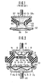
- Fig. 1 is a vertical sectional view of a conventional power unit mount device;
- Fig. 2 is a vertical sectional view of a first embodiment of a power unit mount device in accordance with the present invention;
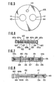
- Fig. 3 is a plan view, partly in section, of a partition plate forming part of the power unit mount device of Fig. 2;
- Fig. 4 is a vertical sectional view of a second embodiment of the power unit mount device in accordance with the present invention;
- Fig. 5 is a plan view of a partition plate forms part of the power unit mount device of Fig. 4;
- Fig. 6 is a vertical sectional view of an example of a partition plate useable in place of the partition plate of Fig. 5;
- Fig. 7 is a vertical sectional view similar to Fig. 6, but showing another example of the partition plate useable in place of the partition plate of Fig. 5;
- Fig. 8 is a vertical sectional view similar to Fig. 6, but showing a further example of the partition plate useable in place of the partition plate of Fig. 5; and
- Fig. 9 is a graph showing the characteristics of the second embodiment of the power unit mount device in terms of the relationship between static-dynamic ratio and frequency.
- To facilitate understanding the present invention, a brief reference will be made to a conventional fluid-filled power unit mount device, depicted in Fig. 1. Such a fluid-filled power unit mount device is, for example, disclosed in Japanese Patent Provisional (First) Publication No. 58-72740. Referring to Fig. 1, the conventional power unit mount device includes a
mount rubber 53 which is securely interposed between abase plate 51 on a power unit side and abase plate 52 on a vehicle body side. Themount rubber 53 is formed therein with aninner space 53a filled with a fluid. Adiaphragm 54 and apartition plate structure 55 is fixedly connected to thebase plate 52 thereby to define anauxiliary chamber 56 between thepartition plate structure 55 and thediaphragm 54. Additionally, thepartition plate structure 55 defines afluid chamber 57 between it and thebase plate 51. Thepartition plate structure 55 includes a valve ormovable mechanism 58 which is movable under large amplitude high frequency vibration and restrained from its movement under large amplitude low frequency vibration. Thevalve mechanism 58 has amovable plate 59 which is formed with anorifice 60 through which thefluid chamber 57 and theauxiliary chamber 56 are communicated with each other. - Such a conventional power unit mount device is configurated to function as follows: To relatively large amplitude vibration in a low frequency range, damping force can be obtained upon resonance in which the fluid within the orifice serves as a mass; and to relatively small amplitude vibration in a high frequency range, damping can be accomplished by suppressing the value of dynamic spring constant of whole the power unit mount device at a predetermined range upon movement of the
movable member 59 of thevalve mechanism 58. Accordingly, the engine mount device is such set that engine shake generated at resonance frequency (for example, of 5-13 Hz) is prevented by providing theorifice 60 with high damping force, and booming noise is prevented from its generation by thevalve mechanism 58 which makes its resonance at a frequency slightly higher than levels of 100-170 Hz at which the booming noise is generated. - However, in the thus set power unit mount device, if the dynamic spring constant of whole the engine mount device at a frequency range of 100-170 Hz is lowered in order to prevent booming noise generation, the
valve mechanism 58 cannot smoothly function at a higher frequency range (for example, of 250-300 Hz) higher than the range of 100-170 Hz because of exceeding the resonance point of thevalve mechanism 58, thereby providing a damping effect deterioration region in which the value of dynamic spring constant of whole the engine mount device considerably rises. The thus rising dynamic spring constant causes high frequency fine vibration due to combustion in an engine to be readily transmitted from the engine to a vehicle body. - Now, the
valve mechanism 58 constitutes a spring system whose resonance frequency fo is expressed by the following equation

- In view of the above description of the conventional power unit mount device, reference is now made to Fig. 2, wherein a first embodiment of a fluid-filled power unit mount device of the present invention is illustrated. The power unit mount device comprises an elastomeric block or
mount rubber 3 is securely interposed between a base plate 1 on a power unit side and abase plate 2 on a vehicle body side. Themount rubber 3 is formed therein with an inner space or cavity 3a. Adiaphragm 4 and apartition plate 6 are securely connected to the base plate 1. Adiaphragm 5 and apartition plate 7 are securely connected to thebase plate 2. A first auxiliary chamber 8 is defined between thediaphragm 4 and thepartition plate 6. A secondauxiliary chamber 9 is defined between thediaphragm 5 and thepartition plate 7. - More specifically, the
mount rubber 3 is securely connected or bonded at its upper section to thepartition plate 6 and at its lower section to a generallyannular support plate 10 by means of adhesion due to vulcanization. Thepartition plate 6 is bent inside at its outer peripheral section and secured onto the base plate 1, in which the outer peripheral section of thediaphragm 4 is securely put between thepartition plate 6 and the base plate 1. Thesupport plate 10 is bent inside at its lower section and secured to thebase plate 2, in which the outer peripheral section of thediaphragm 5 is securely put between thesupport plate 10 and thebase plate 2. A fluid chamber 11 is defined between thepartition plate 6 and thepartition plate 7. An incompressive fluid such as water or oil is filled in thechambers 8, 9, 11. - The
partition plate 6 is provided with a first movable orvalve mechanism 12 which is movable under fine or small amplitude vibration in a predetermined high frequency range (for example, of 100-170 Hz), and restrained in its movement under large amplitude vibration in a predetermined low frequency range (for example, of 5-13 Hz). Thepartition plate 7 is further provided with a second movable orvalve mechanism 13 which functions in the same manner as in the first movable mechanism, and anorifice device 14, as a flow passage with orifice, through which the fluid chamber 11 and the secondauxiliary chamber 9 are communicated with each other. The firstmovable mechanism 12 includes upper andlower plates partition plate 6. The upper andlower plates rods 17 which are loosely inserted in through-holes 6a of thepartition plate 6. The upper andlower plates partition plate 6, respectively. - The second
movable mechanism 13 includes a flexible diaphragm-shapedmember 18 formed of an elastomeric material (such as rubber or elastomer) in which fibrous material is embedded. Theflexible member 18 is securely attached or bonded to thepartition plate 7 in such a manner to coveropenings 7a. Additionally, theorifice device 14 includes a flowpassage defining member 14d which is secured to thepartition plate 7 and in tight contact with theflexible member 18 thereby to define afluid flow passage 14c generally around theopenings 7a. Thefluid flow passage 14c is communicated at one end thereof with the secondauxiliary chamber 9 through an orifice 14a and at the other end thereof with the fluid chamber 11 through anorifice 14b as shown in Fig. 3. The orifice 14a is formed through theflexible member 18 and thepartition plate 7. Theorifice 14b is formed through the top wall of the flowpassage defining member 14d. As shown, thefluid flow passage 14c is S-shaped so as to have a predetermined larger volume. - The base plate 1 is formed with an air vent 1a, and securely provided with a bolt 19 by which the base plate 1 is installed to the power unit. The
base plate 2 is formed with anair vent 2a, and securely provided with abolt 20 by which thebase plate 2 is installed to the vehicle body. It is to be noted that a vibration frequency f1 at which theorifice device 14 exhibits the maximum value of damping ability depends on the equivalent mass of the fluid within theorifice device 14 and on the cross-sectional area of theorifice device 14, i.e., the diameters of theorifices 14a and 14b located at opposite ends of thefluid flow passage 14c. A variety of experiments conducted by the present inventors et al revealed that the frequency f1 lowered as the equivalent mass increased and as the diameter of the orifices decreased. Furthermore, it was also revealed that the damping ability increased as the diameter of the orifices increased. - The manner of operation of the thus configurated power unit mount device will be discussed hereinafter.
- When the large amplitude vibration in the low frequency range (for example, 5-13 Hz) in which engine shake occurs is input to the base plate 1, the
mount rubber 3 largely extends and contracts thereby to cause the volume change of the fluid chamber 11. As a result, the upper orlower plates movable mechanism 12 are brought into close contact with thepartition plate 6, and then theflexible member 18 is fixed to theopenings 7a of thepartition plate 7 by virtue of tensile force of the fiber material contained therein after making a predetermined elastic deformation. Thus, the first and secondmovable mechanisms orifice device 14 makes its resonance vibration, thereby generating a greater damping force. - Furthermore, since the
fluid flow passage 14c of theorifice device 14 has a relatively large volume and a cross-sectional area larger than that of theorifices 14a, 14b, the frequency f, at which the maximum damping ability is exhibited can be set at a predetermined frequency in a relatively low frequency range even in case the diameter of theorifices 14a, 14b are relatively enlarged. Additionally, it is possible to set the diameter of theorifices 14a, 14b larger, thereby raising the damping ability. - When the small amplitude vibration in a high frequency range (for example, of 100-170 Hz) in which booming noise is generated is input, the fluid cannot flow through the
orifice device 14 because the speed of pressure change within the fluid chamber 11 is higher, so that the fluid is confined in the fluid chamber 11. At this time, themount rubber 3 extends and contracts, and the first and secondmovable mechanisms lower plates movable mechanism 12 moves upward and downward while theflexible member 18 extends and contracts, thereby lowering the value of dynamic spring constant of whole the power unit mount device. This suppresses the transmission of the small amplitude vibration from the power unit to the vehicle body. More specifically, since a high damping effect is obtained in the low frequency range by virtue of theorifice device 14, it is possible to set the value of static spring constant of themount rubber 3 at a low value as compared with a conventional engine mount device consisting of a single mount rubber. This can lower the value of dynamic spring constant of themount rubber 3 in the high frequency range (for example, of 100-170 Hz) under cooperation of the effect of the first and secondmovable mechanisms - In a damping effect deterioration region in which the value of dynamic spring constant of whole the engine mount device rises in a higher frequency range (for example, of 250-300 Hz) slightly higher than the above-mentioned high frequency range in which booming noise is generated, the damping effect deterioration of the power unit mount device can be suppressed lower under the combined effects of the first and second
movable mechanisms - Since the resonance frequency fo of each
movable mechanism 
movable mechanism diaphragm auxiliary chambers 8, 9 are defined by a plurality ofdiaphragms - Fig. 4 illustrates a second embodiment of the engine mount device of the present invention. In this embodiment, an elastomeric block or mount
rubber 103 is securely interposed between abase plate 101 on the power unit side and abase plate 102 on the vehicle body side. Themount rubber 103 is formed with an inner space or cavity 103a filled with the incompressive fluid. Adiaphragm 104 and apartition plate 105 are securely connected to thebase plate 102 in such a manner as to define anauxiliary chamber 106 between thediaphagm 104 and thepartition plate 105. More specifically, themount rubber 103 is securely connected or bonded at its upper section to thebase plate 101 and at its lower section to a generallyannular support plate 107 by means of adhesion due to vulcanization. Thesupport plate 107 is bent inside at its lower section to be secured to thebase plate 102, in which the outer peripheral sections of thepartition plate 105 and anannular member 108 are fixedly put between thesupport plate 107 and thebase plate 102 which are incorporated with each other. Thediaphragm 104 is securely attached or bonded at its outer periphery to the inner peripheral section of theannular member 108 by means of adhesion due to vulcanization. Afluid chamber 109 is defined between thepartition plate 105 and thebase plate 101. The incompressive fluid is filled in thechamber 109 and theauxiliary chamber 106. Thepartition plate 105 is provided with anorifice 110 through which thefluid chamber 109 and theauxiliary chamber 106 are communicated with each other. Thepartition plate 105 is further provided with first and second movable orvalve mechanisms 111, 112 each of which is movable uner the small amplitude vibration in the predetermined high frequency range and restrained from its movement under the large amplitude vibration in the predetermined low frequency range. The first movable mechanism 111 includes a flexible diaphragm-shapedmember 113 formed of the elastomeric material in which the fibrous material is embedded. Theflexible member 113 is bonded to the inner peripheral surface of an opening 105a formed through thepartition plate 105 as shown in Fig. 5. The secondmovable mechanism 112 has the same structure as the first movable mechanism 111 and accordingly includes a flexible diaphragm-shapedmember 114 which is the same as theflexible member 113. Theflexible member 114 is bonded to the inner peripheral surface of anopening 105b formed through thepartition plate 105. Additionally, anorifice 110 as a through-hole is formed in thepartition plate 105 as shown in Fig. 5. Thebase plate 101 is provided with abolt 115 by which the base plate is installed to the power unit. Thebase plate 102 is formed with anair vent 102 and provided with abolt 116 by which the base plate is installed to the vehicle body. - With the thus configurated second embodiment engine mount device, the
orifice 110 exhibits the same effect obtained by the conventional engine mount device as shown in Fig. 1, thereby effectively damping the large amplitude vibration in the predetermined low frequency range. However, the first and secondmovable mechanisms 111, 112 function same as the first and secondmovable mechanisms movable mechanisms 111, 112. - This damping effect will be discussed in detail with reference to the test result of Fig. 9. In Fig. 9 whose ordinate axis is dynamic-static ratio (dynamic spring constant/static spring constant) whereas abscissa axis is frequency Hz, a line a indicates the characteristics of the conventional power unit mount device as shown in Fig. 1, a line b that of a conventional power unit mount device consists of a single mount rubber, and a line c that of the second embodiment power unit mount device shown in Figs. 4 and 5.
- The graph of Fig. 9 reveals the fact that the value of dynamic spring constant of the second embodiment power unit mount device can be maintained within a certain range under vibration in the frequency range of 100-170 Hz, and additionally a conspicuous increase in dynamic spring constant of the sense can be suppressed in a frequency range higher than a resonance frequency f2 of the characteristics of the line a. This can suppress the transmission of the small amplitude vibration in the high frequency range of about 250-300 Hz to the vehicle body, while lowering the value of dynamic spring constant. Since the resonance frequency fo is expressed by the equation

flexible member diaphragm member 104. Turning again to Fig. 9, a line d indicates the characteristics of a power unit mount device similar to that of Figs. 4 and 5 except that thepartition plate 105 is provided with three movable mechanisms which are parallelly arranged, in which the maximum value of the dynamic spring constant further lowers and shifts towards high frequency side. - Fig. 6 shows an example of a
partition plate 123 which is usable in place of thepartition plate 105 of the second embodiment power unit mount device shown in Figs. 4 and 5. Thepartition plate 123 is provided with anorifice device 120, and first and secondmovable mechanisms partition plate 123 is formed at its peripheral section with an annularfluid flow passage 120c which forms a middle part of theorifice device 120. An end portion of thefluid flow passage 120c is opened through the orifice 120a to the one side surface of thepartition plate 123. The other end portion of thefluid flow passage 120c is opened through anorifice 120b to the other side surface of thepartition plate 123. Thepartition plate 123 is formed at its central section with right and left chambers or spaces 126,127 which are separated from each other. The right and leftchambers lower plate sections 124, 125 which form part of wall of thepartition plate 123. Theupper plate section 124 is formed with a plurality of through-holes 124a merging in theleft chamber 127, and a plurality of through-holes 124b merging in theright chamber 126. The lower plate section 125 is formed with a plurality of through-holes 125a merging in theleft chamber 127, and a plurality of through-holes 125b merging in theright chamber 126. Amovable plate 128 formed of an elastic or elastomeric material is loosely disposed within theright chamber 126 thereby constituting the firstmovable mechanism 121. Amovable plate 129 made of the elastic or elastomeric material is loosely disposed within theleft chamber 127 thereby constituting the secondmovable mechanism 122. It will be understood that the upper andlower plate sections 124, 125 serve as stoppers for themovable plates movable mechanisms - In case the
partition plate 123 is used in place of thepartition plate 105 of the second embodiment power unit mount device of Figs. 4 and 5, themovable plates lower plate sections 124, 125 under the small amplitude vibration in the predetermined high frequency range, while they 128, 129 are biased against the upper orlower plate section 124, 125 to be restrained from its movement, thus obtaining the same effect as in the second embodiment power unit mount device. In addition, since thefluid flow passage 120c connecting theorifices 120a, 120b has a cross-sectional area larger than that of theorifices 120a, 120b, it is possible to set relatively larger the diameter of theorifices 120a, 120b thereby to obtain high damping effect to low frequency vibration by virtue of the action of fluid mass within thefluid flow passage 120c. It will be understood that the movable plates 128,129 may be formed of the elastomeric material such as rubber or elastomer since they are supported throughout their wide surface by the solid or wall portion of the upper andlower plate sections 124, 125. - Fig. 7 shows another example of a
partition plate 133 useable in place of thepartition plate 105 of the second embodiment power unit mount device shown in Figs. 4 and 5. Thepartition plate 133 is provided with anorifice 130, and first and secondmovable mechanisms partition plate 133 is formed with twoopenings plate member 134 is disposed in theopening 133a in such a manner that its peripheral section is securely connected to an elasticannular member 135 fixedly disposed in theopening 133a, thus constituting the firstmovable mechanism 131 in which theplate member 134 is movable upward and downward. Aplate member 136 is disposed in theopening 133b in such a manner that its peripheral section is securely connected to an elasticannular member 135 fixedly disposed in theopening 133b, thus constituting the secondmovable mechanism 132 in which theplate member 136 is movable upward and downward. Theplate member 136 carries a pipe member through which anorifice 130 is formed. - In case the
partition plate 133 is installed in place of the partition plate of 105 of the second embodiment power unit mount device of Figs. 4 and 5, then theplate members elastic members orifice 130 under such the large amplitude high frequency vibration. Thus, the power unit mount device provided with thepartition plate 133 functions same as the second embodiment power unit mount device. - Fig. 8 shows a further example of a
partition wall 143 useable in place of thepartition plate 105 of the second embodiment power unit mount device. Thepartition plate 143 is provided with a firstmovable mechanism 141 which is substantially the same as the firstmovable mechanism 131 of thepartition plate 133 of Fig. 7 and functions same as themechanism 131. Thepartition plate 143 is further provided with a secondmovable mechanism 142 which includes amovable plate 145 loosely disposed in a chamber or space (no numeral) defined between upper andlower plate sections 144a, 144b serving as stoppers for themovable plate 145. Additionally, anorifice 140 is formed through the wall of thepartition plate 143. - In case this
partition plate 143 is installed in place of thepartition plate 105 of the second embodiment power unit mount device, themovable plate 145 moves between the upper andlower plate sections 144a, 144b under the small amplitude vibration in the predetermined high frequency range and are restrained from its movement upon biased against the upper orlower plate sections 144a, 144b under the large amplitude vibration in the predetermined low frequency vibration. It will be understood that theorifice 140 exhibits damping effect under such large amplitude low frequency vibration. - It will be appreciated that, in order to obtain good damping effect, each first
movable mechanism movable mechanism
Claims (29)
Applications Claiming Priority (2)
| Application Number | Priority Date | Filing Date | Title |
|---|---|---|---|
| JP34296/84 | 1984-02-27 | ||
| JP59034296A JPS60179541A (en) | 1984-02-27 | 1984-02-27 | Liquid charged power unit mount device |
Publications (2)
| Publication Number | Publication Date |
|---|---|
| EP0154268A1 EP0154268A1 (en) | 1985-09-11 |
| EP0154268B1 true EP0154268B1 (en) | 1988-12-21 |
Family
ID=12410191
Family Applications (1)
| Application Number | Title | Priority Date | Filing Date |
|---|---|---|---|
| EP85101977A Expired EP0154268B1 (en) | 1984-02-27 | 1985-02-22 | Fluid-filled power unit mount device |
Country Status (4)
| Country | Link |
|---|---|
| US (1) | US4708329A (en) |
| EP (1) | EP0154268B1 (en) |
| JP (1) | JPS60179541A (en) |
| DE (1) | DE3566873D1 (en) |
Families Citing this family (43)
| Publication number | Priority date | Publication date | Assignee | Title |
|---|---|---|---|---|
| JPS60188637A (en) * | 1984-03-06 | 1985-09-26 | Nissan Motor Co Ltd | Damping support |
| JPH0754131B2 (en) * | 1984-09-07 | 1995-06-07 | 株式会社ブリヂストン | Anti-vibration device |
| FR2589208B1 (en) * | 1985-10-28 | 1989-12-22 | Hutchinson Sa | IMPROVEMENTS ON HYDRAULIC ANTIVIBRATORY SUPPORTS |
| DE3611529A1 (en) * | 1986-04-05 | 1987-10-08 | Freudenberg Carl Fa | ENGINE MOUNT WITH HYDRAULIC DAMPING |
| JPH0799189B2 (en) * | 1986-06-12 | 1995-10-25 | 本田技研工業株式会社 | Fluid filled type anti-vibration device |
| CA1297507C (en) * | 1986-07-16 | 1992-03-17 | Richard Paul Thorn | Fluid filled vibration isolator having plural tunable dynamic stiffnesses |
| DE3629860A1 (en) * | 1986-09-02 | 1988-03-10 | Metzeler Kautschuk | BEARING WITH HYDRAULIC DAMPING |
| FR2609766B1 (en) * | 1987-01-20 | 1989-05-19 | Peugeot | ELASTIC SUPPORT, IN PARTICULAR FOR THE SUSPENSION OF A VEHICLE ENGINE |
| FR2613799B1 (en) * | 1987-04-13 | 1990-12-07 | Peugeot | HYDROELASTIC SUPPORT, IN PARTICULAR FOR THE SUSPENSION OF A VEHICLE ENGINE |
| FR2617930B1 (en) * | 1987-07-07 | 1992-07-31 | Peugeot | HYDROELASTIC SUPPORT, IN PARTICULAR FOR PROVIDING THE SUSPENSION OF AN ENGINE IN A VEHICLE |
| JPS6421238A (en) * | 1987-07-11 | 1989-01-24 | Tokai Rubber Ind Ltd | Fluid enclosing type mount device |
| FR2628496B1 (en) * | 1988-03-08 | 1990-12-21 | Peugeot | ELASTIC CONNECTION WITH HYDRAULIC RIGIDIFICATION |
| US4925162A (en) * | 1988-06-17 | 1990-05-15 | Bridgestone Corporation | Vibration isolating devices |
| JP2811448B2 (en) * | 1988-07-13 | 1998-10-15 | 本田技研工業株式会社 | Fluid-filled engine mount |
| US4880215A (en) * | 1988-08-05 | 1989-11-14 | Tokai Rubber Industries, Ltd. | Fluid-filled elastic mounting structure |
| US4889325A (en) * | 1988-08-15 | 1989-12-26 | Lord Corporation | Fluid filled vibration isolator |
| DE3841193A1 (en) * | 1988-12-07 | 1990-06-21 | Boge Ag | HYDRAULIC DAMPING RUBBER BEARING |
| FR2641594B1 (en) * | 1989-01-10 | 1994-04-29 | Hutchinson | IMPROVEMENTS ON HYDRAULIC ANTI-VIBRATION DEVICES |
| DE3906373A1 (en) * | 1989-03-01 | 1990-09-13 | Freudenberg Carl Fa | ENGINE MOUNT |
| DE3918753C1 (en) * | 1989-06-08 | 1990-07-12 | Fa. Carl Freudenberg, 6940 Weinheim, De | |
| GB2237354A (en) * | 1989-10-27 | 1991-05-01 | Draftex Ind Ltd | A hydroelastic support |
| JP2584569Y2 (en) * | 1989-12-15 | 1998-11-05 | 日産自動車株式会社 | Liquid-enclosed power unit mount |
| US5112032A (en) * | 1991-01-09 | 1992-05-12 | General Motors Corporation | Hydraulic mount with triple decouplers |
| US5263693A (en) * | 1992-04-30 | 1993-11-23 | General Motors Corporation | Tiered decoupler for improved high frequency tuning of hydraulic mounts |
| US5286012A (en) * | 1992-05-07 | 1994-02-15 | Hutchinson | Hydraulic antivibration devices |
| GB2325720B (en) * | 1995-12-08 | 1999-01-20 | Avon Vibration Man Syst Ltd | Hydraulically damped mounting device |
| US5738330A (en) * | 1995-12-11 | 1998-04-14 | Vibro/Dynamics Corp. | Machinery mount with damping means |
| JP3035222B2 (en) * | 1996-07-31 | 2000-04-24 | 鬼怒川ゴム工業株式会社 | Liquid filled type vibration damping device |
| JP3438561B2 (en) * | 1997-12-26 | 2003-08-18 | 東海ゴム工業株式会社 | Liquid filled type vibration damping device |
| JP3767403B2 (en) * | 2001-03-30 | 2006-04-19 | 東海ゴム工業株式会社 | Fluid filled vibration isolator |
| DE10359457A1 (en) * | 2003-12-17 | 2005-07-21 | Carl Freudenberg Kg | hydromount |
| CN103912623B (en) * | 2014-04-21 | 2015-12-30 | 山东大学 | Flexible mechanical fluid power coupling arrangement between Medium or severe type power plant and installation foundation |
| JP6450619B2 (en) * | 2015-03-19 | 2019-01-09 | 株式会社ブリヂストン | Vibration isolator |
| JP6710123B2 (en) * | 2016-07-27 | 2020-06-17 | 住友理工株式会社 | Fluid filled type vibration damping device |
| JP2018115718A (en) * | 2017-01-19 | 2018-07-26 | 株式会社ブリヂストン | Vibration control device |
| US10544851B2 (en) * | 2017-02-23 | 2020-01-28 | Ford Global Technologies, Llc | Vehicular vibration isolation system and apparatus |
| DE102017112168B4 (en) * | 2017-06-01 | 2021-04-29 | Vibracoustic Gmbh | Separating device for separating a working chamber and a compensation chamber of a hydraulically damping bearing as well as a hydraulically damping bearing |
| DE102018102130A1 (en) * | 2018-01-31 | 2019-08-01 | Vibracoustic Gmbh | Hydraulically damping bearing |
| US11959527B2 (en) * | 2018-05-10 | 2024-04-16 | Prospira Corporation | Vibration isolator |
| WO2021090886A1 (en) | 2019-11-07 | 2021-05-14 | 株式会社ブリヂストン | Vibration-damping device |
| US12196284B2 (en) | 2019-11-07 | 2025-01-14 | Prospira Corporation | Vibration-damping device |
| JP7350629B2 (en) | 2019-11-07 | 2023-09-26 | 株式会社プロスパイラ | Vibration isolator |
| CN114728573B (en) | 2019-11-07 | 2025-11-04 | 株式会社普洛斯派 | Vibration isolation device |
Citations (2)
| Publication number | Priority date | Publication date | Assignee | Title |
|---|---|---|---|---|
| DE2727244A1 (en) * | 1976-06-30 | 1978-01-05 | Peugeot | DAMPING DEVICE |
| EP0040290A2 (en) * | 1980-05-21 | 1981-11-25 | Firma Carl Freudenberg | Elastic rubber mount |
Family Cites Families (18)
| Publication number | Priority date | Publication date | Assignee | Title |
|---|---|---|---|---|
| DE2659844C3 (en) * | 1976-05-15 | 1981-04-23 | Audi Nsu Auto Union Ag, 7107 Neckarsulm | Rubber mount with hydraulic damping |
| JPS5549A (en) * | 1978-06-12 | 1980-01-05 | Earth Chemical Co | Neck ring for pet |
| EP0012638B1 (en) * | 1978-12-07 | 1982-03-24 | Automobiles Peugeot | Elastic mounting, particularly for the suspension of a vehicle motor |
| IT1110771B (en) * | 1979-02-09 | 1986-01-06 | Gomma Antivibranti Applic | CUSHIONING SUPPORT FOR THE SUSPENSION OF A SWINGING BODY TO A SUPPORT STRUCTURE, IN PARTICULAR FOR THE SUSPENSION OF THE ENGINE TO THE FRAME OF A VEHICLE |
| DE2950109A1 (en) * | 1979-12-13 | 1981-07-02 | Continental Gummi-Werke Ag, 3000 Hannover | ELASTIC BEARING |
| JPS6015806B2 (en) * | 1980-04-14 | 1985-04-22 | 日産自動車株式会社 | Engine mount device with damper |
| AU523318B2 (en) * | 1980-06-23 | 1982-07-22 | Bridgestone Tire Co. Ltd. | Rubber vibration isolators |
| JPS5784220A (en) * | 1980-11-14 | 1982-05-26 | Aisin Seiki Co Ltd | Composite engine mount for vehicle engine |
| JPS57130826A (en) * | 1981-02-02 | 1982-08-13 | Nissan Motor Co Ltd | Engine mount apparatus with fluid therein |
| DE3104708A1 (en) * | 1981-02-10 | 1982-08-26 | WOCO Franz-Josef Wolf & Co, 6483 Bad Soden-Salmünster | THREE-CHAMBER SHOCK ABSORBER |
| JPS57138423A (en) * | 1981-02-17 | 1982-08-26 | Nissan Motor Co Ltd | Engine mount device filled with fluid |
| DE3142673A1 (en) * | 1981-10-28 | 1983-05-05 | Continental Gummi-Werke Ag, 3000 Hannover | Elastic mount, in particular for the engine in motor vehicles |
| FR2522759A1 (en) * | 1982-03-03 | 1983-09-09 | Hutchinson | IMPROVEMENTS ON MEMBRANE HYDRAULIC SHOCK ABSORBERS |
| DE3225701C2 (en) * | 1982-07-09 | 1986-03-20 | Fa. Carl Freudenberg, 6940 Weinheim | Elastic rubber mount |
| EP0115417B1 (en) * | 1983-01-25 | 1989-04-19 | Avon Industrial Polymers Limited | Hydraulically damped mounting device |
| DE3347273C2 (en) * | 1983-12-28 | 1987-01-15 | Lemförder Metallwaren AG, 2844 Lemförde | Elastic support bearing with a hydraulic damper |
| JPS60155029A (en) * | 1984-01-25 | 1985-08-14 | Nissan Motor Co Ltd | Vibration isolating device containing fluid |
| DE3416431C2 (en) * | 1984-05-04 | 1986-07-31 | Boge Gmbh, 5208 Eitorf | Hydraulically damping rubber mount |
-
1984
- 1984-02-27 JP JP59034296A patent/JPS60179541A/en active Pending
-
1985
- 1985-02-22 DE DE8585101977T patent/DE3566873D1/en not_active Expired
- 1985-02-22 EP EP85101977A patent/EP0154268B1/en not_active Expired
-
1986
- 1986-11-24 US US06/935,108 patent/US4708329A/en not_active Expired - Fee Related
Patent Citations (2)
| Publication number | Priority date | Publication date | Assignee | Title |
|---|---|---|---|---|
| DE2727244A1 (en) * | 1976-06-30 | 1978-01-05 | Peugeot | DAMPING DEVICE |
| EP0040290A2 (en) * | 1980-05-21 | 1981-11-25 | Firma Carl Freudenberg | Elastic rubber mount |
Also Published As
| Publication number | Publication date |
|---|---|
| US4708329A (en) | 1987-11-24 |
| EP0154268A1 (en) | 1985-09-11 |
| JPS60179541A (en) | 1985-09-13 |
| DE3566873D1 (en) | 1989-01-26 |
Similar Documents
| Publication | Publication Date | Title |
|---|---|---|
| US4708329A (en) | Fluid-filled power unit mount device | |
| EP0119796B1 (en) | Vibration damping device | |
| US5499799A (en) | Vibration isolating apparatus | |
| US4679778A (en) | Fluid-containing power unit mounting device | |
| US5167403A (en) | Fluid-filled elastic mount having two orifice passages one of which is selectively opened and closed by means of vacuum pressure | |
| US4657232A (en) | Hydraulically damped mounting device | |
| US4709898A (en) | Fluid-sealed engine mounting | |
| EP0058408A2 (en) | Fluid-filled engine mount device | |
| EP0115417A2 (en) | Hydraulically damped mounting device | |
| CA1248561A (en) | Resilient rubber bearing with integrated hydraulic damping | |
| US6485005B1 (en) | Hydraulic mount with gas spring supported decoupler | |
| JPH0285537A (en) | Fluid charged mount device | |
| JPH08210424A (en) | Fluid-filled mounting device | |
| US7344128B2 (en) | Fluid-filled type vibration-damping device | |
| US5076550A (en) | Fluid filled elastomeric damping device | |
| JP2011133031A (en) | Fluid filled vibration isolator | |
| JP4075066B2 (en) | Fluid filled engine mount | |
| JPH0247615B2 (en) | ||
| JPH02129426A (en) | Fluid enclosed type mount device | |
| EP0324613A2 (en) | Hydraulically damped mounting device | |
| JP2003004088A (en) | Liquid sealed vibration isolator | |
| JPS63275827A (en) | Vibrationproofing method using liquid sealing mounting device | |
| JP3838280B2 (en) | Liquid-filled engine mount | |
| JP3975296B2 (en) | Fluid filled vibration isolator | |
| JPH0417291B2 (en) |
Legal Events
| Date | Code | Title | Description |
|---|---|---|---|
| PUAI | Public reference made under article 153(3) epc to a published international application that has entered the european phase |
Free format text: ORIGINAL CODE: 0009012 |
|
| 17P | Request for examination filed |
Effective date: 19850222 |
|
| AK | Designated contracting states |
Designated state(s): DE GB |
|
| 17Q | First examination report despatched |
Effective date: 19870309 |
|
| GRAA | (expected) grant |
Free format text: ORIGINAL CODE: 0009210 |
|
| AK | Designated contracting states |
Kind code of ref document: B1 Designated state(s): DE GB |
|
| REF | Corresponds to: |
Ref document number: 3566873 Country of ref document: DE Date of ref document: 19890126 |
|
| PLBE | No opposition filed within time limit |
Free format text: ORIGINAL CODE: 0009261 |
|
| STAA | Information on the status of an ep patent application or granted ep patent |
Free format text: STATUS: NO OPPOSITION FILED WITHIN TIME LIMIT |
|
| 26N | No opposition filed | ||
| PGFP | Annual fee paid to national office [announced via postgrant information from national office to epo] |
Ref country code: GB Payment date: 19940214 Year of fee payment: 10 |
|
| PGFP | Annual fee paid to national office [announced via postgrant information from national office to epo] |
Ref country code: DE Payment date: 19940224 Year of fee payment: 10 |
|
| PG25 | Lapsed in a contracting state [announced via postgrant information from national office to epo] |
Ref country code: GB Effective date: 19950222 |
|
| GBPC | Gb: european patent ceased through non-payment of renewal fee |
Effective date: 19950222 |
|
| PG25 | Lapsed in a contracting state [announced via postgrant information from national office to epo] |
Ref country code: DE Effective date: 19951101 |