EP0153882B1 - Hydraulische Bremse - Google Patents
Hydraulische Bremse Download PDFInfo
- Publication number
- EP0153882B1 EP0153882B1 EP19850301474 EP85301474A EP0153882B1 EP 0153882 B1 EP0153882 B1 EP 0153882B1 EP 19850301474 EP19850301474 EP 19850301474 EP 85301474 A EP85301474 A EP 85301474A EP 0153882 B1 EP0153882 B1 EP 0153882B1
- Authority
- EP
- European Patent Office
- Prior art keywords
- fluid
- shaft
- rotational speed
- valve
- impeller
- Prior art date
- Legal status (The legal status is an assumption and is not a legal conclusion. Google has not performed a legal analysis and makes no representation as to the accuracy of the status listed.)
- Expired
Links
Images


Classifications
-
- F—MECHANICAL ENGINEERING; LIGHTING; HEATING; WEAPONS; BLASTING
- F16—ENGINEERING ELEMENTS AND UNITS; GENERAL MEASURES FOR PRODUCING AND MAINTAINING EFFECTIVE FUNCTIONING OF MACHINES OR INSTALLATIONS; THERMAL INSULATION IN GENERAL
- F16D—COUPLINGS FOR TRANSMITTING ROTATION; CLUTCHES; BRAKES
- F16D57/00—Liquid-resistance brakes; Brakes using the internal friction of fluids or fluid-like media, e.g. powders
- F16D57/04—Liquid-resistance brakes; Brakes using the internal friction of fluids or fluid-like media, e.g. powders with blades causing a directed flow, e.g. Föttinger type
Definitions
- the present invention relates to a hydraulic brake in accordance with the preamble of Claim 1.
- a water wheel or a wind mill is employed to utilise and recover fluid energy in order to provide power to a load.
- the rotational speed of the water wheel or wind mill is affected. For instance, when the magnitude of the load is decreased, the water wheel or wind mill is rotated faster because the flowing energy is usually unchanged over a certain period. Therefore, it has been necessary to control, limit or maintain such rotational speed of the water wheel or wind mill to allow for cases when the magnitude of the load varies.
- a flow control valve accompanied by a regulating means has been disposed upstream of the wheel.
- wheel is employed for convenience to mean a water wheel or wind mill).
- the regulating means comprises, for example, an actuator for actuating the flow control valve and a sensor sensing the rotational speed so as to determine the degree of required operation by the actuator, and such regulating means has been of a relatively large size which has made it expensive and has required a large space for installation.
- An hydraulic brake in accordance with the preamble of Claim 1 is known from US ⁇ A ⁇ 3 958 671 in which the supply of operating fluid forms in a reservoir an annulus which will develop only when the rotational speed of the rotatable impeller is sufficient to render the brake operative.
- the impeller portion can receive such fluid from the reservoir only when the pressure in the radially innermost portion of the interior of the reservoir increases in response to admission of compressed air.
- the means for controlling the volume of said operating liquid within said impeller portion varies said volume in response to variations in the rotational speed of said shaft, and said means comprises
- a valve responsive to the rotational speed of said shaft and disposed in said fluid conduit.
- the braking force of the above construction naturally depends on the volume of the fluid contained within the impeller portion and, therefore, the braking force is capable of being regulated by controlling the amount of fluid fed into the impeller portion. Since the regulation of the fluid being fed is arranged so that fluid is not supplied to the impeller portion until the rotational speed reaches a predetermined level no braking force is generated during the operation of a wheel which is rotated under the predetermined level of speed, and the braking force is produced as the rotational speed is increased beyond the predetermined level.
- the hydraulic brake can be used in a water-wheel apparatus for recovering fluid energy disposed in a fluid stream and mounted on a rotatable shaft.
- the present invention relies on the phenomenon described above.
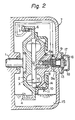
- FIG. 2 wherein an embodiment of a hydraulic brake according to the present invention is schematically illustrated in a cross section.
- a rotatable shaft 1 adapted to be driven by the wheel has attached at the end thereof a rotatable impeller 2.
- a stationary impeller 8 is stationarily mounted on the inner-side wall of a housing 7 in opposing relation to the rotatable impeller 2 so as to compose a main part "X" of the hydraulic brake similar, in construction, to a so-called hydraulic coupling.
- the main part is hereinafter referred to as an impeller portion "X”.
- the housing 7 includes a portion 15 which serves as an oil sump.
- the rotatable impeller 2 comprises a peripheral flange 4 at the outer peripheral portion thereof and the flange 4 is so configured as to form an annular groove 3 in which an oil or fluid ring is produced by a centrifugal force when the impeller 2 is driven to rotate while immersing the flange 4 partially in the oil at the sump 15.
- a rotor casing 10 is attached to the rotatable impeller 2 so as to enclose the stationary impeller 8 therein without interfering with the relative rotation therebetween.
- a flow control valve 9 is disposed in the housing 7 and is adapted to regulate the amount of oil 14 in the impeller portion "X" of the hydraulic brake.
- the oil 14 used for braking is introduced into the impeller portion "X" by means of a scoop tube 6 through the valve 9.
- a valve body 9a of the valve 9 is normally urged to close the valve by a spring 13.
- the valve body 9a is adapted to receive a hydraulic pressure from a rear chamber 12 at the side opposite the spring 13.
- the rear chamber 12 is coupled with the oil ring in the flange groove 3 through a scoop tube 5 supplied with a pressurized oil from the oil ring formed within the groove 3, the pressure being generated by the centrifugal force cause by the rotation. Therefore, the position of the valve body 9a is determined by the spring 13 and the hydraulic pressure in the rear chamber 12 derived from the rotation of the flange groove 3.
- a discharge port or ports 11 are provided in the peripheral wall of the rotor casing 10.
- the amount of oil 14 in the impeller portion is, thus, regulated by the valve 9 and the discharge port (or ports) 11 and this amount determines the magnitude of the braking force.
- the spring 13 is adjustable by an adjusting head 16 threadably engaged in the valve 9 so as to set the pressure valve in the chamber 12 for commencement of the opening of the valve 9 or movement of the valve body 9a away from a valve seat 9b.
- the head 16 is fixed in place by a lock nut 17 after the adjustment and is covered by a cap 18.
- the hydraulic pressure in the rear chamber 12 overcomes the force of the spring 13 to open the valve 9 whereby the fluid or oil is introduced as the oil 14 into the impeller portion "X" through the scoop tube 6.
- the amount of oil 14 introduced is stabilized after balancing the amount fed to the impeller portion through the scoop tube 6 and the value 9 and the amount discharged from the discharge port(s) 11 so that the braking force corresponding to the amount of oil 14 is applied to the shaft 3.
- the opening degree of the valve becomes larger.
- valve 9 If the valve 9 is fully opened, the oil 14 within the impeller portion of the impellers 2 and 8 will completely fill the impeller portion. Further increase in the speed of the shaft will produce a higher braking force in proportion to the cubic multiplication of the rotational speed (number of revolutions per minute).
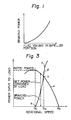
- Fig. 3 The operating condition of the hydraulic brake explained above is illustrated in Fig. 3 with respect to the relationship between the rotational speed, i.e. number of revolutions per minute (in abscissa) and the braking power applied to the rotatable shaft (in ordinate) in a case where the hydraulic brake is directly coupled to the rotatable shaft of the wheel.
- N 1 rotational speed (number of revolutions per minute) at the rated power
- N 2 rotational speed (number of revolutions per minute) where the net input power to the load becomes zero
- N r rotational speed (number of revolutions per minute) without any restraint.
- the performance curve of the hydraulic brake shown in Fig. 2 is illustrated as the curve " ⁇ " in Fig. 3. From this curve "13", it may be understood that the rotational speed (number of revolutions per minute) may be controlled for any power input to the load within a range between N 1 and N 2 wherein N 1 is as defined above (i.e. the number of revolutions per minute at the rated power) and N 2 is the number of revolutions where curves "a" and "13” intersect each other and the net input power to the load becomes zero.
- the point “c” on the curve “13” represents the condition in a case where the oil 14 completely fills the impeller portion.
- the vertical length between the curve "a” and “ ⁇ ” is the net power to be input to the load and the vertical length between the curve "13" and the abscissa corresponds to the braking power consumed in addition to the net power which actually drives the load.
- a flow control valve 29 is employed in place of the valve 9 of the first embodiment.
- This valve 29 is actuated to control the opening degree by a weight governor 23 which is responsive to the rotational speed of the shaft 1'.
- the governor 23 comprises spring plates 21 and weights 22 and is coupled to a valve body 29a.
- the spring plates 21 serve to normally urge the valve body towards a valve seat 29b to thereby close the valve 29.
- the weights 22 are caused to move radially outwardly so as to move the coupled valve body 29a away from the valve seat 29b, thus opening the valve.
- the rotational speed at which the valve commences its opening is pre-set.
- FIG. 5 there is shown a hydraulic generator associated with a hydraulic brake according to the present invention.
- the hydraulic brake incorporated in this example is designated as "A" in Fig. 5 and it corresponds to the first embodiment illustrated in Fig. 2.
- a shaft 31 is rotatably supported by bearings 32 and 33 which are installed in a housing 34. At the lower end of the shaft 31, a water wheel 35 is secured and, at the upper end thereof, the hydraulic brake "A" is coupled. Between the bearings 32 and 33, a rotor 36 of the generator is mounted on the shaft 31 and a stator 37 of the generator is secured in the housing 34 in opposit- ing relation to the rotor 36. A sealing means such as a mechanical seal 38 is disposed around the shaft 31 between the rotor 36 and the water wheel 35.
- the volume of the fluid within the impellers portion is regulated by the pressure in response to the rotational speed, control of such volume may also be effected by shifting the position of the inlet port of the scoop tube directly in response to a change in the centrifugal force so that the volume of fluid within the impeller portion may be varied from zero to an amount corresponding to the point "b" in Fig. 2.
Landscapes
- Engineering & Computer Science (AREA)
- General Engineering & Computer Science (AREA)
- Mechanical Engineering (AREA)
- Braking Arrangements (AREA)
Claims (6)
Priority Applications (1)
| Application Number | Priority Date | Filing Date | Title |
|---|---|---|---|
| AT85301474T ATE44081T1 (de) | 1984-03-02 | 1985-03-04 | Hydraulische bremse. |
Applications Claiming Priority (4)
| Application Number | Priority Date | Filing Date | Title |
|---|---|---|---|
| JP3865684A JPS60184731A (ja) | 1984-03-02 | 1984-03-02 | 液体ブレ−キ |
| JP38655/84 | 1984-03-02 | ||
| JP38656/84 | 1984-03-02 | ||
| JP59038655A JPS60184973A (ja) | 1984-03-02 | 1984-03-02 | 液体ブレ−キを備えた水車 |
Publications (3)
| Publication Number | Publication Date |
|---|---|
| EP0153882A2 EP0153882A2 (de) | 1985-09-04 |
| EP0153882A3 EP0153882A3 (en) | 1986-08-13 |
| EP0153882B1 true EP0153882B1 (de) | 1989-06-14 |
Family
ID=26377930
Family Applications (1)
| Application Number | Title | Priority Date | Filing Date |
|---|---|---|---|
| EP19850301474 Expired EP0153882B1 (de) | 1984-03-02 | 1985-03-04 | Hydraulische Bremse |
Country Status (2)
| Country | Link |
|---|---|
| EP (1) | EP0153882B1 (de) |
| DE (1) | DE3571068D1 (de) |
Families Citing this family (1)
| Publication number | Priority date | Publication date | Assignee | Title |
|---|---|---|---|---|
| US9790922B2 (en) | 2013-07-04 | 2017-10-17 | Orenda Energy Solutions Inc. | Overrun protection for wind turbines |
Family Cites Families (3)
| Publication number | Priority date | Publication date | Assignee | Title |
|---|---|---|---|---|
| DE2361351C3 (de) * | 1973-12-08 | 1978-09-28 | Voith Getriebe Kg, 7920 Heidenheim | Hydrodynamische Bremsanlage für ein vorzugsweise nichtantreibbares Rad eines Fahr- oder Flugzeuges |
| DE2507118C2 (de) * | 1974-11-06 | 1983-12-01 | J.M. Voith Gmbh, 7920 Heidenheim | Hydrodynamische Bremsanlage für ein vorzugsweise nichtantreibbares Rad eines Fahr- oder Flugzeuges |
| JPS5918581B2 (ja) * | 1977-03-17 | 1984-04-27 | フオイト・ツルボ・ゲ−・エム・ベ−・ハ−・ウント・コンパニ−・カ−・ゲ− | 流体力学的制動装置 |
-
1985
- 1985-03-04 EP EP19850301474 patent/EP0153882B1/de not_active Expired
- 1985-03-04 DE DE8585301474T patent/DE3571068D1/de not_active Expired
Also Published As
| Publication number | Publication date |
|---|---|
| EP0153882A2 (de) | 1985-09-04 |
| EP0153882A3 (en) | 1986-08-13 |
| DE3571068D1 (en) | 1989-07-20 |
Similar Documents
| Publication | Publication Date | Title |
|---|---|---|
| US4070132A (en) | Variable performance pump | |
| US4597481A (en) | Hydrodynamic control coupling | |
| WO1991014853A1 (en) | Control system for regulating the axial loading of a rotor of a fluid machine | |
| CA2385897C (en) | Variable flow impeller-type water pump with movable shroud | |
| US5139125A (en) | Temperature sensitive type fluid fan coupling apparatus | |
| JP2008542660A (ja) | 流体摩擦クラッチ | |
| US4201050A (en) | Fluid coupling | |
| US1873688A (en) | Hydraulic clutch | |
| EP0153882B1 (de) | Hydraulische Bremse | |
| US4086766A (en) | Fluid coupling | |
| US4610341A (en) | Fluid friction clutch | |
| US4669262A (en) | Hydrodynamic control coupling | |
| US4194360A (en) | Power take-off arrangements | |
| US810955A (en) | Means for regulating turbines. | |
| US4784247A (en) | Viscous fluid coupling | |
| CN107893702A (zh) | 一种燃气轮机燃油调节装置 | |
| JPS59190521A (ja) | 粘性流体継手 | |
| US4557674A (en) | Flow sensing speed control for pressure fluid motor | |
| JPS60184973A (ja) | 液体ブレ−キを備えた水車 | |
| US3625627A (en) | Speed to pressure transducer | |
| US2701313A (en) | Air supply to turbine runners of hydroelectric power plants | |
| US4574924A (en) | Rotary shaft speed limiting arrangement | |
| US4032252A (en) | Pressure gas engine | |
| EP1579106B1 (de) | Hoch geschwindigkeitsdruckluftmotor mit druckaktiviertem drehzahlregler | |
| US4057360A (en) | Pressure gas engine |
Legal Events
| Date | Code | Title | Description |
|---|---|---|---|
| PUAI | Public reference made under article 153(3) epc to a published international application that has entered the european phase |
Free format text: ORIGINAL CODE: 0009012 |
|
| AK | Designated contracting states |
Designated state(s): AT DE FR GB IT NL SE |
|
| PUAL | Search report despatched |
Free format text: ORIGINAL CODE: 0009013 |
|
| AK | Designated contracting states |
Kind code of ref document: A3 Designated state(s): AT DE FR GB IT NL SE |
|
| 17P | Request for examination filed |
Effective date: 19870117 |
|
| 17Q | First examination report despatched |
Effective date: 19880126 |
|
| GRAA | (expected) grant |
Free format text: ORIGINAL CODE: 0009210 |
|
| AK | Designated contracting states |
Kind code of ref document: B1 Designated state(s): AT DE FR GB IT NL SE |
|
| PG25 | Lapsed in a contracting state [announced via postgrant information from national office to epo] |
Ref country code: NL Effective date: 19890614 Ref country code: IT Free format text: LAPSE BECAUSE OF FAILURE TO SUBMIT A TRANSLATION OF THE DESCRIPTION OR TO PAY THE FEE WITHIN THE PRESCRIBED TIME-LIMIT;WARNING: LAPSES OF ITALIAN PATENTS WITH EFFECTIVE DATE BEFORE 2007 MAY HAVE OCCURRED AT ANY TIME BEFORE 2007. THE CORRECT EFFECTIVE DATE MAY BE DIFFERENT FROM THE ONE RECORDED. Effective date: 19890614 Ref country code: AT Effective date: 19890614 |
|
| REF | Corresponds to: |
Ref document number: 44081 Country of ref document: AT Date of ref document: 19890615 Kind code of ref document: T |
|
| REF | Corresponds to: |
Ref document number: 3571068 Country of ref document: DE Date of ref document: 19890720 |
|
| ET | Fr: translation filed | ||
| NLV1 | Nl: lapsed or annulled due to failure to fulfill the requirements of art. 29p and 29m of the patents act | ||
| PG25 | Lapsed in a contracting state [announced via postgrant information from national office to epo] |
Ref country code: GB Effective date: 19900304 |
|
| PLBE | No opposition filed within time limit |
Free format text: ORIGINAL CODE: 0009261 |
|
| STAA | Information on the status of an ep patent application or granted ep patent |
Free format text: STATUS: NO OPPOSITION FILED WITHIN TIME LIMIT |
|
| 26N | No opposition filed | ||
| GBPC | Gb: european patent ceased through non-payment of renewal fee | ||
| EAL | Se: european patent in force in sweden |
Ref document number: 85301474.4 |
|
| PGFP | Annual fee paid to national office [announced via postgrant information from national office to epo] |
Ref country code: SE Payment date: 19990225 Year of fee payment: 15 |
|
| PGFP | Annual fee paid to national office [announced via postgrant information from national office to epo] |
Ref country code: FR Payment date: 19990330 Year of fee payment: 15 |
|
| PGFP | Annual fee paid to national office [announced via postgrant information from national office to epo] |
Ref country code: DE Payment date: 19990331 Year of fee payment: 15 |
|
| PG25 | Lapsed in a contracting state [announced via postgrant information from national office to epo] |
Ref country code: SE Free format text: LAPSE BECAUSE OF NON-PAYMENT OF DUE FEES Effective date: 20000305 |
|
| EUG | Se: european patent has lapsed |
Ref document number: 85301474.4 |
|
| PG25 | Lapsed in a contracting state [announced via postgrant information from national office to epo] |
Ref country code: FR Free format text: LAPSE BECAUSE OF NON-PAYMENT OF DUE FEES Effective date: 20001130 |
|
| REG | Reference to a national code |
Ref country code: FR Ref legal event code: ST |
|
| PG25 | Lapsed in a contracting state [announced via postgrant information from national office to epo] |
Ref country code: DE Free format text: LAPSE BECAUSE OF NON-PAYMENT OF DUE FEES Effective date: 20010103 |