EP0153335B1 - Verfahren zur erzeugung von strukturen - Google Patents
Verfahren zur erzeugung von strukturen Download PDFInfo
- Publication number
- EP0153335B1 EP0153335B1 EP84902889A EP84902889A EP0153335B1 EP 0153335 B1 EP0153335 B1 EP 0153335B1 EP 84902889 A EP84902889 A EP 84902889A EP 84902889 A EP84902889 A EP 84902889A EP 0153335 B1 EP0153335 B1 EP 0153335B1
- Authority
- EP
- European Patent Office
- Prior art keywords
- membrane
- foam
- panels
- interior
- applying
- Prior art date
- Legal status (The legal status is an assumption and is not a legal conclusion. Google has not performed a legal analysis and makes no representation as to the accuracy of the status listed.)
- Expired
Links
- 238000000034 method Methods 0.000 title claims description 40
- 239000012528 membrane Substances 0.000 claims abstract description 59
- 239000006260 foam Substances 0.000 claims abstract description 56
- 238000005507 spraying Methods 0.000 claims abstract 6
- 239000000463 material Substances 0.000 claims description 10
- 230000002093 peripheral effect Effects 0.000 claims description 6
- 230000004888 barrier function Effects 0.000 claims description 4
- 238000010276 construction Methods 0.000 claims description 4
- 238000005520 cutting process Methods 0.000 claims description 4
- 238000009428 plumbing Methods 0.000 claims description 4
- 239000000565 sealant Substances 0.000 claims description 4
- 238000009432 framing Methods 0.000 claims description 3
- 238000007789 sealing Methods 0.000 claims 2
- 239000011493 spray foam Substances 0.000 claims 1
- 239000000126 substance Substances 0.000 abstract description 4
- 239000007921 spray Substances 0.000 abstract description 3
- 239000011248 coating agent Substances 0.000 description 4
- 238000000576 coating method Methods 0.000 description 4
- 239000004744 fabric Substances 0.000 description 4
- 239000011505 plaster Substances 0.000 description 4
- 229920002635 polyurethane Polymers 0.000 description 3
- 239000004814 polyurethane Substances 0.000 description 3
- 230000002787 reinforcement Effects 0.000 description 2
- 238000005266 casting Methods 0.000 description 1
- 230000000295 complement effect Effects 0.000 description 1
- 239000002131 composite material Substances 0.000 description 1
- 239000002537 cosmetic Substances 0.000 description 1
- 230000006866 deterioration Effects 0.000 description 1
- 239000003063 flame retardant Substances 0.000 description 1
- 239000006261 foam material Substances 0.000 description 1
- 238000005187 foaming Methods 0.000 description 1
- 238000009413 insulation Methods 0.000 description 1
- 239000007788 liquid Substances 0.000 description 1
- 238000004519 manufacturing process Methods 0.000 description 1
- 238000012986 modification Methods 0.000 description 1
- 230000004048 modification Effects 0.000 description 1
- 238000000465 moulding Methods 0.000 description 1
- 239000003973 paint Substances 0.000 description 1
- 239000004033 plastic Substances 0.000 description 1
- 229920003023 plastic Polymers 0.000 description 1
- 239000011120 plywood Substances 0.000 description 1
- 239000011148 porous material Substances 0.000 description 1
- 230000003014 reinforcing effect Effects 0.000 description 1
- 230000000630 rising effect Effects 0.000 description 1
- 230000000007 visual effect Effects 0.000 description 1
Images

Classifications
-
- E—FIXED CONSTRUCTIONS
- E04—BUILDING
- E04B—GENERAL BUILDING CONSTRUCTIONS; WALLS, e.g. PARTITIONS; ROOFS; FLOORS; CEILINGS; INSULATION OR OTHER PROTECTION OF BUILDINGS
- E04B1/00—Constructions in general; Structures which are not restricted either to walls, e.g. partitions, or floors or ceilings or roofs
- E04B1/35—Extraordinary methods of construction, e.g. lift-slab, jack-block
-
- E—FIXED CONSTRUCTIONS
- E04—BUILDING
- E04B—GENERAL BUILDING CONSTRUCTIONS; WALLS, e.g. PARTITIONS; ROOFS; FLOORS; CEILINGS; INSULATION OR OTHER PROTECTION OF BUILDINGS
- E04B1/00—Constructions in general; Structures which are not restricted either to walls, e.g. partitions, or floors or ceilings or roofs
- E04B1/16—Structures made from masses, e.g. of concrete, cast or similarly formed in situ with or without making use of additional elements, such as permanent forms, substructures to be coated with load-bearing material
- E04B1/164—Structures made from masses, e.g. of concrete, cast or similarly formed in situ with or without making use of additional elements, such as permanent forms, substructures to be coated with load-bearing material with vertical and horizontal slabs, only the horizontal slabs being partially cast in situ
-
- E—FIXED CONSTRUCTIONS
- E04—BUILDING
- E04G—SCAFFOLDING; FORMS; SHUTTERING; BUILDING IMPLEMENTS OR AIDS, OR THEIR USE; HANDLING BUILDING MATERIALS ON THE SITE; REPAIRING, BREAKING-UP OR OTHER WORK ON EXISTING BUILDINGS
- E04G11/00—Forms, shutterings, or falsework for making walls, floors, ceilings, or roofs
- E04G11/04—Forms, shutterings, or falsework for making walls, floors, ceilings, or roofs for structures of spherical, spheroid or similar shape, or for cupola structures of circular or polygonal horizontal or vertical section; Inflatable forms
- E04G11/045—Inflatable forms
Definitions
- the present invention relates generally to a method for forming a structure, and more specifically to a method for constructing a building which may be used as a dwelling, the method comprising the steps of:
- US-A-4,241,555 is of interest since it teaches the use of a composite panel structure and an associated method of manufacturing in which the building panel has an expanded plastic core which is first molded and then removed from the mold so as to allow reinforcing strips to be placed on the front and back surfaces thereof.
- the instant application is easily distinguished in that the structure according to the disclosure is itself molded over a form created from wall panels and an inflated or supported membrane so that the forming and molding process also provides the structural shell which supports the structure.
- the panels formed according to US ⁇ A ⁇ 4,241,555 are prefabricated and then assembled, which is not the case in the instant disclosure.
- US-A-3,815,301 teaches the use of applying polyurethane on a roof to form the roof and seal it into a single unit. Thus a supporting surface is provided upon which the polyurethane is to be sprayed.
- structures of conventional configurations can be erected using the method of the instant disclosure.
- the inflatable membrane which can be supported in any desired configuration, forms a surface on which foam material is sprayed to form the roof of the structure, thereby eliminating the need to erect structural members upon which a roof is built.
- the configuration of the roof portion can be predetermined by adjusting the draping of the membrane upon which the foam is sprayed, thereafter using air pressure to inflate the membrane to the convex proturber- ance which represents the form upon which the roof is fashioned.
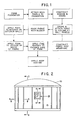
- reference numeral 10 refers generally to a structure formed according to the method of the instant invention.
- step (a) in the flowchart involves pouring a foundation slab of concrete 11 or the like upon which to erect a structure.
- the foundation slab has an outer peripheral edge including a stepped portion 12 with a vertical baseboard 13 which was part of the form into which the concrete was poured.
- the baseboard 13 is left intact after the remainder of the concrete form is removed.
- the inner wall panels 14 and the outer wall panels 15 are attached to the baseboard 13 and the slab 11 by means of fasteners 16.
- the wall panels 14 and 15 may consist of sheets of plywood or any similar substance which can be readily flexed for conformational engagement with the peripheral edges of the slab 11 if the slab is nonrectilinear in configuration.
- a slab may be poured in a circular configuration such that two circles intersect, or are tangential, thereby requiring the wall panels 14 and 15 to conform to curved peripheral surfaces along the slab 11. Therefore, a material must be chosen for wall panels which is flexible enough to conform to various configurations yet provide the structural integrity to stand up alone.
- step (b) the wall panels 14 and 15 are attached to the slab somewhat above the step of stepped portion 12.
- One inner panel 14 is applied to the slab first, then an outer panel 15 is applied half-lapping the inner panel such that adjacent edges 1 of neighbouring inner panels 14 directedly underlie an outer panel 15, as best shown in Figure 5.
- This overlapping configuration of inner and outer panels is continued around the entire periphery of the slab 11 until a contiguous wall form is constructed.
- the outer panels 15 may be adhesively bonded to the inner panels 14 to ensure structural integrity and conformational engagement.
- step (c) after a contiguous wall panel form has been constructed, prefabricated doors and windows may be installed by cutting appropriately sized holes in the wall panels then installing windows 22, doors, or the like as shown in Figure 4. After the desired windows and doors have been framed into the wall panels 14 and 15, then the electrical and plumbing conduits are applied accordingly to the interior surface of the inner wall panel. Similarly, any interior walls designed to carry electrical conduit may be framed out at this point or subsequent to inflating the roof membrane.
- a fabric membrane is constructed from any flexible but strong membrane material or fabric such as cloth, poly- ethelene or the like.
- the membrane 18 must be relatively impervious to air flow, or if it is not, it must receive a coating of a sealant to close any pores in the membrane.
- the membrane 18 need not be formed in any particular shape, as long as it is large enough to encompass the perimeter defined by the wall panels 14 and 15. If necessary, bolts of fabric may be sewn together to form a large sheet capable of encompassing the entire structure.
- the membrane is draped over the entire structure such that middle portions of the membrane hang lower than peripheral portions of the membrane which will be attached to the top of the wall panels 14 and 15.
- the shape and configuration of the membrane 18 is then adjusted, keeping in mind that when attached and inflated it will become the converse of the configuration observed in the draped mode.
- the height and configuration of the ceiling to be formed is predetermined by adjusting the drape of the membrane 18 to a contour complemental to the shape desired to be made prior to inflation of same.
- the membrane 18 may be attached to the upper edge of the outer wall panel 15 by means of a strip 19 which is attached to the upper peripheral edge of the outer wall panel 15 with the membrane 18 captured therebetween.
- the strip 19 may be placed on the interior panel 14 by placing the strip on the interior surface, as shown in phantom in Figure 5.
- an air blower is used to draw air from the outside of the structure to the inside of the structure, thereby creating a slight high pressure area within the structure forces the membrane 18 to inflate and rise upwardly to the configuration desired.
- the strip 19 holds the membrane 18 in place and seals same along the entire upper periphery of the wall panels 14 and 15.
- the membrane 18 may also be supported by temporary structural members (not shown) in order to form roof shapes complemental with a desired configuration which is more. readily achieved by suspending the membrane 18 rather than inflating it.
- a foam substance is then applied to the interior or exterior surfaces of the structure including the wall panels 14 and 15, but not the windows and doors, and the membrane 18 which forms a template upon which the foam is sprayed.
- the foam may be, but is not limited to, a polyurethane fire retardant foam which is sprayed onto desired surfaces.
- the foam is sprayed onto the interior surfaces, the foam 20 adhering to the interior wall panels 14 and the interior of the membrane 18, as shown in Figures 3, 4, and 5.
- the foam thus forms an interior wall 20 which is sprayed in sufficient thickness to approach the raised portion of the framing 21 of the window 22 which has been installed in the wall panels 14 and 15.
- the foam forms a window casement around the window framing 21 while simultaneously forming the interior wall surface 20.
- the foam components are sprayed together in a liquid form thereafter capturing gas in elemental bubbles and raising or increasing in thickness forming a hard shell several inches thick.
- the foam spray is applied in layers until a desired thickness is reached.
- the foam layers 20 may be applied to the exterior surfaces of the structure leaving the interior surfaces without foam.
- a third embodiment contemplates applying the foam layer 20 to both the interior and exterior surfaces in a sandwich-type fashion with an optional structural reinforcement web 24 captured within the foam.
- the foam is applied to the interior surfaces thereby covering and hiding any electrical and/or plumbing conduits that have been applied to the interior surfaces of the structure, thereby eliminating the problems associated with cosmetic cover-up at a later time.
- the foam is applied to either the outside or the inside surfaces of the membrane 18 and wall panels 14 and 15. If the foam is applied to the outside of the panels 14 and 15, then the plumbing and electrical conduits are also installed on the outside so that the foam will cover them.
- a fire barrier 23 is applied to the exposed side of the foam layer 20.
- the fire barrier 23 may be a thin coat of conventional plaster or the like which forms an attractive textured interior wall surface which may thereafter be painted if desired.
- plaster applied to the inner surface of the foam comprising the roof portion of the structure provides an attractive textured surface which may be painted or left as it is. If the foam is applied to the outside of panels 14 and 15, then so is the plaster 23.
- a final coat of roof coating may be applied to the exterior foam surfaces in order to preserve same from the elements including rain and sun which may cause foam deterioration.
- the exterior of the panels 14 and 15 may be finished with paint, plaster, shingles, etc., to present an attractive outer facade.
- a wire gauge (not shown) of a desired length may be pierced through the surface upon which the foam is to be sprayed thereby providing a visual gauge as to the progress of the foam spray.
- a uniform thickness can be achieved by applying a number of wire gauges at various positions across the surfaces to be sprayed with the foam.
- a stressing ring 25 may be installed with blocks 26 at an upper, outer edge of the outer panels 15 where the roof starts.
- the ring 25 serves to structurally reinforce the structure and provides an attractive facia board to trim the roof line.
- the foam does not simply provide insulation but has the primary function of a structural member integral to the structural integrity of the entire edifice. Once the foam has cured, it is the sustaining element that holds the entire structure together and becomes a hard shell capable of supporting loads comparable to those applied to structures utilizing typical rectilinear construction techniques. Furthermore, if the structure needs to be enlarged or enhanced this is easily accomplished by cutting away the foam in a desired area, creating another form adjacent thereto and applying a new coat of foam to the form using the techniques disclosed hereinabove.
Landscapes
- Engineering & Computer Science (AREA)
- Architecture (AREA)
- Civil Engineering (AREA)
- Structural Engineering (AREA)
- Physics & Mathematics (AREA)
- Electromagnetism (AREA)
- Mechanical Engineering (AREA)
- Building Environments (AREA)
Claims (12)
Priority Applications (1)
| Application Number | Priority Date | Filing Date | Title |
|---|---|---|---|
| AT84902889T ATE34422T1 (de) | 1983-08-17 | 1984-07-11 | Verfahren zur erzeugung von strukturen. |
Applications Claiming Priority (2)
| Application Number | Priority Date | Filing Date | Title |
|---|---|---|---|
| US06/523,887 US4550544A (en) | 1983-08-17 | 1983-08-17 | Method for forming structures |
| US523887 | 1983-08-17 |
Publications (3)
| Publication Number | Publication Date |
|---|---|
| EP0153335A1 EP0153335A1 (de) | 1985-09-04 |
| EP0153335A4 EP0153335A4 (de) | 1986-01-07 |
| EP0153335B1 true EP0153335B1 (de) | 1988-05-18 |
Family
ID=24086849
Family Applications (1)
| Application Number | Title | Priority Date | Filing Date |
|---|---|---|---|
| EP84902889A Expired EP0153335B1 (de) | 1983-08-17 | 1984-07-11 | Verfahren zur erzeugung von strukturen |
Country Status (5)
| Country | Link |
|---|---|
| US (1) | US4550544A (de) |
| EP (1) | EP0153335B1 (de) |
| AU (1) | AU3210784A (de) |
| DE (1) | DE3471334D1 (de) |
| WO (1) | WO1985000846A1 (de) |
Families Citing this family (14)
| Publication number | Priority date | Publication date | Assignee | Title |
|---|---|---|---|---|
| US5094044A (en) * | 1983-12-09 | 1992-03-10 | Dykmans Maximilliaan J | Multi-purpose dome structure and the construction thereof |
| US5675941A (en) * | 1983-12-09 | 1997-10-14 | Dykmans; Maximiliaan J. | Method and apparatus for constructing prestressed structures utilizing a membrane and floating dome assembly |
| US4879859A (en) * | 1983-12-09 | 1989-11-14 | Dykmans Max J | Method and apparatus for constructing circumferentially wrapped prestressed structures utilizing a membrane |
| US5408793A (en) * | 1983-12-09 | 1995-04-25 | Dykmans; Max J. | Multi-purpose dome structure and the method of construction thereof |
| US4776145A (en) * | 1983-12-09 | 1988-10-11 | Dykmans Max J | Multi purpose dome structure and the construction thereof |
| US5134830A (en) * | 1983-12-09 | 1992-08-04 | Dykmans Max J | Method and apparatus for constructing circumferentially wrapped prestressed structures utilizing a membrane |
| DE4031406A1 (de) * | 1990-10-04 | 1992-04-09 | Habitatio Alter | Verfahren zum erstellen eines zumindest eingeschossigen gebaeudes |
| NL1005755C2 (nl) * | 1997-04-08 | 1998-10-09 | Hollandse Signaalapparaten Bv | Inrichting voor het besturen van radaruitzendingen voor een stelsel van antennes op een beweegbaar platform. |
| US6481166B2 (en) * | 2001-04-12 | 2002-11-19 | Andrew B. Shelton | Weather shelter |
| US6840013B2 (en) * | 2002-09-11 | 2005-01-11 | Dome Technology, Inc. | Building with foam cored ribs and method |
| USD559376S1 (en) * | 2003-04-11 | 2008-01-08 | Travis Industries, Inc. | Firebox surround |
| US7506483B2 (en) * | 2005-10-14 | 2009-03-24 | Thoeny Theodore T | Inflatable structures |
| US8789338B2 (en) * | 2011-10-03 | 2014-07-29 | Johns Manville | Methods and systems for sealing a wall |
| US9140526B1 (en) | 2014-07-26 | 2015-09-22 | RISI Associates, Trustee for Robot Immobilizer and Signal Interference Foam CRT Trust | Robot immobilizer and signal interference foam |
Family Cites Families (11)
| Publication number | Priority date | Publication date | Assignee | Title |
|---|---|---|---|---|
| US3170828A (en) * | 1959-09-25 | 1965-02-23 | Robert L Irvine | Method of making a storage vessel with a distended hemispherical roof |
| US3277219A (en) * | 1961-03-27 | 1966-10-04 | Lloyd S Turner | Method of molding a building structure by spraying a foamed plastic on the inside of an inflatable form |
| US3324611A (en) * | 1964-08-07 | 1967-06-13 | Gamber Wilburn | Concrete reinforcement frame and method |
| US3815301A (en) * | 1971-06-07 | 1974-06-11 | N Schwartz | Building roof, and the method of constructing same |
| US3973367A (en) * | 1974-02-21 | 1976-08-10 | Butler Manufacturing Company | Roof structure with means to resist lateral forces |
| FR2307090A1 (fr) * | 1975-04-11 | 1976-11-05 | Bena Gilbert | Dispositif de construction |
| US4041671A (en) * | 1976-03-01 | 1977-08-16 | Nicholson William I | Construction method |
| US4324074A (en) * | 1977-03-07 | 1982-04-13 | South David B | Building structure and method of making same |
| NZ184184A (en) * | 1977-05-23 | 1984-07-06 | W G Braine | Construction shells:propping parts of inflated sheet former for doors |
| US4241555A (en) * | 1978-05-30 | 1980-12-30 | Radva Plastics Corporation | Composite panel structure and method of manufacture |
| US4307554A (en) * | 1979-05-08 | 1981-12-29 | Shelter Engineering Limited | Structures and methods of construction thereof |
-
1983
- 1983-08-17 US US06/523,887 patent/US4550544A/en not_active Expired - Lifetime
-
1984
- 1984-07-11 EP EP84902889A patent/EP0153335B1/de not_active Expired
- 1984-07-11 DE DE8484902889T patent/DE3471334D1/de not_active Expired
- 1984-07-11 WO PCT/US1984/001127 patent/WO1985000846A1/en not_active Ceased
- 1984-07-11 AU AU32107/84A patent/AU3210784A/en not_active Abandoned
Also Published As
| Publication number | Publication date |
|---|---|
| US4550544A (en) | 1985-11-05 |
| DE3471334D1 (en) | 1988-06-23 |
| EP0153335A1 (de) | 1985-09-04 |
| WO1985000846A1 (en) | 1985-02-28 |
| EP0153335A4 (de) | 1986-01-07 |
| AU3210784A (en) | 1985-03-12 |
Similar Documents
| Publication | Publication Date | Title |
|---|---|---|
| EP0153335B1 (de) | Verfahren zur erzeugung von strukturen | |
| US4365455A (en) | Method of building construction | |
| US4041671A (en) | Construction method | |
| EP1175537B1 (de) | Isolierende wandstruktur | |
| CA1086090A (en) | Building system and method | |
| US5826388A (en) | Composite insulating drainage wall system | |
| US4799982A (en) | Method of molding monolithic building structure | |
| US4625472A (en) | Geodesic dome prefabricated panels | |
| JP2002004610A (ja) | 予め製造される浴室 | |
| CN101798846B (zh) | 模块化组装房屋 | |
| US4683696A (en) | Insulated building structure | |
| US3231644A (en) | Method and apparatus for building construction | |
| US5400999A (en) | Inflatable construction apparatus | |
| CN201850647U (zh) | 模块化组装房屋 | |
| US3298883A (en) | Method of making building panels | |
| WO2015078259A1 (zh) | 充气填充房屋及其构建方法 | |
| US20230257987A1 (en) | Concrete building construction using supported, fillable structures | |
| CN107165332A (zh) | 一种高集成度装配式围护墙板 | |
| CN111719716A (zh) | 一种型钢混凝土柱与剪力墙施工缝的防水结构及施工方法 | |
| CN222745357U (zh) | 一种防火保温一体化墙体 | |
| WO1997039205A1 (en) | Composite skin panels | |
| CN213709842U (zh) | 一种装配式建筑用预制空调机板 | |
| GB2063954A (en) | Lathing of a building framework | |
| JP2562229B2 (ja) | 組立住宅の防水施工方法 | |
| JP4567529B2 (ja) | 耐震補強断熱改修工法 |
Legal Events
| Date | Code | Title | Description |
|---|---|---|---|
| PUAI | Public reference made under article 153(3) epc to a published international application that has entered the european phase |
Free format text: ORIGINAL CODE: 0009012 |
|
| AK | Designated contracting states |
Designated state(s): AT BE CH DE FR GB LI LU NL SE |
|
| 17P | Request for examination filed |
Effective date: 19850827 |
|
| 17Q | First examination report despatched |
Effective date: 19870310 |
|
| GRAA | (expected) grant |
Free format text: ORIGINAL CODE: 0009210 |
|
| AK | Designated contracting states |
Kind code of ref document: B1 Designated state(s): AT BE CH DE FR GB LI LU NL SE |
|
| PG25 | Lapsed in a contracting state [announced via postgrant information from national office to epo] |
Ref country code: NL Effective date: 19880518 Ref country code: LI Effective date: 19880518 Ref country code: CH Effective date: 19880518 Ref country code: BE Effective date: 19880518 Ref country code: AT Effective date: 19880518 |
|
| REF | Corresponds to: |
Ref document number: 34422 Country of ref document: AT Date of ref document: 19880615 Kind code of ref document: T |
|
| PG25 | Lapsed in a contracting state [announced via postgrant information from national office to epo] |
Ref country code: SE Effective date: 19880531 |
|
| REF | Corresponds to: |
Ref document number: 3471334 Country of ref document: DE Date of ref document: 19880623 |
|
| PG25 | Lapsed in a contracting state [announced via postgrant information from national office to epo] |
Ref country code: LU Free format text: LAPSE BECAUSE OF NON-PAYMENT OF DUE FEES Effective date: 19880731 |
|
| REG | Reference to a national code |
Ref country code: CH Ref legal event code: PL |
|
| ET | Fr: translation filed | ||
| NLV1 | Nl: lapsed or annulled due to failure to fulfill the requirements of art. 29p and 29m of the patents act | ||
| PLBE | No opposition filed within time limit |
Free format text: ORIGINAL CODE: 0009261 |
|
| STAA | Information on the status of an ep patent application or granted ep patent |
Free format text: STATUS: NO OPPOSITION FILED WITHIN TIME LIMIT |
|
| 26N | No opposition filed | ||
| PGFP | Annual fee paid to national office [announced via postgrant information from national office to epo] |
Ref country code: FR Payment date: 19940718 Year of fee payment: 11 |
|
| PGFP | Annual fee paid to national office [announced via postgrant information from national office to epo] |
Ref country code: GB Payment date: 19940720 Year of fee payment: 11 |
|
| PGFP | Annual fee paid to national office [announced via postgrant information from national office to epo] |
Ref country code: DE Payment date: 19940826 Year of fee payment: 11 |
|
| PG25 | Lapsed in a contracting state [announced via postgrant information from national office to epo] |
Ref country code: GB Effective date: 19950711 |
|
| GBPC | Gb: european patent ceased through non-payment of renewal fee |
Effective date: 19950711 |
|
| PG25 | Lapsed in a contracting state [announced via postgrant information from national office to epo] |
Ref country code: DE Effective date: 19960402 |
|
| PG25 | Lapsed in a contracting state [announced via postgrant information from national office to epo] |
Ref country code: FR Effective date: 19960430 |
|
| REG | Reference to a national code |
Ref country code: FR Ref legal event code: ST |
|
| REG | Reference to a national code |
Ref country code: FR Ref legal event code: ST |
|
| REG | Reference to a national code |
Ref country code: FR Ref legal event code: ST |