EP0152928A2 - Method of and installation for compacting foundry mould material - Google Patents
Method of and installation for compacting foundry mould material Download PDFInfo
- Publication number
- EP0152928A2 EP0152928A2 EP85101687A EP85101687A EP0152928A2 EP 0152928 A2 EP0152928 A2 EP 0152928A2 EP 85101687 A EP85101687 A EP 85101687A EP 85101687 A EP85101687 A EP 85101687A EP 0152928 A2 EP0152928 A2 EP 0152928A2
- Authority
- EP
- European Patent Office
- Prior art keywords
- press plate
- molding material
- pressure
- hydraulic
- piston
- Prior art date
- Legal status (The legal status is an assumption and is not a legal conclusion. Google has not performed a legal analysis and makes no representation as to the accuracy of the status listed.)
- Granted
Links
Images


Classifications
-
- B—PERFORMING OPERATIONS; TRANSPORTING
- B22—CASTING; POWDER METALLURGY
- B22C—FOUNDRY MOULDING
- B22C15/00—Moulding machines characterised by the compacting mechanism; Accessories therefor
-
- B—PERFORMING OPERATIONS; TRANSPORTING
- B22—CASTING; POWDER METALLURGY
- B22C—FOUNDRY MOULDING
- B22C15/00—Moulding machines characterised by the compacting mechanism; Accessories therefor
- B22C15/02—Compacting by pressing devices only
- B22C15/08—Compacting by pressing devices only involving pneumatic or hydraulic mechanisms
Definitions
- the invention relates to a method and a device for compacting foundry molding material, in particular molding sand, by means of a pressing plate lying directly on the molding material surface, which is accelerated to a lifting speed of up to 20 m / s.
- press members such as press plates, press rams.
- membranes or the like By gas pressure, but these methods have not gained any practical importance, obviously because the compression effect did not exceed the range of known hydraulic or pneumatic pressing methods.
- the causes should not only be the above-mentioned disadvantages, but also the fact that with the usual overall height of mold boxes and a correspondingly large compression stroke, explosive explosives with the corresponding energy content would have to be used, which naturally also entail safety-related risks. After all, the achievable mold hardness must be regarded as positive with this dynamic pressing.
- the invention has for its object to further develop the latter method in such a way that a uniform and reproducible compression is achieved.
- this object is achieved in that the pressure plate accelerates progressively up to 50% of the total stroke time up to the maximum lifting speed in the start-up phase, moves with an almost constant lifting speed in the subsequent movement phase and in the run-down phase with up to a maximum of 30 % of the total stroke time is degressively delayed.
- the method according to the invention initially results in a soft initial acceleration of the press plate and thus also of the molding material, as a result of which excessive compression in the region of the mold back is avoided.
- the compression continues in the main phase, in which the maximum lifting speed is reached and remains almost constant, and leads to an increasing compression of the molding material over the entire molding material height.
- the advantage is achieved that the compression pressure persists for a long time due to the speed curve and is only gradually reduced in the run-down phase. This pressure adjustment leads to a uniform mold hardness over the entire height of the molding material.
- the absolute value of the mold hardness can be predetermined by setting the maximum lifting speed.
- Another solution of the invention which can be used in particular in connection with the aforementioned method, but also in the case of pure gas pressure and shock compression methods, is that the lifting speed of the press plate is selected inversely proportional to the height of the molding material.
- the lifting speed is advantageously between 20 and 12 m / s for molds up to 200 mm high and between 12 and 7 m / s for molds with 200 to 400 mm high and between 7 and 2 m / s for molds larger than 400 mm. This allows reproducible
- the press plate is driven by means of a prestressed spring drive, preferably by means of a gas spring in the form of a closed, high-tensioned compressed gas volume.
- the driving force generated by the compressed gas volume is therefore transmitted directly to the press plate and is not, as in the prior art of the generic type, first converted into the acceleration of a push piston, which is then braked on the press plate.
- the compressed gas is advantageously recompressed after the expansion, so that the drive gas always remains in the drive system.
- the explosion process eliminates the need for exhaust gas removal and ventilation.
- the press plate is adjusted by the height of the gas pressure and the time the gas pressure drop and thus the timing of the stroke speed of the press plate controlled by hydraulic counter-pressure.
- the level of the gas pressure determines the maximum lifting speed and is set according to the height of the molding material and / or the desired compression. The rule to be followed is that the higher the desired compression and the lower the height of the molding material, the higher the gas pressure must be.
- the drop in gas pressure over time which determines the course of the acceleration or deceleration of the press plate, can be controlled by means of the hydraulic counterpressure with the least expenditure on machinery and equipment.
- another control option for the speed curve results from the fact that the compressed gas volume is connected to one or more closed, high-tensioned gas volumes which are switched on in the course of the pressure drop.
- the maximum stroke speed can be maintained over a longer period of time or a longer stroke without requiring large pressure accumulators.
- Such a series connection of several gas volumes enables simple control by switching individual gas volumes on and off.
- the press plate is decoupled from the driving force of the gas volume in the phase of the lifting movement and decelerated to its end position solely because of the resistance of the molding material to counteract its inertia.
- the method according to the invention can also be implemented in that the press plate is driven electromagnetically, since fast accelerations and high speeds are also possible with such a drive.
- magnetic fields of controllable intensity can be brought into effect along the stroke of the press plate.
- the invention is based on a device which, in a conventional manner, consists of a model plate, a the molding material-receiving mold box with filling frame and a press plate arranged above it with a drive, under whose effect the press plate is immersed in the filling frame with compression of the molding material.
- a device which, in a conventional manner, consists of a model plate, a the molding material-receiving mold box with filling frame and a press plate arranged above it with a drive, under whose effect the press plate is immersed in the filling frame with compression of the molding material.
- Such known devices are used, for example, for static pressing with a hydraulic drive.
- such a device is characterized in that a storage device with high-pressure compressed gas serves as the drive, the boundary of which is formed by a drive piston to which the press plate is connected, and in that the drive piston is on its opposite side under the action of a hydraulic counter-load.
- the hydraulic counter-load can be reduced by the outflow speed of the hydraulic medium corresponding to the desired course of the lifting speed of the press plate.
- the discharge speed should be in the range> 10 m / s in order to reach the maximum lifting speed of up to 20 m / s.
- the outflow speed of the hydraulic medium is controllable.
- the volume of the compressed gas store can be preset so that the total stroke and the pressure height can be adapted to the height of the molding material.
- the pressure profile over the entire stroke can also be influenced in that the compressed gas storage device is connected to at least one switchable external compressed gas storage device.
- the pressure plate is guided axially displaceably on the drive piston. This gives the possibility to directly drive the pressure plate when the gas volume is released and to move it further after relaxation due to its kinetic energy in order to effect the residual compression in the run-down phase.
- the press plate is profiled in accordance with the model contour.
- it can have individual elevations in order to achieve uniform compression over the entire height of the molding material, regardless of the respective model height.
- the mass of the press plate is preferably selected inversely proportional to the height of the molding material or the molding material mass.
- the mass of molding material and press plate to be decelerated is also decisive. Due to the inverse proportionality of the mass, the proportionally higher plate mass acts instead of the lower molding material mass at a low molding material height and, together with the desired higher lifting speed at low molding material heights, leads to a comparatively higher compression impulse with a correspondingly high compression intensity.
- the pressure plate mass and the molding material mass are in a ratio between 1: 1 and 1:10.
- the lifting speed and the speed curve can also be influenced in a simple manner by selecting the pressure plate mass. With the same driving force, a shorter press-on phase with a higher lifting speed is achieved with a smaller press plate mass.
- a device suitable for carrying out the method is characterized in that the drive consists of a plurality of electromagnetic coils arranged axially one behind the other and the pressing plate has a coil body immersed in it.
- the press plate can thus be accelerated in accordance with the desired speed profile.
- the current strength of each coil can be controlled in order to influence the height of the lifting speed and its course over time. This can also be achieved by switching the coils on and off separately.
- the bobbin is arranged free-floating within the coils and held in the raised starting position by a centering and retention coil.
- curve a shows the course of a movement accelerated by impact according to the prior art; which is known as so-called "high speed pressing" reproduced. From the course of the curve it can be seen that the stroke per unit of time increases rapidly, but decreases steadily over the entire course.
- Curve b shows the course in the method according to the invention in that the press plate initially starts up slowly and is moved at an approximately constant speed in the main phase, in order to finally be decelerated in the deceleration phase.
- the start-up phase takes up about 10 to 50% of the total stroke time, while the run-down phase is up to a maximum of 30%, preferably between 10 and 20% of the total stroke time
- the diagram according to FIG. 2 provides information about the course of the speed of the press plate which occurs in the known and the method according to the invention.
- the stroke speed peaks at the moment of the impact of the impact piston and thereafter decreases linearly over a larger area and decreases degressively in the run-down phase.
- the speed increases slowly and progressively until the maximum lifting speed is reached, which then remains approximately constant over a larger area, the main phase, in order finally to change relatively suddenly into a declining deceleration in the phase-out phase.
- the maximum lifting speed is adapted to the height of the molding material and the desired degree of compaction.
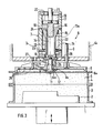
- Figure 3 shows an embodiment of a device solution.
- a model 2 sits on a plate 1 that can be raised and lowered, and a molding box 3 surrounding it, onto which a filling frame 4 is placed.
- Molding box 3 and filling frame 4 are conventionally prior to compression with molding material, for.
- a compression unit Arranged above this molding unit is a compression unit, generally designated 6, which essentially consists of a pressure cylinder 7 and a press plate 8.
- the pressing plate 8 has a peripheral edge 8a drawn downwards and is guided in the stationary part 6a of the compression unit 6 by means of guide rods 9.
- the press plate 8 is further guided at its center on a pin 10 by means of an extension 8b and axially movable on it to a limited extent, a collar 11 arranged at the end of the guide pin 10 serving as the limit stop and having the bottom 12 of a recess 12a in the press plate 8 cooperates.
- the guide pin 10 sits on the piston rod 13 of a drive piston 15, which - like the piston rod 13 - is provided with a cylindrical cavity 14.
- the piston rod 13 and the piston 15 represent the lower limit of a cylinder space 16, which serves as a gas pressure accumulator.
- the upper limit of the volume of the gas pressure accumulator 16 is formed by an actuating piston 17 which projects with an extension 18 into the cylindrical space 14 of the piston 15.
- the actuating piston 17 in turn delimits a pressure chamber 19 which is acted upon hydraulically via an opening 20.
- On the piston 17 also engages a shift rod 21 which passes through the upper cover of the pressure cylinder 7.
- a hydraulic chamber 22 is delimited by the drive piston 15, the piston rod 13, the pressure cylinder 7 and the lower cylinder cover and can be acted upon by hydraulic oil via connections 23 which also serve as a drain.
- the gas pressure accumulator 16 can be connected via connections 24 to one or more further gas pressure accumulators of constant volume can be used to track Lekageluft or as gas volumes that can be switched on and off to change the overall stroke.
- the starting position before a compression stroke is shown in FIG.
- the press plate 8 has previously been placed on the surface of the molding material filling 5 together with the molding box 3 and the filling frame 4 by lifting the model plate 1 into its upper position, being on the guide pin 10 until the upper end face 25 stops centric approach 8b on a stop disc 26 of the piston rod 13 has been performed.
- the drive piston 15 is under a gas prestress in the cylinder space 16 and a hydraulic back pressure in the hydraulic space 22.
- the cross section of the outflow 23 is designed so that the outflow speed is in any case above 10 m / s, so that piston speeds between 2 and 20 m / s can be generated.
- the temporal degradation of the gas pressure in the gas pressure accumulator 16, the effective area of the drive piston 15, the piston mass, the mass of the pressure plate 8, the hydraulic drainage capacity and the mold box area and the height of the compression stroke determine the compression speed and thus the compression result.
- the drive piston 15 Before reaching its end position, the drive piston 15 is braked.
- the piston rod 13 has a conical extension 13a at its upper end.
- a damping ring 7a is in the lower end of the cylinder 7 used, through the opening 7b, the piston rod 13 engages.
- the cross section of the annular space present between the piston rod 13 and the wall of the opening 7b is appreciably larger than the cross section of the outlets 23. As soon as the extension 13a on the piston rod 13 begins to dip into the opening 7b, the cross section thereof narrows increasingly, so that the hydraulic fluid is throttled until the drive piston finally stops.
- the limited displaceability of the press plate 8 on the guide pin 10 leads to a free stroke, which is indicated by 27 in FIG. In this way, fluctuating properties of the molding material and the associated different compression strokes can be automatically compensated. If the working piston 15 has reached its end position, the pressure plate 8 will continue to move due to its inertia up to the end position, which is determined by the fluidity of the molding material particles still present, and will also produce an additional compression effect on the back of the mold.
- the pressure plate 8 Since air can be trapped within the molding column and below the pressure plate 8 at high compression speeds, the pressure plate 8 is provided with slots, holes or nozzles 28 to avoid shape errors.
- the volume of the gas pressure accumulator 16 which also includes the volume of the cylindrical cavity 14, which is provided for reasons of weight saving, can be adjusted via the actuating piston 17. This allows the output pressure and thus the initial acceleration of the working piston to be varied. The final pressure remains constant regardless of the arrangement of the control piston 17 with a constant piston stroke. The timing of the acceleration can, however, as already indicated, vary by connecting external gas storage via the connections 24. These additional gas accumulators are compressed again to their initial pressure when the working piston 15 is reset by means of the hydraulic medium.
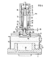
- FIG. 4 an embodiment is shown, the adjustment of the compression stroke, for. B. to adapt to different model geometries.
- a damping sleeve 29 is arranged, which is offset from the pressure cylinder 7 by an annular space 30 on part of its outer surface.
- the damping sleeve 29 is also provided with a plurality of openings 31 which establish the connection between the hydraulic space and the connections 23.
- the damping sleeve 29 can be axially raised and adjusted via a hydraulic system acting on its underside with a connection 32, while the lowering takes place in the hydraulic chamber 22 by the hydraulic fluid.
- the stroke length of the damping sleeve 29 should be approximately 20 to 30% of the compression stroke.
- the molding material is first pre-accelerated below the additional pressure plate mass 35 until finally the remaining lower surface of the pressure plate runs onto the molding material back. The entire molding material mass is then accelerated further.
- the pressure plate 8 and the additional pressure plate mass 35 will each continue to run into their respective end positions independently of one another and depending on the compression of the molding material that is achieved in some areas.
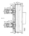
- Figure 6 shows a variant which is particularly suitable for larger molded boxes.
- Two compression units 6, each with a press plate 8 are arranged next to one another on a common carrier 39, each press plate 8 covering approximately half the cross section of the molding box 3 or the filling frame 4.
- the compression stroke of the two compression units 6 can be triggered together, but does not require an exact synchronization movement.
- the switching elements that control the outflow of the hydraulic medium from the hydraulic chamber 22 of the pressure cylinder 7 are expediently arranged in parallel and a pressure compensation line is provided in front of the switching elements.
- the variant according to FIG. 6 can also be modified in such a way that the upper and lower boxes of a complete box shape can be produced in a single work cycle.
- FIG. 5 shows an advantageous exemplary embodiment of the hydraulic control.
- the connections 23 are in a hydraulic high-pressure circuit, the source of which, for. B. a hydraulic pump, designated 41. It is fed from a tank 46. From the high-pressure source 41, the pressure medium passes through a control slide 42 and a check valve 43 into branch lines 44, which lead the pressure medium to the lead both connections 23 of the hydraulic chamber 22.
- the branch lines 44 are connected via a controllable check valve 45 to an outlet tank 47, the outlet 48 of which opens into the tank 46 and which also has a vent 50.
- the check valve 45 is connected to the control slide 42 via a control line 49 and can therefore be acted upon by the hydraulic pump 41. If necessary, the hydraulic chamber 22 can also be connected to the branch lines 44 via a line 51 and a throttle 52 for fine adjustment.
- FIG. 7 finally shows an embodiment of a compression unit 6 with an inductive drive.
- a coil former 54 with a plurality of axially one above the other, Separately excitable and controllable coils 55, 56, 57 and 58 are arranged. Furthermore, a stabilizing and holding coil 59 is present above the coil package 55 to 58.
- the press plate 8 is fastened by means of rods 60 to a coil core 61 which is penetrated by the piston rod 62 with a terminal driver 63 of a log cylinder 64.
- the cylindrical coils 55 to 59 generate a homogeneous, directed electromagnetic force field which automatically aligns the coil core 41 in the rest position, as well as during the movement.
- the compression stroke can be changed in stages by the number of coils 55 to 58 connected.
- the course of acceleration is influenced by the field strength acting on the coil core 61 and, for a given dimension, depends on the current strength within the saturation range of the material of the coil core.
- the compression result can thus be varied not only by varying the compression stroke, but also by changing the current strength of the coils.
- the press plate 8 After compression has taken place, the press plate 8 is brought back into its starting position by means of the remindholzyl Indian 64 and fixed by activating the retention coil 59. Before each compression stroke, the piston rod 62 is extended to the position shown in FIG. 7.
Abstract
Bei einem Verfahren zum Verdichten von Giessereiformstoff, insbesondere Formsand, mittels einer der Formstoffoberfläche unmittelbar aufliegenden Pressplatte, die auf eine Hubgeschwindigkeit bis zu 20 m/s beschleunigt wird, wird eine einwandfreie und gleichmässige Verdichtung über die gesamte Formhöhe dadurch erreicht, dass die Pressplatte in einer Anlaufphase mit bis zu 50% der Gesamthubzeit bis zur maximalen Hubgeschwindigkeit progressiv beschleunigt, in der anschliessenden Hauptphase mit nahezu konstanter Hubgeschwindigkeit bewegt und in der Auslaufphase mit bis zu maximal 30% der Gesamthubzeit degressiv verzögert wird, wobei die Antriebskraft vorzugsweise durch ein hochgespanntes Gasvolumen erzeugt wird, das unter Wirkung einer hydraulischen Gegenlast steht, die für den Verdichtungshub durch schnellen Ablauf des Hydraulikmediums abgebaut wird.In a process for compacting foundry molding material, in particular molding sand, by means of a press plate lying directly on the surface of the molding material, which is accelerated to a lifting speed of up to 20 m / s, a perfect and uniform compression over the entire mold height is achieved in that the press plate in one Start-up phase progressively accelerated with up to 50% of the total stroke time up to the maximum stroke speed, moved with an almost constant stroke speed in the subsequent main phase and declining degressively in the phase-out phase with up to a maximum of 30% of the total stroke time, the driving force preferably being generated by a high-pressure gas volume , which is under the action of a hydraulic counter-load, which is reduced for the compression stroke by rapid drainage of the hydraulic medium.
Description
Die Erfindung betrifft ein Verfahren und eine Vorrichtung zum Verdichten von Gießereiformstoff, insbesondere Formsand, mittels einer der Formstoffoberfläche unmittelbar aufliegenden Preßplatte, die auf eine Hubgeschwindigkeit bis zu 20 m/s beschleunigt wird.The invention relates to a method and a device for compacting foundry molding material, in particular molding sand, by means of a pressing plate lying directly on the molding material surface, which is accelerated to a lifting speed of up to 20 m / s.
Die Technik der Verdichtung von Gießereiformstoff hat in den letzten Jahren eine sprunghafte Entwicklung gemacht, die weitgehend von der Verbesserung der Arbeitsbedingungen, insbesondere der Umweitbedingungen in der Gießerei bestimmt war. So ist das früher übliche Rütteln und Preßrütteln wegen der erheblichen Lärmentwicklung in zunehmendem Maß durch pneumatisch arbeitende Formmaschinen ,beispielsweise Schießmaschinen ersetzt worden, bei denen eine Vorverdichtung durch Abbremsen eines pneumatisch beschleunigten Formstoffvolumens auf dem Modell und der Modellplatte erfolgt. Hierbei ist im allgemeinen ein mechanisches Nachpressen notwendig, um eine ausreichende Formfertigkeit an der Modell kontur zu erreichen.The technique of compaction of foundry molding material has made a leap in recent years, which was largely determined by the improvement of working conditions, especially the environmental conditions in the foundry. For example, because of the considerable noise development, the previously usual shaking and pressing shaking has been increasingly replaced by pneumatically working molding machines, for example shooting machines, in which a pre-compression takes place by braking a pneumatically accelerated volume of molding material on the model and the model plate. Mechanical re-pressing is generally necessary in order to achieve sufficient shape on the model contour.
In neuerer Zeit sind rein pneumatische Verdichtungsverfahren entwickelt worden, bei denen der Formstoff in den Formkasten eingefüllt und anschließend mit einem schlagartigen Gasdruckstoß beaufschlagt wird. Hierfür wird entweder hochgespanntes Druckgas oder ein zur Explosion gebrachtes gasförmiges Brennstoffgemisch verwendet. Mit diesem Verfahren konnten zwar die Formkosten gegenüber den herkömml ichen Verfahren drastisch gesenkt und die Qualität der Form bei einem großen Anteil von Modellen gesteigert werden, doch ergeben sich bei anderen Modellen wieder unerwartete Schwierigkeiten. Mit diesen Verfahren ist es ferner nicht möglich, Gießtrichter oder Gießtümpel direkt einzuformen, da der Formrücken relativ weich bleibt. Bei einigen Gußarten, z. B. Sphäroguß oder Stahlguß, ist ein harter Formrücken und wegen der Belastung beim Gießen eine durchgehend hohe Härte erwünscht, was wiederum dazu zwingt, die Form mechanisch nachzupressen, womit der technische Aufwand zu groß wird. Insgesamt läßt sich für diese Verdichtungsverfahren festellten, daß die Formkosten gegenüber herkömmlichen Verdichtungsverfahren zwar gesenkt werden können, die praktischen Einsatzmöglichkeiten aber begrenzt sind.In recent times, purely pneumatic compression processes have been developed in which the molding material is poured into the molding box and then subjected to an abrupt gas pressure surge. Either high-pressure gas or an explosive gaseous fuel mixture is used for this. With this method, the molding costs could be drastically reduced compared to the conventional methods and the quality of the mold could be increased for a large proportion of models, but unexpected difficulties arise with other models. With these methods it is also not possible to directly mold pouring funnels or pouring basins because the back of the mold remains relatively soft. In some types of casting, e.g. B. nodular cast iron or cast steel, a hard mold back and because of the stress during casting a consistently high hardness is desired, which in turn forces the mold to be mechanically re-pressed, making the technical effort too great. Overall, it can be found for these compression processes that the molding costs can be reduced compared to conventional compression processes, but the practical application possibilities are limited.
Es ist schließlich bereits seit einiger Zeit bekannt, Preßorgane, wie Preßplatten, Preßstempel. Membranen oder dgl. durch Gasdruck zu beaufschlagen, doch haben diese Verfahren bisher keine praktische Bedeutung erlangt, offensichtlich deshalb, weil die Verdichtungswirkung den Bereich bekannter hydraulischer oder pneumatischer Preßverfahren nicht überstieg.After all, it has been known for some time now, press members, such as press plates, press rams. To apply membranes or the like. By gas pressure, but these methods have not gained any practical importance, obviously because the compression effect did not exceed the range of known hydraulic or pneumatic pressing methods.
Es ist schließlich bekannt ("Litejnoe Proizvodstvo in Deutsch"Jg. 1963 H. 3, S. 6 bis 9), eine dem Formstoff frei aufliegende Platte durch Stoßimpuls zu beschleunigen. Dieses sogenannte "Hochgeschwindigkeitspressen" geschieht dadurch, daß ein Schlagkolben in einem Zylinder durch einen gezündeten Exptosivstoff schlagartig beschleunigt wird und seine kinetische Energie beim Aufprall auf die Preßplatte abgibt. Dadurch wird die Preßplatte im Augenblick des Impulses schlagartig auf Maximalgeschwindigkeit beschleunigt und während des Verdichtungshubs durch die innere Reibung der Formstoffpartikel bis zum Stillstand abgebremst. Der zeitliche Verlauf der Verzögerung wird vom Etastizitätsverhalten der Preßplatte und vom Dämpfungsverhalten der Formstoffmasse maßgebl ich beeinflußt. Schwankende Eigenschaften der Formstoffmasse, wie sie in der Praxis üblich sind, sowie unterschiedliche Formstoffhöhen bei verschieden hohen Modellen führen zu unterschiedlicher Verdichtungswirkung, die im übrigen durch überlagerte Stoßwellen gestört wird. Um den Aufbau axial er Stoßwellen zu vermeiden, wird das Antriebsgas über dem Schlagkolben*bereits vor dem Aufschlag auf die Preßplatte durch Auspufföffnungen drucklos entspannt. Es wird ferner in der Literatur darauf hingewiesen, daß es im Bereich des Formrückens zu Abplatzungen und Rissen, sogar zur Kornzerstörung beim Formstoff kommen kann, wei offensichtlich der Formrücken aufgrund der sehr hohen Anfangsbeschleunigung zu stark verdichtet wird, so daß die Form nach dem Entlasten "springt". Dieses Verfahren scheint bisher nur im Labormaßstab durchgeführt worden zu sein. Die Ursachen dürften nicht nur die vorgenannten Nachteile, sondern auch die Tatsache sein, daß bei üblicher Bauhöhe von Formkästen und entsprechend großem Verdichtungshub hochbrisante Explosivstoffe mit entsprechendem Energieinhalt eingesetzt werden müßten, die naturgemäß auch sicherheitstechnische Risiken in sich bergen. Als positiv an diesem dynamischen Pressen muß immerhin die erreichbare Formhärte angesehen werden.Finally, it is known ("Litejnoe Proizvodstvo in German" vol. 1963, H. 3, pp. 6 to 9) to accelerate a plate lying freely on the molding material by a shock pulse. This so-called "high-speed pressing" happens in that a percussion piston in a cylinder is suddenly accelerated by an ignited explosive and its kinetic energy releases on impact on the press plate. As a result, the press plate is suddenly accelerated to maximum speed at the moment of the impulse and braked to a standstill during the compression stroke due to the internal friction of the molding material particles. The time course of the delay is significantly influenced by the elasticity behavior of the press plate and the damping behavior of the molding material. Fluctuating properties of the molding material mass, as are common in practice, as well as different molding material heights for models of different heights lead to different compression effects, which are otherwise disturbed by superimposed shock waves. In order to avoid the build-up of axial shock waves, the drive gas above the percussion piston * is depressurized through exhaust ports before it hits the pressure plate. It is also pointed out in the literature that flaking and cracks, even grain destruction in the molding material, can occur in the area of the back of the mold, since the back of the mold is obviously compressed too much due to the very high initial acceleration, so that the mold after unloading " jumps ". So far, this procedure only seems to have been carried out on a laboratory scale. The causes should not only be the above-mentioned disadvantages, but also the fact that with the usual overall height of mold boxes and a correspondingly large compression stroke, explosive explosives with the corresponding energy content would have to be used, which naturally also entail safety-related risks. After all, the achievable mold hardness must be regarded as positive with this dynamic pressing.
Der Erfindung liegt die Aufgabe zugrunde, das letztgenannte Verfahren dahingehend weiterzuentwickeln, daß eine gleichmäßige und reproduzierbare Verdichtung erreicht wird.The invention has for its object to further develop the latter method in such a way that a uniform and reproducible compression is achieved.
Ausgehend von dem eingangs genannten Verfahren wird diese Aufgabe dadurch gelöst, daß die Preßplatte in einer Anlaufphase mit bis zu 50% der Gesamthubzeit bis zur maximalen Hubgeschwindigkeit progressiv beschleunigt, in der anschließenden Bewegungsphase mit nahezu konstanter Hubgeschwindigkeit bewegt und in der Auslaufphase mit bis zu maximal 30% der Gesamthubzeit degressiv verzögert wird.On the basis of the method mentioned at the outset, this object is achieved in that the pressure plate accelerates progressively up to 50% of the total stroke time up to the maximum lifting speed in the start-up phase, moves with an almost constant lifting speed in the subsequent movement phase and in the run-down phase with up to a maximum of 30 % of the total stroke time is degressively delayed.
Durch das erfindungsgemäße Verfahren ergibt sich zunächst eine weiche Anfangsbeschleunigung der Preßplatte und damit auch des Formstoffs, wodurch eine zu starke Vorverdichtung im Bereich des Formrückens vermieden wird. Die Verdichtung setzt sich nach dieser Anlaufphase in der Hauptphase, in der die maximale Hubgeschwindigkeit erreicht und annähernd konstant beibehalten wird, fort und führt zu einer zunehmenden Verdichtung des Formstoffs über die gesamte Formstoffhöhe. Gegenüber der reinen Stoßverdichtung wird der Vorteil erreicht, daß der Verdichtungsdruck aufgrund des Geschwindigkeitsverlaufs längere Zeit anhält und erst in der Auslaufphase degressiv abgebaut wird. Diese Drucknachführung führt zu einer gleichmäßigen Formhärte über die gesamte Formstoffhöhe. Der Absolutwert der Formhärte läßt sich durch die Einstellung der maximalen Hubgeschwindigkeit vorbestimmen.The method according to the invention initially results in a soft initial acceleration of the press plate and thus also of the molding material, as a result of which excessive compression in the region of the mold back is avoided. After this start-up phase, the compression continues in the main phase, in which the maximum lifting speed is reached and remains almost constant, and leads to an increasing compression of the molding material over the entire molding material height. Compared to pure shock compression, the advantage is achieved that the compression pressure persists for a long time due to the speed curve and is only gradually reduced in the run-down phase. This pressure adjustment leads to a uniform mold hardness over the entire height of the molding material. The absolute value of the mold hardness can be predetermined by setting the maximum lifting speed.
Ein weiterer Lösungsgedanke der Erfindung, der insbesondere in Verbindung mit dem vorgenannten Verfahren, aber auch bei reinen Gasdruck-und Stoßverdichtungsverfahren anwendbar ist, besteht darin, daß die Hubgeschwindigkeit der Preßplatte umgekehrt proportional zur Formstoffhöhe gewählt wird.Another solution of the invention, which can be used in particular in connection with the aforementioned method, but also in the case of pure gas pressure and shock compression methods, is that the lifting speed of the press plate is selected inversely proportional to the height of the molding material.
Es hat sich nämlich gezeigt, daß - anders als an sich zu erwarten - bei einer niedrigen Form eine höhere Hubgeschwindigkeit erforderlich ist, um zu einer gleich guten Verdichtung zu kommen wie bei einer höheren Form.It has been shown that - contrary to what would be expected per se - a higher lifting speed is required for a low shape in order to achieve the same good compression as for a higher shape.
Mit Vorteil beträgt die Hubgeschwindigkeit für Formen bis zu 200 mm Formstoffhöhe zwischen 20 und 12 m/s und für Formen mit 200 bis 400 mm Formstoffhöhe zwischen 12 und 7 m/s und für Formen größer 400 mm zwischen 7 und 2 m/s. Hierdurch lassen sich reproduzierbareThe lifting speed is advantageously between 20 and 12 m / s for molds up to 200 mm high and between 12 and 7 m / s for molds with 200 to 400 mm high and between 7 and 2 m / s for molds larger than 400 mm. This allows reproducible
Verdichtungsgrade in Abhängigkeit von der Formstoffhöhe bzw. der Höhe der herzustellenden Form erhalten.Obtain degrees of compaction depending on the height of the molding material or the height of the mold to be produced.
Gemäß einem bevorzugten Ausführungsbeispiel der Erfindung wird die Preßplatte mittels eines vorgespannten Federantriebs, vorzugsweise mittels einer Gasfeder in Form eines abgeschlossenen,hochgespannten Druckgasvolumens angetrieben. Die von dem Druckgasvolumen erzeugte Antriebskraft wird also unmittelbar auf die Preßplatte übertragen und nicht, wie beim gattungsgemäßen Stand der Technik, zunächst in die Beschleunigung eines Stoßkolbens umgesetzt, der dann auf der Preßplatte abgebremst wird. Durch den erfindungsgemäßen Direktantrieb läßt sich der gewünschte Verlauf der Hubgeschwindigkeit mit reproduzierbaren Verdichtungsergebnissen erreichen.According to a preferred embodiment of the invention, the press plate is driven by means of a prestressed spring drive, preferably by means of a gas spring in the form of a closed, high-tensioned compressed gas volume. The driving force generated by the compressed gas volume is therefore transmitted directly to the press plate and is not, as in the prior art of the generic type, first converted into the acceleration of a push piston, which is then braked on the press plate. With the direct drive according to the invention, the desired course of the lifting speed can be achieved with reproducible compaction results.
Mit Vorteil wird das Druckgas nach dem Entspannen rückkomprimiert,so daß das Antriebsgas stets im Antriebssystem verbleibt. Gegenüber den übl ichen Druckgas-Verdi chtungsverfahren ergibt sich der große wirtschaft-I iche Vorteil, daß nicht bei jedem Verdichtungstakt neue Gasvolumina zur Verfügung gestellt werden müssen, und gegenüber dem Explosionsverfahren entfällt die Notwendigkeit der Abgasbeseitigung und Belüftung.The compressed gas is advantageously recompressed after the expansion, so that the drive gas always remains in the drive system. Compared to the usual compressed gas compression processes, there is the great economic advantage that new gas volumes do not have to be made available with every compression cycle, and the explosion process eliminates the need for exhaust gas removal and ventilation.
Gemäß einem weiteren Merkmal der Erfindung wird die maximale Hubge- schwindigkeit der,Preßplatte durch die Höhe des Gasdrucks eingestellt und der zeitliche Gasdruckabfall und damit der zeitliche Verlauf der Hubgeschwindigkeit der Preßplatte durch hydraulischen Gegendruck gesteuert. Die Höhe des Gasdrucks bestimmt die maximale Hubgeschwindigkeit und wird entsprechend der Formstoffhöhe und/oder der gewünschten Verdichtung eingestellt. Dabei ist die Regel zu befolgen, daß der Gasdruck umso höher liegen muß, je höher die gewünschte Verdichtung sein soll und je niedriger die Formstoffhöhe ist. Der zeitliche Gasdruckabfall, der den Verlauf der Beschleunigung bzw. Verzögerung der Preßplatte bestimmt, läßt sich bei geringstem maschinentechnischem und apparativem Aufwand durch den hydraulischen Gegendruck steuern.According to a further feature of the invention, the maximum Hubge- schwindigk e ith, the press plate is adjusted by the height of the gas pressure and the time the gas pressure drop and thus the timing of the stroke speed of the press plate controlled by hydraulic counter-pressure. The level of the gas pressure determines the maximum lifting speed and is set according to the height of the molding material and / or the desired compression. The rule to be followed is that the higher the desired compression and the lower the height of the molding material, the higher the gas pressure must be. The drop in gas pressure over time, which determines the course of the acceleration or deceleration of the press plate, can be controlled by means of the hydraulic counterpressure with the least expenditure on machinery and equipment.
Eine weitere Steuerungsmöglichkeit für den Geschwindigkeitsverlauf ergibt sich gemäß einem Ausführungsbeispiel dadurch, daß das Druckgasvolumen mit ein oder mehr abgeschlossenen, hochgespannten Gasvolumina in Verbindung steht, die im Verlauf des Druckabfalls zugeschaltet werden. Dadurch läßt sich beispielsweise bei gegebenem kleinem Druckgasvolumen die maximale Hubgeschwindigkeit über einen längeren Zeitraum bzw. einen längeren Hub aufrechterhalten, ohne daß hierfür große Druckspeicher erfordert ich sind. Eine solche Serienschaltung mehrere Gasvolumina ermöglicht eine einfache Steuerung durch Zu- und Abschalten einzelner Gasvolumina.According to one exemplary embodiment, another control option for the speed curve results from the fact that the compressed gas volume is connected to one or more closed, high-tensioned gas volumes which are switched on in the course of the pressure drop. In this way, for example, given a small volume of compressed gas, the maximum stroke speed can be maintained over a longer period of time or a longer stroke without requiring large pressure accumulators. Such a series connection of several gas volumes enables simple control by switching individual gas volumes on and off.
Gemäß einem weiteren Ausführungsbeispiel der Erfindung wird die Preßplatte in der Auslaufphase der Hubbewegung von der Antriebskraft des Gasvolumens abgekoppelt und allein aufgrund des ihrer Massenträgheit entgegenwirkenden Widerstands des Formstoffs bis zu ihrer Endlage verzögert.According to a further exemplary embodiment of the invention, the press plate is decoupled from the driving force of the gas volume in the phase of the lifting movement and decelerated to its end position solely because of the resistance of the molding material to counteract its inertia.
Statt eines pneumatischen Antriebs kann das erfindungsgemäße Verfahren auch dadurch verwirklicht werden , daß die Preßplatte elektromagnetisch angetrieben wird, da mit einem solchen Antrieb gleichfalls schnelle Beschleunigungen und hohe Geschwindigkeiten möglich sind.Instead of a pneumatic drive, the method according to the invention can also be implemented in that the press plate is driven electromagnetically, since fast accelerations and high speeds are also possible with such a drive.
Zur Steuerung des Geschwindigkeitsverlaufs können entlang des Hubwegs der Preßplatte Magnetfelder steuerbarer Intensität zur Wirkung gebracht werden.To control the speed curve, magnetic fields of controllable intensity can be brought into effect along the stroke of the press plate.
Zur Durchführung des Verfahrens geht die Erfindung aus von einer Vorrichtung, die in herkömmlicher Weise aus einer Modellplatte, einem den Formstoff aufnehmenden Formkasten mi t Fül rahmen und ei ner darüber angeordneten Preßplatte mit einem Antrieb besteht, unter dessen Wirkung die Preßplatte in den Füllrahmen unter Verdichtung des Formstoffs eintaucht. Solche bekannten Vorrichtungen werden beispielsweise zum statischen Pressen mit hydraul ischem Antrieb verwendet.To carry out the method, the invention is based on a device which, in a conventional manner, consists of a model plate, a the molding material-receiving mold box with filling frame and a press plate arranged above it with a drive, under whose effect the press plate is immersed in the filling frame with compression of the molding material. Such known devices are used, for example, for static pressing with a hydraulic drive.
Eine solche Vorrichtung zeichnet sich erfindungsgemäß dadurch aus, daß als Antrieb ein Speicher mit hochgespanntem Druckgas dient, dessen eine Begrenzung von einem Antriebskolben gebildet ist, an dem die Preßplatte angeschlossen ist, und daß der Antriebskolben an seiner gegenüberliegenden Seite unter Wirkung einer hydraulischen Gegenlast steht. Die hydraulische Gegenlast ist durch die Abflußgeschwindigkeit des Hydraul ikmediums entsprechend dem gewünschten Verlauf der Hubgeschwindigkeit der Preßplatte abbaubar. Dabei sollte die Abflußgeschwindigkeit im Bereich > 10 m/s liegen, um die maximale Hubgeschwindigkeit von bis zu 20 m/s zu erreichen. Gemäß einem Ausführungsbeispiel ist die Abflußgeschwindigkeit des Hydraulikmediums steuerbar.According to the invention, such a device is characterized in that a storage device with high-pressure compressed gas serves as the drive, the boundary of which is formed by a drive piston to which the press plate is connected, and in that the drive piston is on its opposite side under the action of a hydraulic counter-load. The hydraulic counter-load can be reduced by the outflow speed of the hydraulic medium corresponding to the desired course of the lifting speed of the press plate. The discharge speed should be in the range> 10 m / s in order to reach the maximum lifting speed of up to 20 m / s. According to one embodiment, the outflow speed of the hydraulic medium is controllable.
Gemäß einer weiteren Ausführungsform ist das Volumen des Druckgasspeichers voreinstellbar , so daß der Gesamthub und die Druckhöhe an die Formstoffhöhe angepaßt werden können. Der Druckverlauf über den Gesamthub läßt sich ferner dadurch beeinflussen, daß der Druckgasspeicher mit wenigstens einem zuschaltbaren externen Druckgasspeicher verbunden ist.According to a further embodiment, the volume of the compressed gas store can be preset so that the total stroke and the pressure height can be adapted to the height of the molding material. The pressure profile over the entire stroke can also be influenced in that the compressed gas storage device is connected to at least one switchable external compressed gas storage device.
Weitere vorteilhafte Ausführungsmerkmale des Antriebssystems und der Steuerung ergeben sich aus den Ansprüchen 15 bis 17 und 20 bis 27.Further advantageous design features of the drive system and the control result from
Gemäß einem weiteren vorteilhaften Ausführungsbeispiel ist die Preßplatte an dem Antriebskolben begrenzt axial verschieblich geführt. Dies gibt die Möglichkeit, die Preßplatte bei Entspannung des Gasvolumens direkt anzutreiben und nach erfolgter Entspannung aufgrund ihrer kinetischen Energie weiterzubewegen, um die Restverdichtung in der Auslaufphase zu bewirken.According to a further advantageous embodiment, the pressure plate is guided axially displaceably on the drive piston. This gives the possibility to directly drive the pressure plate when the gas volume is released and to move it further after relaxation due to its kinetic energy in order to effect the residual compression in the run-down phase.
In weiterer vorteilhafter Ausführung ist die Preßplatte entsprechend der Modellkontur profiliert. Sie kann insbesondere im Bereich tiefer Modellkonturen einzelne Erhöhungen aufweisen, um über die gesamte Formstoffhöhe unabhängig von der jeweiligen Modellhöhe eine gleichmäßige Verdichtung zu erreichen.In a further advantageous embodiment, the press plate is profiled in accordance with the model contour. In particular in the area of deep model contours, it can have individual elevations in order to achieve uniform compression over the entire height of the molding material, regardless of the respective model height.
Mit Vorzug wird die Masse der Preßplatte umgekehrt proportional der Formstoffhöhe bzw. der Formstoffmasse gewählt. Für die durch Aufprallverzögerung des Formstoffs über der Modellkontur stattfindende Formstoffverdichtung ist die zu verzögernde Masse aus Formstoff und Pressplatte mitentscheidend. Durch die umgekehrte Proportionalität der Masse wirkt bei geringer Formstoffhöhe die anteilig höhere Plattenmasse ersatzweise anstelle der geringeren Formstoffmasse und führt zusammen mit der angestrebt höheren Hubgeschwindigkeit bei geringen Formstoffhöhen zu einem vergleichbar höherem Verdichtungsimpuls mit entsprechend hoher Verdichtungsintensität.The mass of the press plate is preferably selected inversely proportional to the height of the molding material or the molding material mass. For the compression of the molding material due to the impact of the molding material above the model contour, the mass of molding material and press plate to be decelerated is also decisive. Due to the inverse proportionality of the mass, the proportionally higher plate mass acts instead of the lower molding material mass at a low molding material height and, together with the desired higher lifting speed at low molding material heights, leads to a comparatively higher compression impulse with a correspondingly high compression intensity.
Im übrigen ist es von Vorteil, wenn die Preßplattenmasse und die Formstoffmasse in einem Verhältnis zwischen 1 : 1 und 1 : 10 stehen. Auch durch Wahl der Preßplattenmasse lassen sich die Hubgeschwindigkeit und der Geschwindigkeitsverlauf in einfacher Weise beeinflussen. Bei gleicher Antriebskraft wird mit einer kleineren Preßplattenmasse eine kürzere Anlaufphase bei höherer Hubgeschwindigkeit erreicht.For the rest, it is advantageous if the pressure plate mass and the molding material mass are in a ratio between 1: 1 and 1:10. The lifting speed and the speed curve can also be influenced in a simple manner by selecting the pressure plate mass. With the same driving force, a shorter press-on phase with a higher lifting speed is achieved with a smaller press plate mass.
Wird dieAntriebskraft zur Durchführung des erfindungsgemäßen Verfahrens auf elektromagnetischem Wege erzeugt, so zeichnet sich erfindungsgemäß eine zur Durchführung des Verfahrens geeignete Vorrichtung dadurch aus, daß der Antrieb aus mehreren axial hintereinander angeordneten elektromagnetischen Spulen besteht und die Preßplatte einen in diesen eintauchenden Spulenkörper aufweist. Damit läßt sich die Preßplatte entsprechend dem gewünschten Geschwindigkeitsverlauf beschleunigen.If the driving force for carrying out the method according to the invention is generated by electromagnetic means, a device suitable for carrying out the method is characterized in that the drive consists of a plurality of electromagnetic coils arranged axially one behind the other and the pressing plate has a coil body immersed in it. The press plate can thus be accelerated in accordance with the desired speed profile.
Gegebenenfalls kann die Stromstärke jeder Spule steuerbar seln, um die Höhe der Hubgeschwindigkeit und ihren zeitlichen Verlauf zu beeinflussen. Dies läßt sich zusätzlich durch getrenntes Zu- und Abschalten der Spulen erreichen.If necessary, the current strength of each coil can be controlled in order to influence the height of the lifting speed and its course over time. This can also be achieved by switching the coils on and off separately.
Mit Vorteil ist der Spulenkörper freifliegend innerhalb der Spulen angeordnet und in der angehobenen Ausgangslage von einer Zentrier- und Rückhaltespule gehal ten.Advantageously, the bobbin is arranged free-floating within the coils and held in the raised starting position by a centering and retention coil.
Nachstehend ist die Erfindung anhand von in der Zeichnung dargestellten Ausführungsbeispielen beschrieben.The invention is described below with reference to exemplary embodiments shown in the drawing.
In der Zeichnung zeigen:
Figur 1 ein Hub-Zeitdiagramm für das Verdichtungsverfahren gemäß dem Stand der Technik und gemäß der Erfindung;Figur 2 ein aus demDiagramm gemäß Figur 1 abgeleitetes Diagramm Hubgeschwindigkeit/Hubzeit;Figur 3 einen schematischen Schnitt durch eine Ausführungsform der Vorrichtung zur Durchführung des Verfahrens;Figur 4 einen der Figur 3 ähnlichen Schnitt einer weiteren Ausführungsform;Figur 5 ein Schaltbild für die hydraulische Steuerung;Figur 6 einen der Figur 3 und 4 ähnlichen Schnitt einer weiteren Ausführungsform der Vorrichtung undFigur 7 einen der Figur 3 und 4 ähnlichen Schnitt einer Ausführungsform mit elektromagnetischem Antrieb.
- Figure 1 is a stroke timing diagram for the compression method according to the prior art and according to the invention;
- Figure 2 is a diagram derived from the diagram of Figure 1 lifting speed / lifting time;
- Figure 3 shows a schematic section through an embodiment of the device for performing the method;
- Figure 4 shows a section similar to Figure 3 of another embodiment;
- Figure 5 is a circuit diagram for the hydraulic control;
- 6 shows a section similar to FIGS. 3 and 4 of a further embodiment of the device and
- 7 shows a section similar to FIGS. 3 and 4 of an embodiment with an electromagnetic drive.
In dem Hub/Zeitdiagramm der Figur 1 ist mit der Kurve a der Verlauf einer durchStoß beschleunigten Bewegung gemäß dem Stand der Technik; das als sogenanntes"Hochgeschwindigkeitspressen" bekannt ist, wiedergegeben. Aus dem Kurvenverlauf läßt sich erkennen, daß der Hub pro Zeiteinheit zwar schnell anwächst, über den Gesamtverlauf jedoch stetig abnimmt. Die Kurve b gibt den Verlauf beim erfindungsgemäßen Verfahren wieder, indem die Pressplatte zunächst langsam anläuft und in der Hauptphase mit einer annähernd gleichbleibenden Geschwindigkeit bewegt wird, um schließlich in der Auslaufphase degressiv abgebremst zu werden. Die Anlaufphase nimmt dabei etwa 10 bis 50% des Gesamthubzeit ein, während die Auslaufphase bis maximal 30%, vorzugsweise zwischen 10 und 20% der Gesamthubzeit beträgtIn the stroke / time diagram of FIG. 1, curve a shows the course of a movement accelerated by impact according to the prior art; which is known as so-called "high speed pressing" reproduced. From the course of the curve it can be seen that the stroke per unit of time increases rapidly, but decreases steadily over the entire course. Curve b shows the course in the method according to the invention in that the press plate initially starts up slowly and is moved at an approximately constant speed in the main phase, in order to finally be decelerated in the deceleration phase. The start-up phase takes up about 10 to 50% of the total stroke time, while the run-down phase is up to a maximum of 30%, preferably between 10 and 20% of the total stroke time
Das Diagramm gemäß Figur 2 gibt Auskunft über den bei dem bekannten und dem erfindungsgemäßen Verfahren auftretenden Verlauf der Geschwindigkeit der Preßplatte. Bei dem bekannten Verfahren gemäß Kurve a nimmt die Hubgeschwindigkeit im Augenblick des Aufpralls des Stoßkolbens ihren Höchstwert an und fällt danach kontinuierlich über einen größeren Bereich linear und in der Auslaufphase degressiv ab. Bei dem erfindungsgemäßen Verfahren gemäß Kuve b nimmt die Geschwindigkeit demgegenüber langsam und progressiv zu bis zum Erreichen der maximalen Hubgeschwindigkeit, die dann über einen größeren Bereich, die Hauptphase, annähernd konstant bleibt, um schließlich relativ schlagartig in eine degressive Verzögerung in der Auslaufphase überzugehen. Dabei wird die maximale Hubgeschwindigkeit an die Formstoffhöhe und den gewünschten Verdichtungsgrad angepaßt.The diagram according to FIG. 2 provides information about the course of the speed of the press plate which occurs in the known and the method according to the invention. In the known method according to curve a, the stroke speed peaks at the moment of the impact of the impact piston and thereafter decreases linearly over a larger area and decreases degressively in the run-down phase. In the method according to the invention according to curve b, on the other hand, the speed increases slowly and progressively until the maximum lifting speed is reached, which then remains approximately constant over a larger area, the main phase, in order finally to change relatively suddenly into a declining deceleration in the phase-out phase. The maximum lifting speed is adapted to the height of the molding material and the desired degree of compaction.
Figur 3 zeigt eine Ausführungsform einer vorrichtungstechnischen Lösung. Auf einer heb- und senkbaren Platte 1 sitzt ein Modell 2 und ein dieses umgebender Formkasten 3, auf den ein Füllrahmen 4 aufgesetzt ist. Formkasten 3 und Füllrahmen 4 werden in herkömmlicher Weise vor dem Verdichten mit Formstoff, z. B. bentonitgebundenem Formsand 5 gefüllt.Figure 3 shows an embodiment of a device solution. A
Oberhalb dieser Formeinheit ist eine insgesamt mit 6 bezeichnete Verdichtungseinheit angeordnet, die im wesentlichen aus einem Druckzylinder 7 und einer Preßplatte 8 besteht. Die Preßplatte 8 weist beim wiedergegebenen Ausführungsbeispiel einen nach unten gezogenen Umfangsrand 8a auf und ist mittels Führungsstangen 9 in dem ortsfesten Teil 6a der Verdichtungseinheit 6 geführt. Die Preßplatte 8 ist weiterhin mittels eines Ansatzes 8b in ihrem Zentrum an einem Zapfen 10 geführt und auf diesem begrenzt axial beweglich, wobei als Begrenzungsanschlag ein am Ende des Führungszapfens 10 angeordneter Bund 11 dient, der mit dem Boden 12 einer Ausnehmung 12a in der Preßplatte 8 zusammenwirkt.Arranged above this molding unit is a compression unit, generally designated 6, which essentially consists of a
Der Führungszapfen 10 sitzt an der Kolbenstange 13 eines Antriebskolbens 15, der - ebenso wie die Kolbenstange 13 - mit einem zylindrischen Hohlraum 14 versehen ist. Die Kolbenstange 13 und der Kolben 15 stellen die untere Begrenzung eines Zylinderraums 16 dar, der als Gasdruckspeicher dient. Die obere Begrenzung des Volumens des Gasdruckspeichers 16 ist durch einen Stellkolben 17 gebildet, der mit einem Ansatz 18 in den zylindrischen Raum 14 des Kolbens 15 hineinragt. Der Stellkolben 17 begrenzt wiederum einen Druckraum 19, der über eine Öffnung 20 hydraulisch beaufschlagt ist. An dem Kolben 17 greift ferner eine Schaltstange 21 an, die den oberen Deckel des Druckzylinders 7 durchgreift.The
Von dem Antriebskolben 15, der Kolbenstange 13, dem Druckzylinder 7 und dem unteren Zylinderdeckel wird ein Hydraulikraum 22 begrenzt, der über Anschlüsse 23, die ferner als Abfluß dienen, mit Hydrauliköl beaufschlagt werden kann.A
Der Gasdruckspeicher 16 kann über Anschlüsse 24 an ein oder mehr weitere Gasdruckspeicher konstanten Volumens angeschlossen sein, die zum Nachführen von Lekageluft oder aber al s zu- und abschaltbare Gasvolumina zur Veränderung des Gesamthubs dienen können. Oberhalb des Antriebsko Ibens 15 steht ein Gasdruck zwischen 50 und 200bar an, während der Hydraulikraum 22 an ein Hydrauliksystem mit Arbeitsdrücken zwischen 100 und 350 bar je nach Verhältnis der Kolbenflächen angeschlossen ist.The
In Figur 3 ist die Ausgangslage vor einem Verdichtungshub wiedergegeben. Die Preßplatte 8 ist zuvor unter Auflage auf der Oberfläche der Formstoff-Füllung 5 zusammen mit dem Formkasten 3 und dem Füllrahmen 4 durch Anheben der Modellplatte 1 in ihre obere Lage verbracht worden, wobei sie auf dem Führungszapfen 10 bis zum Anschlag der oberen Stirnseite 25 ihres zentrischen Ansatzes 8b an einer Anschlagscheibe 26 der Kolbenstange 13 geführt worden ist. Der Antriebskolben 15 steht unter einer Gasvorspannung im Zylinderraum 16 und einem hydraulischen Gegendruck im Hydraul ikraum 22.The starting position before a compression stroke is shown in FIG. The
Bei Freigabe der im Hydraulikraum 22 eingespannten Hydrauliksäule werden der Arbeitskolben 15 mit der Kolbenstange 13 sowie die Preßplatte 8 und schließlich auch die Formstoff-Fül lung 5 in Richtung auf das Modell 2 beschleunigt. Der Querschnitt des Abflusses 23 wird so ausgelegt, daß die Abflußgeschwindigkeit in jedem Fall über 10 m/s liegt, so daß Kolbengeschwindigkeiten zwischen 2 und 20 m/s erzeugt werden können. Der zeitliche Abbau des Gasdrucks im Gasdruckspeicher 16, die wirksame Fläche des Antriebskolbens 15, die Kolbenmasse, die Masse der Preßplatte 8, die Hydraulik-Abflußleistung sowie die Formkastenfläche und die Höhe des Verdichtungshubs bestimmen die Verdichtungsgeschwindigkeit und damit das Verdichtungsergebnis. Mit mehreren Abflüssen 23 in der Größenordnung bis ca. 100mm lassen sich kurzzeitig Abflußgeschwindigkeiten bis zu 40 m/s erreichen. Weitere Details dieser Steuerung sind später mit Bezug auf Figur 5 beschrieben.When the hydraulic column clamped in the
Vor Erreichen seiner Endlage wird der Antriebskolben 15 abgebremst. Hierzu weist die Kolbenstange 13 an ihrem oberen Ende eine konische Erweiterung 13a auf. Ferner ist in das untere Ende des Zylinders 7 ein Dämpfungsring 7a eingesetzt, durch dessen Öffnung 7b die Kolbenstange 13 hindurchgreift.Before reaching its end position, the
Der Querschnitt des zwischen der Kolbenstange 13 und der Wandung der Öffnung 7b vorhandenen Ringraums ist nennenswert größer als der Querschnitt der Abflüsse 23. Sobald die Erweiterung 13a an der Kolbenstange 13 in die Öffnung 7b einzutauchen beginnt, verengt sich deren Querschnitt zunehmend, so daß die Hydraulikflüssigkeit gedrosselt wird, bis schließlich der Antriebskolben zum Stehen kommt.The cross section of the annular space present between the
Die begrenzte Verschiebl ichkeit der Preßpl atte 8 auf dem Führungszapfen 10 führt zu einem Freihub, der in Figur 3 mit 27 angedeutet ist. Damit können schwankende Eigenschaften des Formstoffs und damit verbundene unterschiedl iche Verdichtungshübe automatisch ausgeglichen werden. Hat nämlich der Arbeitskolben 15 seine Endlage erreicht, so wird die Preßplatte 8 sich aufgrund ihrer Massenträgheit bis zur Endlage, die von dem noch vorhandenen Fließvermögen der Formstoffpartikel bestimmt wird weiterbewegen und darüber hinaus auf dem Formrücken eine zusätzliche Verdichtungswirkung erzeugen.The limited displaceability of the
Da es bei hohen Verdichtungsgeschwindigkeiten zu Lufteinschlüssen innerhalb der Formstoffsäule und unterhal b der Preßplatte 8 kommen kann, ist die Preßplatte 8 zur Vermeidung von Formfehlern mit Schlitzen, Löchern oder Düsen 28 versehen.Since air can be trapped within the molding column and below the
Das Volumen des Gasdruckspeichers 16, das auch das Volumen des zylindrischen Hohlraums 14, der aus Gründen der Gewichtsersparnis vorgesehen ist, einschließt, kann über den Stellkolben 17 eingestellt werden. Dadurch läßt sich der Ausgangsdruck und damit die Anfangsbeschleunigung des Arbeitskolbens variieren. Der Enddruck bleibt unabhängig von der Anordnung des Stellkolbens 17 bei konstantem Kolbenhub gleichfalls konstant. Der zeitliche Ablauf der Beschleunigung läßt sich aber, wie bereits angedeutet, durch Zuschal tung externer Gasspeicher über die Anschlüsse 24 variieren. Auch diese zusätzlichen Gasspeicher werden bei der Rückstellung des Arbeitskolbens 15 mittels des Hydraulikmediums wieder auf ihren Ausgangsdruck zurückkompri miert.The volume of the
In Figur 4 ist eine Ausführungsform gezeigt, die eine Einstellung des Verdichtungshubs, z. B. zur Anpassung an unterschiedliche Modellgeometrien ermöglicht. Im unteren Bereich des Hydraufikraums 22 ist statt des ortsfesten Dämpfungsrings 7a der Figur 3 eine Dämpfungshülse 29 angeordnet, die auf einem Teil ihrer Mantelfläche vom Druckzylinder 7 durch einen Ringraum 30 abgesetzt ist. Die Dämpfungshülse 29 ist ferner mit mehreren Durchbrüchen 31 versehen, die die Verbindung zwischen dem Hydraulikraum und den Anschlüssen 23 herstellen. Die Dämpfungshülse 29 kann über eine auf ihre Unterseite wirkende Hydraulik mit einem Anschluß 32 axial angehoben und eingestellt werden, während das Absenken durch die Hydraulikflüssigkeit im Hydraulikraum 22 geschieht. Die Hublänge der Dämpfungshülse 29 sollte dabei ca. 20 bis 30% des Verdichtungshubs betragen. Statt dieser Variation der Dämpfungslage des Antriebskolbens 15 ist es auch möglich, die Hublage der Modellplatte 1 mittels eines entsprechenden Hubaggregates einzustellen, so daß ein beliebiger Teil des in Figur 3 mit 27 bezeichneten Freihubs als freier Vorlauf 33 der Preßplatte 8 zur Verfügung steht, so daß sich bei vollem Hub des Arbeitskolbens 15 ein geringerer Hub der Preßplatte 8 ergibt. Vor allem bei dieser Ausführungsform kann es vorteilhaft sein, an der Stirnseite 25 des zentrischen Ansatzes 8b der Preßplatte 8 einen elastischen Aufschlagring 34 einzulegen, um Aufschlaggeräusche zu vermeiden.In Figure 4, an embodiment is shown, the adjustment of the compression stroke, for. B. to adapt to different model geometries. In the lower area of the
Bei ausgefallenen Modellen mit star k unterschiedlicher Modellhöhe sind bereichsweise unterschiedliche Verdichtungshübe notwendig. Dies läßt sich durch zusätzliche Massen an der Preßplatte 8 verwirklichen, die an die Modellkontur angepaßt sind. Dabei ist es besonders vorteilhaft, auch diese zusätzlichen Massen an der Preßplatte 8 axial beweglich zu führen, um ein selbsttätiges Nachlaufen dieser Massen bei formstoffbedingten Schwankungen des Verdichtungshubs zu ermöglichen. In Figur 4 ist eine solche zusätzliche Verdichtungsmasse 35 wiedergegeben, die für ein großes Ballenmodell vorgesehen ist, dessen Grundfläche 36 bis unterhal b der Trennebene 37 reicht. Die zusätzliche Preßplattenmasse 35 ist über Stehbolzen 38 an der Preßplatte 8 geführt. In der Ausgangslage ist aufgrund der Hubbewegung der Modellplatte 1 die zusätzliche Preßplattenmasse 35 zur Anlage an die Unterseite der Preßplatte 8 gebracht worden. Beim nachfolgenden Verdichtungshub wird zunächst der Formstoff unterhalb der zusätzlichen Preßplattenmasse 35 vorbeschleunigt, bis schließlich die restl iche Unterfläche der Preßplatte auf den Formstoffrücken aufläuft. Danach wird die gesamte Formstoffmasse weiterbeschleunigt. Hat der Antriebskolben 15 seine Endlage erreicht, werden die Preßplatte 8 und die zusätzliche Preßplattenmasse 35 infolge Massenträgheit jeweils unabhängig voneinander und abhängig von der bereichsweise erreichten Verdichtung des Formstoffs in ihre jeweilige Endlage weiterlaufen.For unusual models with strong k different model heights, different compression strokes are necessary in some areas. This can be achieved by additional masses on the
Figur 6 zeigt eine Variante, die insbesondere für größere Formkästen geeignet ist. Hierbei sind auf einem gemeinsamen Träger 39 zwei Verdichtungsaggregate 6 mit je einerPreßplatte 8 nebeneinander angeordnet, wobei jede Preßplatte 8 etwa den halben Querschnitt des Formkastens 3 bzw. des Füllrahmens 4 überdeckt. Der Verdichtungshub der beiden Verdichtungsaggregate 6 kann gemeinsam ausgelöst werden, erfordert jedoch keine exakte Gleichlaufbewegung. Zweckmäßig sind jedoch die Schaltorgane, die den Abfluß des Hydraul ikmediums aus dem Hydraul ikraum 22 des Druckzylinders 7 steuern, parallel angeordnet und vor den Schaltorganen eine Druckausgleichsleitung vorgesehen. Die Variante gemäß Figur 6 kann auch in der Weise abgewandelt werden, daß zugleich Ober- und Unterkasten einer kompletten Kastenform in einem einzigen Arbeitstakt hergestellt werden können.Figure 6 shows a variant which is particularly suitable for larger molded boxes. Two
In Figur 5 ist ein vorteilhaftes Ausführungsbeispiel der hydraulischen Steuerung wiedergegeben. Die Anschlüsse 23 liegen in einem Hydraul ik-Hochdruckkreislauf, dessen Quelle, z. B. eine Hydraulikpumpe, mit 41 bezeichnet ist. Sie wird aus einem Tank 46 gespeist. Von der Hochdruckquelle 41 gelangt das Druckmittel über einen Steuerschieber 42 und ein Rückschlagventil 43 in Zweigleitungen 44, die das Druckmittel zu den beiden Anschlüssen 23 des Hydraulikraums 22 führen. Die Zweigleitungen 44 sind über ein aufsteuerbares Rückschlagventil 45 an einen Ablauftank 47 angeschlossen, dessen Abfluß 48 in den Tank 46 mündet und der ferner eine Entlüftung 50 aufweist. Das Rückschlagventil 45 liegt über eine Steuerleitung 49 am Steuerschieber 42 und kann somit von der Hydraulikpumpe 41 beaufschlagt werden. Gegebenenfalls kann der Hydraulikraum 22 noch über eine Leitung 51 und eine Drossel 52 zur Feineinstellung mit den Zweigleitungen 44 verbunden sein.FIG. 5 shows an advantageous exemplary embodiment of the hydraulic control. The
In der Position "B" des Steuerschiebers 42 wird der Hydraulikraum 22 von der Hydraulikpumpe 41 beaufschlagt, so daß der Arbeitskolben 15 das Gasvolumen im Speicher 16 auf den gewünschten Enddruck bringt. Das aufsteuerbare Rückschlagventi 1 45 befindet sich dabei in der Schließstellung. Die Preßplatte 8 ist durch Nachführen der Modellplatte 1 mit Formkasten 3 und Füllrahmen 4 in ihre obere Ausgangslage bewegt worden.In position "B" of the
Durch Umschalten des Steuerschiebers 42 in die Position "A" wird der Hydraulikraum 22 über das Rückschlagventil 43 gegenüber der Hydraulikpumpe 41 abgeschlossen, während zugleich die Pumpe über die Steuerleitung 49 das Rückschlagventil 45 öffnet. Die Hydraulikflüssigkeit kann über die Anschlüsse 23, die Zweigleitungen 44 und das offene Rückschlagventi I 45 schlagartig in den Ablauftank 47 abfließen, dessen Volumen groß genug ist, um die gesamte Hydraulikmenge des Systems aufzunehmen und den Druck schlagartig abzubauen. Dabei bewegen sich der Arbeitskolben 15 und die Preßplatte 8 mit dem gewünschten Geschwindigkeitsverlauf nach unten, um die Formstoff-Füllung 5 zu verdichten.By switching the
Figur 7 zeigt schließlich eine Ausführungsform eines Verdichtungsaggregates 6 mit einem induktiven Antrieb. In einem Maschinengestell 53 ist ein Spulenkörper 54 mit mehreren axial übereinander angeordneten, getrennt erregbaren und steuerbaren Spulen 55, 56, 57 und 58 angeordnet. Ferner ist eine Stabilisierungs- und Haltespule 59 oberhalb des Spulenpakets 55 bis 58 vorhanden. Die Preßplatte 8 ist mittels Stangen 60 an einem Spulenkern 61 befestigt, der von der Kolbenstange 62 mit endständigem Mitnehmer 63 eines Rückholzylinders 64 durchgriffen ist.FIG. 7 finally shows an embodiment of a
Die zylindrischen Spulen 55 bis 59 erzeugen ein homogenes, gerichtetes elektromagnetisches Kraftfeld, das den Spulenkern 41 in der Ruhelage, wie auch bei der Bewegung selbsttätig axial ausrichtet. Der Verdichtungshub läßt sich durch die Anzahl der zugeschalteten Spulen 55 bi s 58 in Stufen ändern. Der Beschleunigungsverlauf wird durch die auf den Spulenkern 61 wirkende Feldstärke beeinflußt und hängt bei gegebener Dimensionierung innerhalb des Sättigungsbereichs des Materials des Spulenkerns von der Stromstärke ab. Das Verdichtungsergebnis läßt sich somit nicht nur durch die Variation des Verdichtungshubs, sondern auch durch Änderung der Stromstärke der Spulen variieren.The cylindrical coils 55 to 59 generate a homogeneous, directed electromagnetic force field which automatically aligns the
Nach erfolgter Verdichtung wird die Preßplatte 8 mittels des Rückholzyl inders 64 wieder in ihre Ausgangslage gebracht und durch Aktivieren der Rückhaltespule 59 fixiert. Vor jedem Verdichtungshub wird die Kolbenstange 62 wieder in ihre in Figur 7 wiedergegebene Lage ausgefahren .After compression has taken place, the
Claims (37)
dadurch gekennzeichnet,
daß die Preßplatte in einer Anlaufphase mit bis zu 50% der Gesamthubzeit bis zur maximalen Hubgeschwindigkeit progressiv beschleunigt , in der anschließenden Bewegungsphase mit nahezu konstanter Hubgeschwin digkeit bewegt und in der Auslaufphase mit bis zu maximal 30% der Gesamthubzeit degressiv verzögert wird.1. Process for compacting foundry molding material, in particular molding sand, by means of a press plate lying directly on the molding material surface, which is accelerated to a lifting speed of up to 20 m / s,
characterized,
that the press plate in a start-up phase with up to 50% of the total stroke time progressively accelerates to the maximum stroke speed, moves in the subsequent movement phase with an almost constant stroke speed and in the run-down phase is degressively delayed with up to a maximum of 30% of the total stroke time.
Applications Claiming Priority (2)
| Application Number | Priority Date | Filing Date | Title |
|---|---|---|---|
| DE3406466A DE3406466A1 (en) | 1984-02-23 | 1984-02-23 | METHOD AND DEVICE FOR COMPRESSING FOUNDRY MOLD |
| DE3406466 | 1984-02-23 |
Publications (3)
| Publication Number | Publication Date |
|---|---|
| EP0152928A2 true EP0152928A2 (en) | 1985-08-28 |
| EP0152928A3 EP0152928A3 (en) | 1986-06-04 |
| EP0152928B1 EP0152928B1 (en) | 1988-01-20 |
Family
ID=6228536
Family Applications (1)
| Application Number | Title | Priority Date | Filing Date |
|---|---|---|---|
| EP85101687A Expired EP0152928B1 (en) | 1984-02-23 | 1985-02-15 | Method of and installation for compacting foundry mould material |
Country Status (5)
| Country | Link |
|---|---|
| US (1) | US4617978A (en) |
| EP (1) | EP0152928B1 (en) |
| JP (1) | JPH078411B2 (en) |
| DD (1) | DD235197A5 (en) |
| DE (2) | DE3406466A1 (en) |
Cited By (1)
| Publication number | Priority date | Publication date | Assignee | Title |
|---|---|---|---|---|
| GB2199523A (en) * | 1986-11-25 | 1988-07-13 | Doyle Ltd C F | Compacting a moulding mixture by a pressurised gas wave |
Families Citing this family (7)
| Publication number | Priority date | Publication date | Assignee | Title |
|---|---|---|---|---|
| CH672270A5 (en) * | 1986-12-17 | 1989-11-15 | Fischer Ag Georg | |
| DE3719846A1 (en) * | 1987-06-13 | 1988-12-22 | Badische Maschf Gmbh | Method and apparatus for compacting moulding material in foundry moulding machines |
| DE3740185A1 (en) * | 1987-06-13 | 1989-06-08 | Badische Maschf Gmbh | METHOD AND DEVICE FOR COMPRESSING MOLDING MATERIAL IN FOUNDRY MOLDING MACHINES |
| US5070928A (en) * | 1990-02-28 | 1991-12-10 | General Motors Corporation | Forming press with quick-change tool-to-bolster locking mechanism |
| CH686412A5 (en) * | 1992-03-10 | 1996-03-29 | Fischer Georg Giessereianlagen | A method of compacting molding sand for molds. |
| US5535809A (en) * | 1993-11-24 | 1996-07-16 | Grand Haven Brass Foundry | Method and apparatus for packing a granular material for foundry use |
| AU2000232748A1 (en) * | 2000-03-20 | 2001-10-03 | Georg Fischer Disa A/S | Method and apparatus for producing two-part moulds |
Citations (5)
| Publication number | Priority date | Publication date | Assignee | Title |
|---|---|---|---|---|
| DE7602966U1 (en) * | 1976-02-03 | 1976-06-24 | Badische Maschinenfabrik Gmbh, 7500 Karlsruhe | FOUNDRY MOLDING MACHINE FOR BOX MOLDS |
| DE2844464B1 (en) * | 1978-10-12 | 1980-04-24 | Eugen Dipl-Ing Buehler | Method and device for compacting casting molds |
| GB2043507A (en) * | 1979-03-08 | 1980-10-08 | Sintokogio Ltd | Moulding apparatus |
| JPS55149749A (en) * | 1979-05-11 | 1980-11-21 | Sintokogio Ltd | Mold molding method |
| DE3002702A1 (en) * | 1980-01-25 | 1981-07-30 | Alfelder Maschinen- und Modell-Fabrik Künkel, Wagner & Co KG, 3220 Alfeld | Sand hopper for foundry moulding machine - where stationary press head is used to open or close sand outlet in base of vertically driven hopper |
Family Cites Families (1)
| Publication number | Priority date | Publication date | Assignee | Title |
|---|---|---|---|---|
| US3233291A (en) * | 1960-09-26 | 1966-02-08 | Osborn Mfg Co | Explosive force molding machine and method |
-
1984
- 1984-02-23 DE DE3406466A patent/DE3406466A1/en active Granted
-
1985
- 1985-02-15 EP EP85101687A patent/EP0152928B1/en not_active Expired
- 1985-02-15 DE DE8585101687T patent/DE3561444D1/en not_active Expired
- 1985-02-22 DD DD85273482A patent/DD235197A5/en unknown
- 1985-02-23 JP JP60035192A patent/JPH078411B2/en not_active Expired - Lifetime
- 1985-02-25 US US06/704,774 patent/US4617978A/en not_active Expired - Lifetime
Patent Citations (5)
| Publication number | Priority date | Publication date | Assignee | Title |
|---|---|---|---|---|
| DE7602966U1 (en) * | 1976-02-03 | 1976-06-24 | Badische Maschinenfabrik Gmbh, 7500 Karlsruhe | FOUNDRY MOLDING MACHINE FOR BOX MOLDS |
| DE2844464B1 (en) * | 1978-10-12 | 1980-04-24 | Eugen Dipl-Ing Buehler | Method and device for compacting casting molds |
| GB2043507A (en) * | 1979-03-08 | 1980-10-08 | Sintokogio Ltd | Moulding apparatus |
| JPS55149749A (en) * | 1979-05-11 | 1980-11-21 | Sintokogio Ltd | Mold molding method |
| DE3002702A1 (en) * | 1980-01-25 | 1981-07-30 | Alfelder Maschinen- und Modell-Fabrik Künkel, Wagner & Co KG, 3220 Alfeld | Sand hopper for foundry moulding machine - where stationary press head is used to open or close sand outlet in base of vertically driven hopper |
Non-Patent Citations (2)
| Title |
|---|
| "Litejnoe Proizvodstro in Deutsch" Jg. 1973 H3, S. 6-9 * |
| PATENT ABSTRACTS OF JAPAN, Band 5, Nr. 22 (45M54), 10. Februar 1981; & JP - A - 55 149 749 (SHINTO KOGYO) 21.11.1980; & DE - A - 3 238 712 (Kat. P,A) * |
Cited By (1)
| Publication number | Priority date | Publication date | Assignee | Title |
|---|---|---|---|---|
| GB2199523A (en) * | 1986-11-25 | 1988-07-13 | Doyle Ltd C F | Compacting a moulding mixture by a pressurised gas wave |
Also Published As
| Publication number | Publication date |
|---|---|
| DE3561444D1 (en) | 1988-02-25 |
| DE3406466C2 (en) | 1989-02-02 |
| DE3406466A1 (en) | 1985-08-29 |
| US4617978A (en) | 1986-10-21 |
| DD235197A5 (en) | 1986-04-30 |
| JPS60255237A (en) | 1985-12-16 |
| JPH078411B2 (en) | 1995-02-01 |
| EP0152928B1 (en) | 1988-01-20 |
| EP0152928A3 (en) | 1986-06-04 |
Similar Documents
| Publication | Publication Date | Title |
|---|---|---|
| DE2819167A1 (en) | METHOD FOR PRODUCING A WORK PIECE BY EXTRUSION PRESSING, APPLICATION OF THE METHOD AND DEVICE FOR CARRYING OUT THE METHOD | |
| DE3909757A1 (en) | PRESS WITH A TOOL BASE TO BE INSERTED INTO THE PRESS | |
| DE2600948C3 (en) | Unit of force as a working organ, e.g. for presses for forming, compacting, etc. | |
| EP0152928B1 (en) | Method of and installation for compacting foundry mould material | |
| EP0127069B1 (en) | Device for compacting foundry mould sand by a gas pressure method | |
| DE3014068A1 (en) | METHOD FOR PRODUCING REFRACTORY STONES | |
| DE3433121C1 (en) | Method and device for damping the pressure peak which occurs at the end of the die filling phase in die-casting machines | |
| EP0185951B1 (en) | Consolidating tool for compressing metal powders | |
| EP0131723B1 (en) | Device for compacting foundry mould material by means of pressurized gas | |
| EP0139119B2 (en) | Method of and installation for compacting granular moulding materials, for example foundry mould sand | |
| EP1053801B1 (en) | Hydraulic closing-device for the lateral extrusion of workpieces | |
| DE3532190C2 (en) | ||
| DE2165929B2 (en) | DEVICE FOR ACCELERATED SETUP AND REGULATION OF THE POST PRESSURE ON DIE CASTING MACHINES, IN PARTICULAR COLD CHAMBER DIE CASTING MACHINES | |
| EP0152573B1 (en) | Apparatus for compacting foundry-moulding material using pressure gas | |
| DE3123498C1 (en) | Device for the accelerated build-up and for the regulation of the squeezing pressure in die-casting machines | |
| EP0417753A2 (en) | Mechanical or hydraulic press with drawing or pressing station for multiple stage press | |
| DE3518980C2 (en) | ||
| DE3904617A1 (en) | Press for cold-forming moulding compounds to make moulded bodies, especially ceramic blocks | |
| EP0262519A2 (en) | Method and apparatus for damping the pressure peak occurring at the end of the die filling phase in pressure die casting machines | |
| DE19545753B4 (en) | Regulation of frame position and pressing pressure in molding plants | |
| DE3801497A1 (en) | Shooting head for a suction-type squeeze-moulding machine and a method for its operation | |
| AT268010B (en) | Ejector device for impact forming machines | |
| DE19504458C1 (en) | Ceramic or metal powder pressing appts. | |
| DE10106040A1 (en) | Hydraulic press for the production of moldings | |
| DE2036232A1 (en) | Foundry molding machine |
Legal Events
| Date | Code | Title | Description |
|---|---|---|---|
| PUAI | Public reference made under article 153(3) epc to a published international application that has entered the european phase |
Free format text: ORIGINAL CODE: 0009012 |
|
| AK | Designated contracting states |
Designated state(s): CH DE FR GB LI |
|
| PUAL | Search report despatched |
Free format text: ORIGINAL CODE: 0009013 |
|
| AK | Designated contracting states |
Kind code of ref document: A3 Designated state(s): CH DE FR GB LI |
|
| 17P | Request for examination filed |
Effective date: 19860524 |
|
| 17Q | First examination report despatched |
Effective date: 19861016 |
|
| GRAA | (expected) grant |
Free format text: ORIGINAL CODE: 0009210 |
|
| AK | Designated contracting states |
Kind code of ref document: B1 Designated state(s): CH DE FR GB LI |
|
| REF | Corresponds to: |
Ref document number: 3561444 Country of ref document: DE Date of ref document: 19880225 |
|
| ET | Fr: translation filed | ||
| GBT | Gb: translation of ep patent filed (gb section 77(6)(a)/1977) | ||
| PLBE | No opposition filed within time limit |
Free format text: ORIGINAL CODE: 0009261 |
|
| STAA | Information on the status of an ep patent application or granted ep patent |
Free format text: STATUS: NO OPPOSITION FILED WITHIN TIME LIMIT |
|
| 26N | No opposition filed | ||
| PGFP | Annual fee paid to national office [announced via postgrant information from national office to epo] |
Ref country code: FR Payment date: 19980127 Year of fee payment: 14 |
|
| PGFP | Annual fee paid to national office [announced via postgrant information from national office to epo] |
Ref country code: GB Payment date: 19980205 Year of fee payment: 14 |
|
| PGFP | Annual fee paid to national office [announced via postgrant information from national office to epo] |
Ref country code: DE Payment date: 19980225 Year of fee payment: 14 |
|
| PG25 | Lapsed in a contracting state [announced via postgrant information from national office to epo] |
Ref country code: GB Free format text: LAPSE BECAUSE OF NON-PAYMENT OF DUE FEES Effective date: 19990215 |
|
| PGFP | Annual fee paid to national office [announced via postgrant information from national office to epo] |
Ref country code: CH Payment date: 19990316 Year of fee payment: 15 |
|
| PG25 | Lapsed in a contracting state [announced via postgrant information from national office to epo] |
Ref country code: DE Free format text: LAPSE BECAUSE OF THE APPLICANT RENOUNCES Effective date: 19990506 |
|
| GBPC | Gb: european patent ceased through non-payment of renewal fee |
Effective date: 19990215 |
|
| PG25 | Lapsed in a contracting state [announced via postgrant information from national office to epo] |
Ref country code: FR Free format text: LAPSE BECAUSE OF NON-PAYMENT OF DUE FEES Effective date: 19991029 |
|
| REG | Reference to a national code |
Ref country code: FR Ref legal event code: ST |
|
| PG25 | Lapsed in a contracting state [announced via postgrant information from national office to epo] |
Ref country code: CH Free format text: LAPSE BECAUSE OF NON-PAYMENT OF DUE FEES Effective date: 20000229 Ref country code: LI Free format text: LAPSE BECAUSE OF NON-PAYMENT OF DUE FEES Effective date: 20000229 |
|
| REG | Reference to a national code |
Ref country code: CH Ref legal event code: PL |