EP0150771B2 - Precision wound package, process and device for its manufacture - Google Patents
Precision wound package, process and device for its manufacture Download PDFInfo
- Publication number
- EP0150771B2 EP0150771B2 EP85100439A EP85100439A EP0150771B2 EP 0150771 B2 EP0150771 B2 EP 0150771B2 EP 85100439 A EP85100439 A EP 85100439A EP 85100439 A EP85100439 A EP 85100439A EP 0150771 B2 EP0150771 B2 EP 0150771B2
- Authority
- EP
- European Patent Office
- Prior art keywords
- spool
- turns
- winding
- precision
- circumference
- Prior art date
- Legal status (The legal status is an assumption and is not a legal conclusion. Google has not performed a legal analysis and makes no representation as to the accuracy of the status listed.)
- Expired - Lifetime
Links
Images


Classifications
-
- B—PERFORMING OPERATIONS; TRANSPORTING
- B65—CONVEYING; PACKING; STORING; HANDLING THIN OR FILAMENTARY MATERIAL
- B65H—HANDLING THIN OR FILAMENTARY MATERIAL, e.g. SHEETS, WEBS, CABLES
- B65H54/00—Winding, coiling, or depositing filamentary material
- B65H54/02—Winding and traversing material on to reels, bobbins, tubes, or like package cores or formers
- B65H54/06—Winding and traversing material on to reels, bobbins, tubes, or like package cores or formers for making cross-wound packages
- B65H54/08—Precision winding arrangements
-
- B—PERFORMING OPERATIONS; TRANSPORTING
- B65—CONVEYING; PACKING; STORING; HANDLING THIN OR FILAMENTARY MATERIAL
- B65H—HANDLING THIN OR FILAMENTARY MATERIAL, e.g. SHEETS, WEBS, CABLES
- B65H54/00—Winding, coiling, or depositing filamentary material
- B65H54/02—Winding and traversing material on to reels, bobbins, tubes, or like package cores or formers
- B65H54/38—Arrangements for preventing ribbon winding ; Arrangements for preventing irregular edge forming, e.g. edge raising or yarn falling from the edge
- B65H54/381—Preventing ribbon winding in a precision winding apparatus, i.e. with a constant ratio between the rotational speed of the bobbin spindle and the rotational speed of the traversing device driving shaft
- B65H54/383—Preventing ribbon winding in a precision winding apparatus, i.e. with a constant ratio between the rotational speed of the bobbin spindle and the rotational speed of the traversing device driving shaft in a stepped precision winding apparatus, i.e. with a constant wind ratio in each step
-
- B—PERFORMING OPERATIONS; TRANSPORTING
- B65—CONVEYING; PACKING; STORING; HANDLING THIN OR FILAMENTARY MATERIAL
- B65H—HANDLING THIN OR FILAMENTARY MATERIAL, e.g. SHEETS, WEBS, CABLES
- B65H2551/00—Means for control to be used by operator; User interfaces
- B65H2551/20—Display means; Information output means
- B65H2551/21—Monitors; Displays
-
- B—PERFORMING OPERATIONS; TRANSPORTING
- B65—CONVEYING; PACKING; STORING; HANDLING THIN OR FILAMENTARY MATERIAL
- B65H—HANDLING THIN OR FILAMENTARY MATERIAL, e.g. SHEETS, WEBS, CABLES
- B65H2701/00—Handled material; Storage means
- B65H2701/30—Handled filamentary material
- B65H2701/31—Textiles threads or artificial strands of filaments
Definitions
- the invention relates to a precision bobbin with a yarn, wire, ribbon or the like thread wound on a bobbin tube in precision winding, and a method for winding a yarn, wire, ribbon or the like thread on a bobbin tube which can be driven at a constant bobbin circumferential speed, by means of a length of the jacket of the Bobbin tube changeable, driven thread guide in precision winding.
- the precision winding is distinguished from the wild winding in that the ratio of the speed of the bobbin and the traversing speed of the thread remains constant when winding the thread.
- the number of double strokes of the thread guide per unit of time is usually used as a measure of the traversing speed of the thread.
- a double stroke is a back and forth movement of the thread guide along the jacket of the bobbin tube.
- the ratio of the bobbin speed to the number of double strokes per minute is referred to as the number of turns and represents the number of bobbin revolutions during a back and forth movement of the thread guide.
- the term bobbin here means a bobbin tube wound with thread.
- a coil structure If the number of turns is only constant over a sub-area of the coil structure and changes from sub-area to sub-area in jumps, such a coil structure is referred to as a stepped precision winding.
- An image winding is called the position of the thread in which the reversing loop on the end face of the bobbin lies at an angle above the reversing loop of one of the preceding thread layers.
- the image winding is located above the immediately preceding thread layer, which leads to instabilities in the bobbin structure and loop formation when the bobbin is unwound.
- rational decimal numbers are used as the number of turns, so that a large number of intermediate layers of the thread are present between the image winding and the previous thread layer which coincides with it angularly.
- the number of turns is therefore made up of an integer part and a decimal fraction, which is referred to as decimal number of turns.
- the decimal angle determines the position and the distribution of the reverse loops of the thread layers on one end of the bobbin.
- German published patent application 32 10 244 describes a method for disturbing the mirror when winding a thread in a wild winding, in which a change in the traversing speed takes place when the speed of the bobbin tube approaches a multiple of the traversing speed that is at risk of mirror damage.
- a safety margin between the spindle speed and the mirror-prone multiple of the traversing speed is specified.
- the safety distance and the change in the traversing speed are in a predetermined relationship to one another. The safety distance and this ratio are selected such that multiples of the traversing speed which are at risk of mirroring are jumped through in as short a time as possible by changing the traversing speed.
- DE-AS 19 13 451 an electronic control circuit is described, which allows a control of the drive of a drive device for the thread guide in accordance with the rotation of the bobbin. This allows a large number of desired number of turns to be set, so that the number of turns can also be changed frequently during the coil travel. A change in the number of turns during the bobbin travel can result from the fact that the winding speed of the thread on the bobbin should be kept as constant as possible.
- a suitable method for this purpose with the associated device has been described in the European patent application with the publication number 55 849.
- the number of turns used in the build-up of the bobbin influences the distribution of the reverse loops of the individual thread layers on the circumference of the bobbin and thus the mass distribution of the thread. In this way, coils with an uneven structure are easily obtained, which is disadvantageous not only when winding up but also when unwinding.
- a good coil build requires, among other things. a uniform distribution of the thread mass in the bobbin, otherwise density differences occur, which not only adversely affect the visual appearance of the finished wound bobbin, but also lead to difficulties during winding due to imbalance and out-of-round running of the bobbin tube and especially when driving the bobbin on its circumference to interfere with friction. Above all, however, such fluctuations in density also adversely affect the running properties of the bobbin when the wound thread is pulled off.
- the invention is therefore based on the object of providing a precision bobbin with optimum properties with regard to the bobbin structure, in particular the mass distribution of the thread on the bobbin, and with regard to the bobbin run; Furthermore, a method for winding the coil at a constant peripheral speed and a device for winding are to be specified.
- the above-mentioned precision coil is characterized according to the invention in that, with a thousand successive reversing loops between two successive image windings, the fluctuation in the number of reversing loops per section of the circumference on a coil end face is eight or more, preferably four or more, if the Scope is divided into a hundred sections.
- a precision bobbin is particularly advantageous if the crossing angle of two thread layers lying one above the other fluctuates by at most 10%.
- a precision coil with a particularly good property results if each of the number of turns used in the gradual precision winding consists of an integral part and a decimal fraction, and the decimal fractions are taken from a store of stored decimal fractions and are repeated over the entire coil structure.
- the mass distribution of the yarn becomes particularly uniform if, between a first reversing loop and a second reversing loop, none of the sections, with reference to the distribution of the reversing loops in the first reversing loop over the circumference of the bobbin end face, is repeatedly occupied with reversing loops, between the first and the second reversal loop are a predetermined number, for example 50, successive reversal loops.
- the method mentioned at the outset is characterized in that, with a thousand successive reversing loops between two successive image windings, the fluctuation in the number of reversing loops per section of the circumference on a coil end face at no time is eight or more, preferably four or more, the sections being the hundredth part of the scope is chosen.
- the above-mentioned method can also be designed so that the ratio of the speed of the bobbin tube 4 to the number of double strokes of the thread guide (number of turns) is set so that with a thousand reversing loops between two successive image windings, the fluctuation in the number of reversing loops per at no time Section of the circumference on a coil end face is four or more, preferably two or more, the tenth part of the circumference being selected as the section.
- decimal ud determines the position of the respective reversing loop in parts of the coil circumference, based on a coil with a constant radius.
- the span S is a measure of the uniformity of the distribution of the z reverse loops on the k classes and thus also the Mass distribution of the thread in the bobbin. For the number z, it is advisable to choose a sufficiently large number of double strokes between two successive image windings.
- the span S may not at any time be more than 8, preferably more than 4, or if 10 classes of the same size are selected, the span S of none Time may be more than 4, preferably more than 2, in order to obtain the desired uniformity of the thread distribution in the bobbin.
- limit values for the span S that are permissible for a good coil structure depends on the material to be wound, i.e. the properties of the thread. For normal material to be wound, compliance with the upper limit specified above is sufficient; for sensitive material to be wound, it is recommended that the lower of the above. Observe limit values for the span S.
- the crossing angle of two layers of thread on top of the bobbin is determined and that the number of turns is set such that the crossing angle is kept between a predetermined minimum and a predetermined maximum crossing angle. It is advisable to choose the difference between minimum and maximum crossing angles to a maximum of 10%. Depending on the type of material to be wound, it may be advisable to choose a difference of no more than 5%. Since the crossing angle changes with increasing diameter of the coil, the number of turns must be determined several times over the entire coil trip in order to implement the invention in this embodiment.
- the number of double strokes is changed in an angle-synchronous manner to the rotation of the bobbin tube, which can be achieved, for example, by angularly synchronous control of the transmission ratio of the bobbin rotation and the drive device of the thread guide.
- the gear ratio or the number of turns should be kept very precisely in the mean. A deviation is only permissible in the fifth or better still only in the sixth digit of the decimal places.
- the integration time for forming this mean is of minor importance. It can be several seconds if the deviations from the mean are statistically distributed.
- the number of pulses per revolution of the bobbin or of the drive device for the thread guide should therefore be chosen so high that the maximum possible deviation in the current number of turns dependent on it is so small that the resulting error in the position of two successive reversing loops is smaller than the small distance between the two reversing loops determined by the number of turns.
- the time required to change the number of double strokes depends on the size of this change, the mass that has to be accelerated and the available driving force. Adequate security against the direct superimposition of successive thread layers is achieved in a further development of the invention if the transition from a first number of turns to a second number of turns is carried out during less than ten double strokes of the thread guide.
- a device suitable for carrying out the method contains a switching device which is controlled with predetermined parameters and which determines the transmission ratio by the Triggers the computer unit, and by a comparison device that compares a number of turns determined by the computer unit with number of turns stored in the constant memory and applies a ratio to the controller that corresponds to the next largest of the stored number of turns from the constant memory.
- the device is particularly expediently further developed in that a further comparison device is provided, which compares the difference in the number of occupancies of the memory areas with a predetermined further barrier signal and, if the barrier corresponding to the further barrier signal is undershot, the decimal number of the winding number entered in the multiplier in stores the constant memory.
- the transmission ratio which represents the ratio of the speed of the shaft to the speed of the bobbin, differs from the reciprocal of the number of turns only by the factor which indicates how many double strokes (number of turns) the thread guide performs per one revolution of the shaft driving it.
- the signal for the transition from one number of turns to the next can e.g. triggered by reaching a predetermined speed of the bobbin or by reaching a predetermined minimum speed of the motor for the shaft of the thread guide, by reaching a predetermined diameter of the bobbin or by reaching a minimum crossing angle.
- the computer unit determines the setpoint nc of the shaft from the speed ns of the coil measured by the incremental encoder, the transmission ratio, the number of double strokes g and the number of turns W and feeds this to the controller.
- the control function for the speed nc is
- the research unit is provided with the decimals Wd of the number of turns stored in the constant memory, which the computer unit compares with a number of turns W1 at the time of switching to a new number of turns, which the computer unit uses according to predetermined functions that correspond to the current spool speed and the maximum permissible crossing angle. has determined.
- the computing unit uses the new number of turns from the constant memory which is the next largest number of turns with respect to the determined number of turns W1.
- the preprogrammed functions can take into account, for example, that the crossing angle remains between a predetermined maximum and a predetermined minimum crossing angle during the build-up of the coil.
- this program takes the following form:
- the user enters the constant K1 in the input unit. He takes the value for this e.g. a nomogram or a table with the parameters ko and f and the fixed values of the winding device h and g.
- the computer determines the peripheral speed of the drive roller vu from the measured speed of the drive roller and its diameter.
- the winding ratio W1 is determined by the computer from the following relationship:
- the decimals of the number of turns calculated in this way are replaced by the next higher of the pre-calculated and programmed inexpensive decimals Wd and the optimized number of turns W is thus formed.
- the value for K2 is read from a table by the user and entered into the input unit.
- the peripheral speed vu is calculated from the speed of the drive roller and its diameter determined by the system and the spool speed ns is also continuously determined by the system.
- the favorable decimals Wd are determined as described. About 20 values, which should be evenly distributed over the circumference of the spool, are sufficient to keep the error in the winding speed smaller than 0.05%. At least three decimals are required for Wd to be able to determine a sufficient number of favorable decimals Wd.
- the bobbin build-up is particularly favorable for the inner layers when winding with a diamond spool.
- a decimal between 0.18 and 0.42 and between 0.58 and 0.82 is available for diamond winding with a reasonable distribution of the reversal points.
- intermediate values are also necessary in order to be able to run through the program, especially with the larger spool diameters.
- the thread 1 which can be a filament yarn, is fed to a thread guide 2, which is guided in the groove of a reverse thread shaft 3.
- the reverse thread shaft 3 is set in rotation about its axis by a motor 7 via a gear. Since the thread guide 2 is prevented from rotating with the reverse thread shaft and the groove in If the shaft axis is cut into the shaft in an inclined direction, the thread guide is moved back and forth along its axis parallel to the jacket of the bobbin tube when the reversing thread shaft 3 rotates.
- a coil sleeve 4 is rotatably mounted on a bearing mandrel so that the axis of the coil sleeve 4 extends parallel to the axis of the reverse thread shaft.
- a drive roller 5 bears against the jacket of the bobbin tube 4 and is driven by a motor 6 at the desired speed.
- the drive roller 5 With increasing winding of the thread on the bobbin tube 4, the drive roller 5 lies against the circumference of the bobbin 15 and drives the bobbin at the desired bobbin speed due to the frictional engagement between the beater roller and the bobbin at a constant peripheral speed.
- the bobbin tube can be driven directly by a motor, the speed of which is reduced in accordance with the diameter increase of the bobbin during the bobbin travel.
- the control of the winding device comprises a storage and input unit 11, in which a sequence of decimals Wd of the number of turns is stored, which enable the winding structure according to the invention. Furthermore, the constants K1 u. K2 and the transmission ratio between the rotational frequency of the reversing thread shaft 3 and the traversing frequency g of the thread guide 2 and the diameter of the drive roller 5 are stored.
- a computer unit 12 has access to the constant memory in the unit 11 via a line 16.
- the computer unit 12 takes over line 17 u. 18 the output pulses of the incremental encoder 10 u. 9 on. From the speed of the drive roller 5 and the constant K1, the computer unit determines the speed ncs of the reversing thread shaft 3 for switching the number of turns.
- the optimal number of turns W which was determined by the computing unit 12, is transferred via line 21 to a controller 13, which is equipped with a synchronizing device, receives the current speed nc of the reversing thread shaft 3 via line 19 and takes into account the speed ns of the coil 15, which it receives via a branch line of the supply line 18, controls the speed nc of the drive motor 7 of the reversing thread shaft 3 in an angle-synchronized manner to the coil speed ns in accordance with the signal received from the computer unit 12 via line 21.
- the control takes place via a frequency converter 14 connected downstream of the controller 13 and which is connected to the motor 7 via line 25.
- the control circuit which comprises the input unit 11, the computer unit 12 and the controller 13, is shown in detail in FIG.
- a number 74 of windings can be input one after the other via a line 74 of a multiplier 22, if necessary.
- the multiplier 22 successively multiplies each number of turns by the sequence of natural numbers and passes the results obtained via line 80 to a sorting device 24.
- the sorting device 24 compares each of the number signals obtained from the multiplier 22, which correspond to the positions u of the reversing loop, with barrier signals, which are held ready in a unit 26 via line 76 by input 20.
- Two barrier signals determine the size of a class k. hence section on the standardized circumference on one end face of the coil 15.
- the sorting device 24 stores the signals ud via line 82 in the associated memory area of a memory 28 which has a number of memory areas corresponding to the number of classes k, of which the memory areas 30, 32, 34, 36, 38 are exemplified in Figure 2.
- An output line 84 from the memory 28 leads to a display device 40, and a branch line 86 from the line 84 leads to a first comparison device 42.
- the display device 40 shows the occupancy numbers of the individual memory areas, ie the number of those contained in each memory area, on a display (not shown) Payment signals.
- the comparison device 42 forms the difference between the occupancy numbers of the individual memory areas of the memory 28 and compares the difference with a further barrier signal which the comparison device 42 receives from the barrier signal device 26 via line 41.
- the barrier signal can represent the number 8, for example. If the comparison of the differences carried out by the comparison device 42 with the further barrier signal reveals that the differences remain below the further barrier signal, the comparison device 42 acts on line 90 in gate 44 in a line 78 which leads from the multiplier 22 to a constant memory 46. As a result of the loading, the gate 44 is opened and the number of turns contained in the multiplier 22 is stored in the constant memory 46. At the same time, the stored number of turns can be visually perceived via line 43 on the display of the display device 40.
- the comparison device 42 After the comparison has been completed by the comparison device 42, the comparison device 42 sends a signal to the multiplier 22 via line 88, which then processes a new number of turns in the manner just explained.
- Constants required for further processing such as the constants K1, K2, can be entered and stored in the constant memory 46 by the input device 20 via line 72.
- a recording device 50 can contain a video camera with which the crossing angle of the thread layers lying on one another on the bobbin can be detected.
- the receiving device 50 can be connected to the incremental encoder 9 and signal that a predetermined coil speed has been reached.
- the receiving device 50 can also be connected to the incremental encoder 8 and detect the reaching of a predetermined minimum speed of the reversing thread shaft 3.
- the receiving device 50 in any case outputs a trigger signal via line 96 to a switching device 52, which triggers the computer unit 12 accordingly.
- the computer unit 12 determines the number of turns W1 for the maximum permitted angle of curvature from the constant K2 read out of the constant memory 46 via line 92 and the coil speed ns brought up via line 18, and the associated signal thereof also from the Constant memory 46 is accessed via line 92.
- the decimals of W1 are forwarded by the computer unit 12 via line 102 to a second comparison device 58, which calls up the decimals of the number of turns stored there from line 94 and compares them with the number of turns W1 obtained from the computer unit 12.
- the controller 13 regulates the speed nc of the motor 7 or of the reversing thread shaft 3 using the signal representing the speed of the coil from the incremental encoder 9 via line 100, in accordance with the transmission ratio i obtained from the second comparison device 58.
- the winding process is then continued with the new winding number W or the associated transmission ratio i until the receiving device 50 signals that a further limit value has been reached, for example in the form of the minimum crossing angle of the switching device 52.
- the computer unit determines a new winding number W2 in the same way as just explained.
- the incremental encoder 8 u. 9 emit 500 pulses, for example, per revolution of the reversing thread shaft 3 or the coil 15.
- the possible error in the position of two adjacent reversing loops is thus less than 0.001.
- Example 1 was carried out for comparison with a winding device of conventional type, while Examples 2-4 were carried out by the method according to the invention. In example 4, less preferred decimals are used in the number of turns marked with * .
- the circumference of the coil is driven at a constant speed on a test device for the production of cylindrical cross-wound bobbins in stepwise precision winding.
- the bobbin speed is recorded digitally and then the speed of the reverse thread shaft is regulated so that the transmission ratio i between the reverse thread shaft and the bobbin remains constant during the entire winding cycle.
- i can be set with a digital potentiometer to within 4 decades.
- the associated number of turns was determined from the series of the optimal gradation of the gear ratios i selected for a step precision winding. Coils corresponding to Example 1 were produced and evaluated with different decimals of these numbers of turns. The distribution of the reversing loops was also recorded for these numbers of turns and evaluated in accordance with Example 1. The following values were obtained:
Landscapes
- Engineering & Computer Science (AREA)
- Textile Engineering (AREA)
- Winding Filamentary Materials (AREA)
- Spinning Or Twisting Of Yarns (AREA)
Description
Die Erfindung betrifft eine Präzisionsspule mit einem auf eine Spulenhülse in Präzisionswicklung aufgewickelten Garn, Draht, Band oder dergleichen Faden, sowie ein Verfahren zum Aufwickeln eines Garnes, Drahtes, Bandes oder dergleichen Fadens auf eine mit konstanter Spulenumfangsgeschwindigkeit antreibbare Spulenhülse, mittels eines länges des Mantels der Spulenhülse changierbaren, angetriebenen Fadenführers in Präzisionswicklung.The invention relates to a precision bobbin with a yarn, wire, ribbon or the like thread wound on a bobbin tube in precision winding, and a method for winding a yarn, wire, ribbon or the like thread on a bobbin tube which can be driven at a constant bobbin circumferential speed, by means of a length of the jacket of the Bobbin tube changeable, driven thread guide in precision winding.
Die Präzisionswicklung zeichnet sich gegenüber der wilden Wicklung dadurch aus, daß beim Aufwickeln des Fadens das Verhältnis aus der Drehzahl der Spule und der Changiergeschwindigkeit des Fadens konstant bleibt. Als Maß für die Changiergeschwindigkeit des Fadens wird üblicherweise die Anzahl er Doppelhübe des Fadenführers pro Zeiteinheit verwendet. Ein Doppelhub ist dabei ein Hin- und Hergang des Fadenführers längs des Mantels der Spulenhülse. Das Verhältnis der Spulendrehzahl zur Anzahl der Doppelhübe pro Minute wird als Windungszahl bezeichnet und stellt die Anzahl der Spulennumdrehungen während eines Hin- und Hergangs des Fadenführes dar. Unter Spule wird hier eine mit Faden bewickelte Spulenhülse verstanden.The precision winding is distinguished from the wild winding in that the ratio of the speed of the bobbin and the traversing speed of the thread remains constant when winding the thread. The number of double strokes of the thread guide per unit of time is usually used as a measure of the traversing speed of the thread. A double stroke is a back and forth movement of the thread guide along the jacket of the bobbin tube. The ratio of the bobbin speed to the number of double strokes per minute is referred to as the number of turns and represents the number of bobbin revolutions during a back and forth movement of the thread guide. The term bobbin here means a bobbin tube wound with thread.
Wenn die Windungszahl nur über einen Teilbereich des Spulenaufbaus konstant ist und sich von Teilbereich zu Teilbereich in Sprüngen ändert, bezeichnet man einen derartigen Spulenaufbau als gestufte Präzisionswicklung.If the number of turns is only constant over a sub-area of the coil structure and changes from sub-area to sub-area in jumps, such a coil structure is referred to as a stepped precision winding.
Eine Bildwicklung werde hier diejenige Lage des Fadens genannt, bei der die Umkehrschleife an der Stirnseite der Spule winkelmäßig über der Umkehrschleife einer der vorangehenden Fadenlagen liegt. Bie ganzzahligen Windungszahlen findet sich die Bildwicklung über der unmittelbar vorangegangenen Fadenlage, was zu Instabilitäten im Spulenaufbau und Schlingenbildungen beim Abwicklen der Spule führt. Um diesen Nachteil zu vermeiden, werden rationale Dezimalzahlen als Windungszahlen verwendet, so daß zwischen der Bildwicklung und der mit ihr winkelmäßig übereinstimmenden vorhergehenden Fadenlage eine große Anzahl von Zwischenlagen des Fadens vorhanden sind.An image winding is called the position of the thread in which the reversing loop on the end face of the bobbin lies at an angle above the reversing loop of one of the preceding thread layers. In the case of integer turns, the image winding is located above the immediately preceding thread layer, which leads to instabilities in the bobbin structure and loop formation when the bobbin is unwound. In order to avoid this disadvantage, rational decimal numbers are used as the number of turns, so that a large number of intermediate layers of the thread are present between the image winding and the previous thread layer which coincides with it angularly.
Die Windungszahl setzt sich demnach aus einem ganzzahligen Teil und einem Dezimalbruch zusammen, der nachfolgend als Dezimale der Windungszahl bezeichnet wird. Die Dezimale bestimmt winkelmäßig die Lage und die Verteilung der Umkehrschleifen der Fadenlagen an einer Stirnseite der Spule.The number of turns is therefore made up of an integer part and a decimal fraction, which is referred to as decimal number of turns. The decimal angle determines the position and the distribution of the reverse loops of the thread layers on one end of the bobbin.
Spulen in Präzisionswicklung werden üblicherweise auf Spulmaschinen hergestellt, bei denen die drehende Spulenhülse und der Fadenführer durch ein mechanisches Getriebe miteinander verbunden sind. Das Übersetzungsverhältnis des Getriebes kann feinstufig variiert werden, um die jeweils günstigste Windungszahl einstellen zu können.Precision winding bobbins are usually produced on winding machines in which the rotating bobbin tube and the thread guide are connected to one another by a mechanical gear. The gear ratio of the gearbox can be varied in fine stages in order to be able to set the most favorable number of turns.
In der deutschen Offenlegungschrift 32 10 244 ist ein Verfahren zur Spiegelstörung beim Aufwickeln eines Fadens in wilder Wicklung beschrieben, bei dem eine Änderung des Changiergeschwindigkeit erfolgt, wenn sich die Drehzahl der Spulenhülse einem spiegelgefährdeten Vielfachen der Changiergeschwindigkeit annähert. Eine Sicherheitstabstand zwischen der Spindeldrehzahl und dem spiegelgefährdeten Vielfachen der Changiergeschwindigkeit wird vorgegeben. Der Sicherheitsabstand und die Anderung der Changiergeschwindigkeit stehen in einem vorgegebenen Verhältnis zueinander. Der Sicherheitsabstand und dieses Verhältnis werden so ausgewählt, daß durch Änderung der Changiergeschwindigkeit spiegelgefährdete Vielfache der Changiergeschwindigkeit in möglichst kurzur Zeit durchsprungen werden.German published
In der DE-AS 19 13 451 ist eine elektronische Steuerschaltung beschrieben, die eine Regelung des Antriebs einer Antriebseinrichtung für den Fadenführer entsprechend der Drehung der Spule erlaubt. Damit laßt sich eine Vielzahl von gewünschten Windungszahlen einstellen, so daß auch während der Spulenreise die Windungszahl bliebig oft geändert werden kann. Eine Änderung der Windungszahl während der Spulenreise kann sich dadurch ergeben, daß die Aufwindegeschwindigkeit des Fadens auf die Spule möglichst konstant gehalten werden soll. Ein heirfür geeignetes Verfahren mit zugehöriger Vorrichtung ist in der Europäischen Patentanmeldung mit der Veröffentlichungsnummer 55 849 beschriben worden. Um den Nachteil eines Spulenaufbaus in Präzisionswicklung zu beseitigen, der in einer unerwünschten Zunahme der Aufwindegeschwindigkeit des Fadens bei zunehmendem Spulendurchmesser besteht, wird dort vorgeschlagen, die Windungszahl so zu verändern, daß die Aufwindegeschwindigkeit des Fadens sich um höchstens 3% ändert.In DE-AS 19 13 451 an electronic control circuit is described, which allows a control of the drive of a drive device for the thread guide in accordance with the rotation of the bobbin. This allows a large number of desired number of turns to be set, so that the number of turns can also be changed frequently during the coil travel. A change in the number of turns during the bobbin travel can result from the fact that the winding speed of the thread on the bobbin should be kept as constant as possible. A suitable method for this purpose with the associated device has been described in the European patent application with the publication number 55 849. In order to eliminate the disadvantage of a bobbin construction in precision winding, which consists in an undesirable increase in the winding speed of the thread with increasing bobbin diameter, it is proposed there to change the number of turns so that the winding speed of the thread changes by at most 3%.
Andererseits beeinflußt die beim Spulenaufbau benutzte Windungszahl die Verteilung der Umkehrschleifen der einzelnen Fadenlagen am Umfang der Spule und damit die Masseverteilung des Fadens. Man erhält auf diese Weise leicht Spulen mit ungleichmäßigem Aufbau, was nicht nur beim Aufwickeln, sondern auch beim Abwickeln nachteilig ist.On the other hand, the number of turns used in the build-up of the bobbin influences the distribution of the reverse loops of the individual thread layers on the circumference of the bobbin and thus the mass distribution of the thread. In this way, coils with an uneven structure are easily obtained, which is disadvantageous not only when winding up but also when unwinding.
Es ist allerdings sehr aufwendig, diejenigen Windungszahlen zu ermitteln, die zu einem gleichmäßgen Spulenaufbau führen. Man hat dazu bisher den Spulenaufbau mittels eines Stroboskops beobachtet und die Ablaufeigenschaften der voll bewickelten Spule untersucht. Die daraus gewonnenen Ergebnisse führten dennoch nicht zu allgemein brauchbaren Resultaten. Im Ausführungsbeispiel der oben genannten Europäischen Patentanmeldung ist die Verbinding zwischen der Spulendrehung und der Changierbewegung des Fadenführers über eine analog arbeitende Steuerschaltung hergestellt, die eine wenn auch geringe Abweichung in der Windungszahl zuläßt. Damit erreicht man zwar im Vergleich zur wilden Wicklung, bei der sich die Windungszhal kontinuierlich ändert, einen wesentlich besseren Spulenaufbau. Eine Spulenqualität in Präzisionswicklung mit optimaler Windungszahl kann auf diese Weise jedoch nicht erreicht werden.However, it is very complex to determine the number of turns that lead to a uniform coil structure. So far, the coil structure has been observed using a stroboscope and the running properties of the fully wound coil have been examined. However, the results obtained from this did not lead to generally usable results. In the exemplary embodiment of the above-mentioned European patent application, the connection between the bobbin rotation and the traversing movement of the thread guide is made via an analog control circuit which allows a slight, albeit slight, deviation in the number of turns. In this way, compared to the wild winding, in which the number of turns changes continuously, a much better coil construction is achieved. However, a coil quality in precision winding with an optimal number of turns cannot be achieved in this way.
Ein guter Spulenaufbau erfordert u.a. eine gleichmäßige Verteilung der Fadenmasse in der Spule, Andernfalls treten Dichteunterschiede auf, die nicht nur die optische Erscheinung der fertig bewickelten Spule nachteilig beeinflussen, sondern bereits beim Aufwickeln durch Unwucht und unrunden Lauf der Spulenhülse zu Schwierigkeiten führen und besonders beim Antrieb der Spule an ihrem Umfang durch Friktion stören. Vor allem aber werden durch derartige Dichteschwankungen auch die Ablaufeigenschaften der Spule bei Abziehen des aufgewickelten Fadens ungünstig beeinflusst.A good coil build requires, among other things. a uniform distribution of the thread mass in the bobbin, otherwise density differences occur, which not only adversely affect the visual appearance of the finished wound bobbin, but also lead to difficulties during winding due to imbalance and out-of-round running of the bobbin tube and especially when driving the bobbin on its circumference to interfere with friction. Above all, however, such fluctuations in density also adversely affect the running properties of the bobbin when the wound thread is pulled off.
Die geschilderten Nachteile belasten die praktische Anwendung derartiger Einrichtungen so sehr, daß deren Markteinführung bisher nicht möglich war, obwohl die damit erzielbare Spulenqualität wesentlich besser ist als bei herkömmlichem Spulenaufbau in wilder Wicklung oder auch in Präzisionswicklung.The disadvantages described burden the practical application of such devices so much that their market launch has not been possible until now, although the coil quality that can be achieved with them is much better than with conventional coil construction in wild winding or also in precision winding.
Der Erfindung liegt daher die Aufgabe zugrunde, eine Präzisionsspule mit optimalen Eigenschaften hinsichtlich Spulenaufbau, insbesondere der Masseverteilung des Fadens auf der Spule, und hinsichtlich des Spulenablaufs zu schaffen; ferner soll ein Verfahren zum Bewickeln der Spule mit konstanter Umfangsgeschwindigkeit und eine Einrichtung für das Bewickeln angegeben werden.The invention is therefore based on the object of providing a precision bobbin with optimum properties with regard to the bobbin structure, in particular the mass distribution of the thread on the bobbin, and with regard to the bobbin run; Furthermore, a method for winding the coil at a constant peripheral speed and a device for winding are to be specified.
Dazu zeichnet sich die eingangs genannte Präzisionsspule erfindungsgemäß dadurch aus, daß bei tausend aufeinanderfolgenden Umkehrschleifen zwischen zwei aufeinander folgenden Bildwicklungen zu keinem Zeitpunkt die Schwankung der Zahl der Umkehrschleifen pro Abschnitt des Umfangs an einer Spulenstirnfläche acht oder mehr, vorzugsweise vier oder mehr, beträgt, wenn der Umfang in hundert Abschnitte unterteilt ist.For this purpose, the above-mentioned precision coil is characterized according to the invention in that, with a thousand successive reversing loops between two successive image windings, the fluctuation in the number of reversing loops per section of the circumference on a coil end face is eight or more, preferably four or more, if the Scope is divided into a hundred sections.
Alternativ zeichnet sich die eingangs genannte Präzisionsspule dadurch aus, daß bei tausend Umkehrschleifen zwischen zwei aufeinander folgenden Bildwicklungen zu keinem Zeitpunkt die Schwankung der Zahl der Umkehrschleifen pro Abschnitt des Umfangs an einer Spulenstirnfläche vier oder mehr, vorzugsweise zwei oder mehr, beträgt, wenn der Umfang in zehn Abschnitte unterteilt ist.Alternatively, the precision coil mentioned at the outset is characterized in that, with a thousand reversing loops between two successive image windings, the fluctuation in the number of reversing loops per section of the circumference on a coil end face is four or more, preferably two or more, if the circumference is in is divided into ten sections.
Besonders vorteilhaft ist eine Präzisionsspule, wenn der Kreuzungswinkel zweier übereinanderliegender Fadenlagen um höchstens 10% schwankt.A precision bobbin is particularly advantageous if the crossing angle of two thread layers lying one above the other fluctuates by at most 10%.
Eine Präzisionsspule mit besonders guter Eigenschaft ergibt sich, wenn jede der bei der stufenweisen Präzisionswicklung benutzten Windungszahl aus einem ganzzahligen Anteil und einem Dezimalbruch besteht, und die Dezimalbrüche aus einem Vorrat gespeicherter Dezimalbrüche genommen werden und sich über den gesamten Spulenaufbau wiederholen. Die Masseverteilung des Garnes wird besonders gleichmäßig, wenn zwischen einer ersten Umkehrschleife und einer zweiten Umkehrschleife keiner der Abschnitte, bezogen auf die bei der ersten Umkehrschleife vorhandene Verteilung der Umkehrschleifen über den Umfang der Spulenstirnfläche, mehrfach mit Umkehrschleifen besetzt ist, wobei zwischen der ersten und der zweiten Umkehrschleife eine vorgegebene Anzhal, beispielsweise 50, aufeinanderfolgende Umkehrschleifen liegen.A precision coil with a particularly good property results if each of the number of turns used in the gradual precision winding consists of an integral part and a decimal fraction, and the decimal fractions are taken from a store of stored decimal fractions and are repeated over the entire coil structure. The mass distribution of the yarn becomes particularly uniform if, between a first reversing loop and a second reversing loop, none of the sections, with reference to the distribution of the reversing loops in the first reversing loop over the circumference of the bobbin end face, is repeatedly occupied with reversing loops, between the first and the second reversal loop are a predetermined number, for example 50, successive reversal loops.
Das eingangs genannte Verfahren kennzeichnet sich dadurch, daß bei tausend aufeinander folgenden Umkehrschleifen zwischen zwei aufeinander folgende Bildwicklungen zu keinem Zeitpunkt die Schwankung der Zahl der Umkehrschleifen pro Abschnitt des Umfangs an einer Spulenstirnfläche acht oder mehr, vorzugsweise vier oder mehr, beträgt, wobei als Abschnitte der hundertste Teil des Umfangs gewählt wird.The method mentioned at the outset is characterized in that, with a thousand successive reversing loops between two successive image windings, the fluctuation in the number of reversing loops per section of the circumference on a coil end face at no time is eight or more, preferably four or more, the sections being the hundredth part of the scope is chosen.
Alternativ kann das genannte Verfahren auch so gestaltet werden, daß das Verhältnis der Drehzahl der Spulenhülse 4 zur Anzahl der Doppelhübe des Fadenführers (Windungszahl) so eingestellt wird, daß bei tausend Umkehrschleifen zwischen zwei aufeinander folgenden Bildwicklungen zu keinem Zeitpunkt die Schwankung der Zahl der Umkehrschleifen pro Abschnitt des Umfangs an einer Spulenstirnfläche vier oder mehr, vorzugsweise zwei oder mehr, beträgt, wobei als Abschnitt der zehnte Teil des Umfangs gewählt wird.Alternatively, the above-mentioned method can also be designed so that the ratio of the speed of the
Bevorzugte Ausgestaltungen des Verfahrens sind in den Ansprüchen 8 bis 1 angegeben.Preferred embodiments of the method are specified in
Eingehende Untersuchungen haben ergeben, daß eine gleichmäßige Verteilung der Fadenmasse nur dann zu erreichen ist, wenn vor allem auch die Umkehrschleifen des Fadens bei dem Bewickeln an einer der Stirnseiten der Spule sehr gleichmäßig um den Spulenumfang verteilt werden. Dazu sind besondere Überlegungen nötig. Die Winkellage u der n-ten Umkehrschleife bezüglich der Spulenachse ergibt sich aus der Windungszahl W aus der Relation
- u = n.W
- u = nW
De Dezimalbruch von u, nachfolgend mit Dezimale ud bezeichnet, bestimmt die Lage der jeweiligen Umkehrschleife in Teilen des Spulenumfangs, bezogen auf eine Spule von gleichbleibendem Radius.The decimal fraction of u, hereinafter referred to as decimal ud, determines the position of the respective reversing loop in parts of the coil circumference, based on a coil with a constant radius.
Man kann den Spulenumfang in k gleichgroße Abschnitte, Klassen genannt, einteilen und die Verteilung der Dezimalen ud, deren Folge sich aus einer vorgewählten Anzhal z von Changierperioden (Doppelhüben) des Fadenführers ergibt, auf diese Klassen untersuchen. Die Differenz der Anzahl von Dezimalen ud und damit der Anzahl von Umkehrschleifen zwischen der am höchsten mit Dezimalen ud belegten Klass und der am geringsten mit Dezimalen ud belegten Klasse sei als Spannweite S bezeichnet, die die Schwankung der Belegungsdichte der Umkehrschleifen des Fadens längs des Umfangs der Spule an einer Stirnfläche nach Durchlauf der z Changierperioden repräsentiert. Die Spannweite S stellt ein Maß für die Gleichmäßigkeit der Verteilung der z Umkehrschleifen auf die k Klassen und damit auch der Massenverteilung des Fadens in der Spule dar. Für die Anzahl z wählt man zweckmäßig eine genügend große Anzahl von Doppelhüben zwischen zwei aufeinanderfolgenden Bildwicklungen.You can divide the bobbin circumference into k sections of the same size, called classes, and examine the distribution of the decimals ud, the result of which results from a preselected number of traversing periods (double strokes) of the thread guide, for these classes. The difference in the number of decimals ud and therefore the number of reversing loops between the class with the highest number of decimals ud and the least number with decimals ud is termed the span S, which is the variation in the occupancy density of the reversing loops of the thread along the circumference of the Coil represented on one end face after passing through the z traversing periods. The span S is a measure of the uniformity of the distribution of the z reverse loops on the k classes and thus also the Mass distribution of the thread in the bobbin. For the number z, it is advisable to choose a sufficiently large number of double strokes between two successive image windings.
Beobachtet man für verschiedene Dezimalen wd der Windungszahl den Verlauf der Spannweite S über den gesamten Spulenaufbau, mindestens jedoch über eine genügend große Anzahl z zwischen zwei aufeinanderfolgenden Bildwicklungen, so stellt man fest, daß die Spannweite S entweder immer größer wird oder innerhalb eines bestimmten Bereiches schwankt. Windungszahlen, die zu immer größeren Werten von S führen, sind wegen der sich daraus ergebenden Ungleichmäßigkeit der Verteilung der Umkehrschleifen für den Spulenaufbau nicht geeignet.If one observes the course of the span S over the entire coil structure, or at least over a sufficiently large number z between two successive image windings, for various decimals of the number of turns, it is found that the span S either becomes ever larger or fluctuates within a certain range . Number of turns, which lead to ever larger values of S, are not suitable for the coil structure because of the resulting unevenness in the distribution of the reversing loops.
Eine eingehende Untersuchung zeigt für das Beispiel von 1 000 aufeinanderfolgenden Umkehrschleifen, daß bei Wahl von 100 gleich großen Klassen die Spannweite S zu keinem Zeitpunkt mehr als 8, vorzugsweise mehr als 4 betragen darf, oder bei Wahl von 10 gleichgroßen Klassen die Spannweite S zu keinem Zeitpunkt mehr als 4, vorzugsweise mehr als 2 betragen darf, um die erwünschte Gleichmäßigkeit der Fadenverteilung in der Spule zu erhalten.For the example of 1,000 successive reversing loops, an in-depth investigation shows that if 100 classes of the same size are selected, the span S may not at any time be more than 8, preferably more than 4, or if 10 classes of the same size are selected, the span S of none Time may be more than 4, preferably more than 2, in order to obtain the desired uniformity of the thread distribution in the bobbin.
Die Wahl der für einen guten Spulenaufbau zulässigen Grenzwerte für die Spannweite S hängt von dem Wickelgut, d.h. den Eigenschaften des Fadens ab. Für normales Wickelgut genügt die Einhaltung der oberen, vorstehend angegebenen Grenzwert, bei empfindlichem Wickelgut empfiehlt es sich, die unteren der o.g. Grenzwerte für die Spannweite S einzuhalten.The choice of the limit values for the span S that are permissible for a good coil structure depends on the material to be wound, i.e. the properties of the thread. For normal material to be wound, compliance with the upper limit specified above is sufficient; for sensitive material to be wound, it is recommended that the lower of the above. Observe limit values for the span S.
Bei der Prüfung, ob sich mit einer vorgegebenen Windungszahl ein guter Spulenaufbau im Sinne der Erfindung erreichen läßt, ergibt sich ein ergänzender Anhaltspunkt aus einer Untersuchung, ob nach etwa 50 Umkehrschleifen von 100 Klassen eine Klasse bereits doppelt belegt ist. Wenn eine Klasse hierbei doppelt belegt ist, ist kein guter Spulenaufbau zu erwarten.When checking whether a good number of turns can achieve a good coil structure in the sense of the invention, a supplementary clue results from an investigation as to whether a class is already occupied twice after about 50 reversing loops of 100 classes. If a class is assigned twice, a good coil build-up is not to be expected.
Mit der Erfindung können für den Spulenaufbau günstige Windungszahlen viel genauer festgestellt werden, als dies mit den bisher üblichen Praxisversuchen möglich war. Mit der Erfindung lassen sich Spulen mit ausgezeichneten Ablaufeigenschaften bewickeln, bei denen das Verhältnis der Durchmesser von vollbewickelter Spule zum Durchmesser der Hülse nicht größer als 3 ist und der mittlere Kreuzungswinkel der Fadenlagen dem Volumen und der Dehnung des Wickelgutes entspricht.With the invention, favorable numbers of turns for the coil structure can be determined much more precisely than was possible with the previous practical tests. With the invention, bobbins with excellent running properties can be wound, in which the ratio of the diameter of the fully wound bobbin to the diameter of the sleeve is not greater than 3 and the average crossing angle of the thread layers corresponds to the volume and the elongation of the winding material.
Von besonderer Bedeutung ist der Kreuzungswinkel zweier übereinander liegender Fadenlagen auf der Spule. In bevorzugter Weiterbildung der Erfindung ist daher vorgesehen, daß der Kreuzungswinkel zweier übereinander liegender Fadenlagen bestimmt wird und daß die Windungszahl derart eingestellt wird, daß der Kreuzungswinkel zwischen einem vorgegebenen minimalen und einem vorgegebenen maximalen Kreuzungswinkel gehalten wird. Dabei empfiehlt es sich, den Unterschied zwischen minimalen und maximalen Kreuzungswinkeln zu höchstens 10% zu wählen. Je nach Art des Wickelgutes kann es sich empfehlen, den Unterschied nur zu höchstens 5% zu wählen. Da der Kreuzungswinkel sich mit zunehmendem Durchmesser der Spule ändert, müssen die Windungszahlen während der gesamten Spulenreise mehrfach neu ermittelt werden, um die Erfindung in dieser Ausführungsform zu verwirklichen.Of particular importance is the crossing angle of two layers of thread on top of the bobbin. In a preferred development of the invention it is therefore provided that the crossing angle of two thread layers lying one above the other is determined and that the number of turns is set such that the crossing angle is kept between a predetermined minimum and a predetermined maximum crossing angle. It is advisable to choose the difference between minimum and maximum crossing angles to a maximum of 10%. Depending on the type of material to be wound, it may be advisable to choose a difference of no more than 5%. Since the crossing angle changes with increasing diameter of the coil, the number of turns must be determined several times over the entire coil trip in order to implement the invention in this embodiment.
Bei der Ermittlung günstiger Werte von Wd stellt man fest, daß selbst eine geringe Abweichung zu einer gravierenden Verschlechterung der Spannweite S führen kann. Daher ist in Weiterbildung der Erfindung vorgesehen, daß die Zahl der Doppelhübe winkelsynchron zur Drehung der Spulenhülse geändert wird, was beispielsweise durch eine winkelsynchrone Steuerung des Übersetzungsverhältnisses von Spulendrehung und Antriebseinrichtung des Fadenführers erreicht werden kann.When determining favorable values of Wd, it is found that even a small deviation can lead to a serious deterioration of the span S. It is therefore provided in a further development of the invention that the number of double strokes is changed in an angle-synchronous manner to the rotation of the bobbin tube, which can be achieved, for example, by angularly synchronous control of the transmission ratio of the bobbin rotation and the drive device of the thread guide.
Das Übersetzungsverhältnis bzw. die Windungszahl soll im Mittelwert sehr genau eingehalten werden. Eine Abweichung ist erst in derfünften oder besser noch erst in der sechsten Stelle der Dezimalen zulässig.The gear ratio or the number of turns should be kept very precisely in the mean. A deviation is only permissible in the fifth or better still only in the sixth digit of the decimal places.
Die Integrationszeit zur Bildung dieses Mittelwertes ist dabei von untergeordneter Bedeutung. Sie kann durchaus mehrere Sekunden betragen, wenn die Abweichungen vom Mittelwert statistisch verteilt sind.The integration time for forming this mean is of minor importance. It can be several seconds if the deviations from the mean are statistically distributed.
Andererseits durfen kurzzeitige Abweichungen in diesem Übersetzungsverhältnis nicht so groß sein, daß aufeinanderfolgende Umkehrschleifen übereinander liegen können. Bei digitaler Erfassung der Drehzahl der Spule sowie der Drehzahl der Antriebseinrichtung des Fadenführers soll deshalb die Anzahl der Impulse pro Umdrehung der Spule bzw. der Antriebseinrichtung für den Fadenführer so hoch gewählt werden, daß die davon abhängige maximal mögliche Abweichung in der augenblicklichen Windungszahl so gering ist, daß der dadurch bedingte Fehler in der Lage zweier aufeinander folgender Umkehrschleifen kleiner ist als der durch die Windungszahl festgelegte, geringete Abstand dieser beiden Umkehrschleifen.On the other hand, short-term deviations in this transmission ratio must not be so great that successive reversing loops can lie one above the other. With digital recording of the speed of the bobbin and the speed of the drive device of the thread guide, the number of pulses per revolution of the bobbin or of the drive device for the thread guide should therefore be chosen so high that the maximum possible deviation in the current number of turns dependent on it is so small that the resulting error in the position of two successive reversing loops is smaller than the small distance between the two reversing loops determined by the number of turns.
Beim Wechsel von einer Windungszahl zur nächsten vergeht eine gewisse Zeit bis sich die höhere Zahl der Doppelhübe eingestellt hat. Während dieser Zeit erfolgt die Fadenverlegung ungesteuert. Es ist deshalb möglich, daß dabei zufällig zwei nacheinander folgende Windungen teilweise übereinander liegen. Dies kann zu Schwierigkeiten führen.When changing from one number of turns to the next, it takes a certain time until the higher number of double strokes has occurred. During this time, the thread is laid uncontrolled. It is therefore possible that two consecutive turns happen to be partially one above the other. This can lead to difficulties.
Die Wahrscheinlichkeit dafür ist abhängig von der Anzahl nicht gesteuerter Doppelhübe während des Wechsels der Changierfrequenz. Deshalb muß dieser Sprung in möglichst kurzer Zeit erfolgen.The probability of this depends on the number of uncontrolled double strokes when the traversing frequency changes. That is why this jump must take place in the shortest possible time.
Die für die Änderung der Zahl der Doppelhübe benötigte Zeit ist abhängig von der Größe dieser Änderung, von der Masse, die beschleunigt werden muß, und von der zur Verfügung stehenden Antriebskraft. Eine ausreichende Sicherheit gegen das direkte Übereinanderliegen von aufeinanderfolgenden Fadenlagen erreicht man in Weiterbildung der Erfindung, wenn der Übergang von einer ersten Windungszahl zu einer zweiten Windungszahl während weniger als zehn Doppelhüben des Fadenführers ausgeführt wird.The time required to change the number of double strokes depends on the size of this change, the mass that has to be accelerated and the available driving force. Adequate security against the direct superimposition of successive thread layers is achieved in a further development of the invention if the transition from a first number of turns to a second number of turns is carried out during less than ten double strokes of the thread guide.
Eine zur Durchführung des Verfahrens geeignete Einrichtung enthält eine mit vorgegebenen Parametern gesteurte Schalteinrichtung, die die Ermittlung eines Übersetzungsverhältnisses durch die Rechnereinheit auslöst, sowie durch eine Vergleichseinrichtung, die eine von der Rechnereinheit ermittelte Windungszahl mit im konstanten Speicher gespeicherten Windungszhalen vergleicht und den Regler mit einem Übersetzungsverhältnis beaufschlagt, das der nächstgrößeren der gespeicherten Windungszahlen aus dem konstanten Speicher entspricht. Dies bringt den Vorteil, daß bei Stufenpräzisionswicklungen mit nur einigen wenigen Dezimalen von Windungszahlen aufgewickelt zu werden braucht, die im konstanten Speicher neben anderen Parametern bereitgehalten werden können, so daß die vorstehend erläuterte Präzionsspule unabhängig von der Fadenart automatisch hergestellt werden kann. Dabei empfiehlt es sich, eine den Spulenaufbau abfühlende Aufnahmeeinrichtung vorzusehen, die die Schalteinrichtung in Abhängigkeit von vorgegebenen Parametern steuert. Ferner erweist es sich als vorteilhaft, wenn die Rechnereinheit die Abweichung des vom Regler eingestellten Mittelwertes des Übersetzungsverhältnisses von Changierfrequenz zur Spulenumlauffrequenz über eine Indikationszeit von mehreren Sekunden von deren errechnetem Sollwert erfaßt und der Regler diese ausgleicht. Ferner kann eine Multiplizereinrichtung, die den Vielfachen einer Windungszahl entsprechende Signale einer Sortiereinrichtung, zuführt vorgesehen sein, welche die empfangenen Signale mit vorgegebenen Schrankensignalen vergleicht und an Speicherbereiche weiterleitet, die den Schankensignalen zugeordnet sind, wobei eine an die Speicherbereiche angeschlossene, den konstaten Speicher umfassende Auswerteeinrichtung vorgesehen ist. Die Auswerteeinrichtung kann zweckmäßig eine Anzeigeeinrichtung aufweisen, die die Zahl der Belegungen der einzelnen Speicherbereiche anzeigt. Schließlich wird die Einrichtung besonders zweckmäßig dadurch weitergebildet, daß eine weitere Vergleichseinrichtung vorgesehen ist, welche den Unterschied in der Zahl der Belegungen der Speicherbereiche mit einem vorgegebenen weiteren Schrankensignal vergleicht und bei Unterschreiten der dem weiteren Schrankensignal entsprechenden Schranke die Dezimale der in die Multipliziereinrichtung eingegebenen Windungszhal in den konstanten Speicher abspeichert.A device suitable for carrying out the method contains a switching device which is controlled with predetermined parameters and which determines the transmission ratio by the Triggers the computer unit, and by a comparison device that compares a number of turns determined by the computer unit with number of turns stored in the constant memory and applies a ratio to the controller that corresponds to the next largest of the stored number of turns from the constant memory. This has the advantage that in the case of step precision windings it is only necessary to wind up with a few decimal numbers of turns which can be kept in the constant memory along with other parameters, so that the above-described precision bobbin can be produced automatically regardless of the type of thread. It is advisable to provide a receiving device which senses the coil structure and which controls the switching device as a function of predefined parameters. It also proves to be advantageous if the computer unit detects the deviation of the mean value of the gear ratio of the oscillation frequency to the coil rotation frequency set by the controller over an indication time of several seconds from the calculated target value and the controller compensates for this. Furthermore, a multiplier device can be provided which feeds signals corresponding to the multiples of a number of turns to a sorting device which compares the received signals with predetermined barrier signals and forwards them to memory areas which are assigned to the bar signals, an evaluation device comprising the constant memory and being connected to the memory areas is provided. The evaluation device can expediently have a display device which displays the number of occupancies of the individual memory areas. Finally, the device is particularly expediently further developed in that a further comparison device is provided, which compares the difference in the number of occupancies of the memory areas with a predetermined further barrier signal and, if the barrier corresponding to the further barrier signal is undershot, the decimal number of the winding number entered in the multiplier in stores the constant memory.
Das Übersetzungsverhältnis, das das Verhältnis aus Drehzahl der Welle zur Drehzahl der Spule darstellt, unterscheidet sich von dem Kehrwert der Windungszahl nur durch den Faktor, der angibt, wieviele Doppelhübe (Gangzahl) der Fadenführer pro einer Umdrehung der ihn antriebenden Welle ausführt.The transmission ratio, which represents the ratio of the speed of the shaft to the speed of the bobbin, differs from the reciprocal of the number of turns only by the factor which indicates how many double strokes (number of turns) the thread guide performs per one revolution of the shaft driving it.
Das Signal zum Übergang von einer Windungszahl zur nächsten kann z.B. durch das Erreichen einer vorgegebenen Drehzahl der Spule oder durch das Erreichen einer vorgegebenen minimalen Drehzahl des Motors für die Welle des Fadenführers, durch das Erreichen eines vorgegebenen Durchmessers der Spule oder auch durch es Erreichen eines minimalen Kreuzungswinkels ausgelöst werden.The signal for the transition from one number of turns to the next can e.g. triggered by reaching a predetermined speed of the bobbin or by reaching a predetermined minimum speed of the motor for the shaft of the thread guide, by reaching a predetermined diameter of the bobbin or by reaching a minimum crossing angle.
Die Rechnereinheit ermittelt aus der vom Inkrementalgeber gemessenen Drehzahl ns der Spule, dem Übersetzungsverhältnis, der Doppelhubzahl g und der Windungszahl W den Sollwert nc der Welle und führt diesen dem Regler zu. Die Regelfunktion für die Drehzahl nc ist![]()
![]()
Der Rechereinheit werden die im Konstantspeicher abgespeicherten Dezimalen Wd der Windungszahl zur Verfügung gestellt, welche die Rechnereinheit zum Zeitpunkt der Umschaltung auf eine neue Windungszahl mit einer Windungszahl W1 vergleicht, die die Rechnereinheit nach vorgegebenen Funktionen, die der aktuellen Spulendrehzahl und dem maximal zulässigen Kreuzungswinkel entsprechen, ermittelt hat. Als neue Windungszahl wird von der Recheneinheit diejenige aus dem Konstantenspeicher verwendet, die die nächstgrößere Windungszahl bezüglich der ermittelten Windungszahl W1 ist.The research unit is provided with the decimals Wd of the number of turns stored in the constant memory, which the computer unit compares with a number of turns W1 at the time of switching to a new number of turns, which the computer unit uses according to predetermined functions that correspond to the current spool speed and the maximum permissible crossing angle. has determined. The computing unit uses the new number of turns from the constant memory which is the next largest number of turns with respect to the determined number of turns W1.
Die vorprogramierten Funktionen können dabei beispielsweise berücksichtigen, daß der Kreuzungswinkel während des Spulenaufbaus zwischen einem vorgegebenen maximalen und einem vorgegebenen minimalen Kreuzungswinkel verbleibt. Für den fall der EP-A-55 849 nimmt dieses Programme die nachfolgende Form an:The preprogrammed functions can take into account, for example, that the crossing angle remains between a predetermined maximum and a predetermined minimum crossing angle during the build-up of the coil. In the case of EP-A-55 849, this program takes the following form:
Es soll gelten:
- W1 = errechnetes Spulverhältnis
- W = korrigiertes Spulverhältnis
- h = Changierhub d. Fadenführers
- ko = maximaler Kreuzungswinkel
- ku = minimaler Kreuzungswinkel
- vu = Umfangsgeschwindigkeit d. Spule
- ns = Spulendrehzahl
- nc = Drehzahl der Kehrgewindewelle
- ncs = Schaltdrehzahl d. Kehrgew.welle
- g = Gangzahl der Kehrgewindewelle
- f = erlaubte Abweichung der Aufwindegeschwindigkeit
- W1 = calculated winding ratio
- W = corrected winding ratio
- h = traverse stroke d. Thread guide
- ko = maximum crossing angle
- ku = minimum crossing angle
- vu = peripheral speed d. Kitchen sink
- ns = spool speed
- nc = speed of the reverse thread shaft
- ncs = switching speed d. Reverse shaft
- g = number of turns of the reverse thread shaft
- f = e rl aubte deviation of the winding speed
Für den minimalen Kreuzungswinkel erhält man dann:![]()
![]()
Damit ergibt sich für die Drehzahl, bei der auf eine neue Windungszahl geschaltet wird:![]()
![]()
Es sei![]()
![]()
![]()
![]()
Dabei wird die Konstante K1 vom Anwender in die Eingabeeinheit eingegeben. Den Wert dafür entnimmt er z.B. einem Nomogramm bzw. einer Tabelle mit den Parametern ko und f und den Festwerten der Spuleinrichtung h und g. Die Umfangsgeschwindigkeit der Treibwalze vu ermittelt der Rechner aus der gemessenen Drehzahl der Treibwalze und deren Durchmesser.The user enters the constant K1 in the input unit. He takes the value for this e.g. a nomogram or a table with the parameters ko and f and the fixed values of the winding device h and g. The computer determines the peripheral speed of the drive roller vu from the measured speed of the drive roller and its diameter.
Das Spulverhältnis W1 wird vom Rechner aus dem folgenden Zusammenhang ermittelt:![]()
![]()
Es ist![]()
![]()
![]()
![]()
Die Dezimalen der so errechneten Windungszahl werden durch die nächst höhere der vorausherechneten und einprogrammierten günstigen Dezimalen Wd ersetzt und damit die optimierte Windungszahl W gebildet. Der Wert für K2 wird vom Anwender aus einer Tabelle abgelesen und in die Eingabeeinheit eingegeben. Die Umfangsgeschwindigkeit vu wird aus der vom System ermittelten Drehzahl der Treibwalze und deren Durchmesser errechnet und die Spulendrehzahl ns wird ebenfalls vom System' laufend ermittelt.The decimals of the number of turns calculated in this way are replaced by the next higher of the pre-calculated and programmed inexpensive decimals Wd and the optimized number of turns W is thus formed. The value for K2 is read from a table by the user and entered into the input unit. The peripheral speed vu is calculated from the speed of the drive roller and its diameter determined by the system and the spool speed ns is also continuously determined by the system.
Damit erhält man für die Regelfunktion der Kehrgewindewelle:![]()
![]()
Der Mittelwert des Übersetzungsverhältnisses i = g/W muß sehr genau eingehalten werden, damit auch die vorausberechnete günstige Verteilung der Umkehrpunkte erreicht wird. Versuche haben gezeigt, daß dieses Übersetzungsverhältnis dem Regler mit einer Genauigkeit von wenigstens 7 Dekaden vorgegeben werden muß.The mean value of the gear ratio i = g / W must be adhered to very precisely so that the predicted favorable distribution of the reversal points is also achieved. Tests have shown that this transmission ratio must be specified to the controller with an accuracy of at least 7 decades.
Die günstigen Dezimalen Wd werden wie beschrieben ermittelt. Etwa 20 Werte davon, die gleichmäßig über den Spulenumfang verteilt sein sollten, reichen aus, um den Fehler in der Aufwindegeschwindigkeit kleiner als 0.05% halten zu können. Zur Eingabe werden für Wd mindestens drei Dezimalen benötigt, um eine ausreichende Anzahl günstiger Dezimalen Wd bestimmen zu können.The favorable decimals Wd are determined as described. About 20 values, which should be evenly distributed over the circumference of the spool, are sufficient to keep the error in the winding speed smaller than 0.05%. At least three decimals are required for Wd to be able to determine a sufficient number of favorable decimals Wd.
Bei Filamentgarnen ist der Spulenaufbau besonders bei den inneren Lagen günstiger, wenn mit einer Rautenspulung bewickelt wird. Andererseits stehen für eine Rautenspulung mitvernünftiger Verteilung der Umkehrpunkte nur die Dezimalen zwischen 0,18 und 0,42 sowie zwischen 0,58 und 0,82 zur Verfügung. Bei höherem Verkreuzungswinkel und kleiner zulässiger Abweichung in der Aufwindegeschwindigkeit sind aber besonders bei den größeren Spulendurchmessern auch Zwichenwerte notwendig um das Programm durchlaufen zu können.In the case of filament yarns, the bobbin build-up is particularly favorable for the inner layers when winding with a diamond spool. On the other hand, only a decimal between 0.18 and 0.42 and between 0.58 and 0.82 is available for diamond winding with a reasonable distribution of the reversal points. With a higher crossing angle and a smaller permissible deviation in the winding speed, intermediate values are also necessary in order to be able to run through the program, especially with the larger spool diameters.
Damit bei den in dieser Hinsicht weniger problematischen kleinen Durchmessern immer die günstigere Rautenpulung ausgesucht wird, ist es vorteilhaft, die günstigen Dezimalen Wd bei der Eingabe in bevorzugte und weniger bevorzugte Werte zu unterteilen.So that the cheaper diamond pulverization is always selected for the less problematic small diameters, it is advantageous to subdivide the favorable decimal values Wd into preferred and less preferred values when entering.
Die Erfinding wird nachstehend anhand des in der beifügten Zeichnung dargestellten Ausführungsbeispiels im einzelnen beschrieben. Es zeigen:
Figur 1 eine Spuleinrichtung zum Aufwickeln eines Kunstoff-Filamentfadens aus einer Spinnmaschine mit konstanter Spinngeschwindigkeit auf eine Spulenhülse, undFigur 2 ein Schaltungsdiagramm von Teilen der Steuerung der Spuleinrichtung nach Figur 1.
- 1 shows a winding device for winding up a plastic filament thread from a spinning machine with a constant spinning speed on a bobbin tube, and
- FIG. 2 shows a circuit diagram of parts of the control of the winding device according to FIG. 1.
Von einer nicht gezeigten Spinndüse einer nicht dargestellten Spinnmaschine wird der Faden 1, der ein Filamentgarn sein kann, einem Fadenführer 2 zugeführt, der in der Nut einer Kehrgewindewelle 3 geführt ist. Die Kehrgewindewelle 3 wird von einem Motor 7 über ein Getriebe in Drehungen um ihre Achse versetzt. Da der Fadenführer 2 am Mitdrehen mit der Kehrgewindewelle gehindert und die Nut in zur Wellenachse geneigter Richtung in die Welle eingeschnitten ist, wird der Fadenführer bei Drehung der Kehrgewindewelle 3 längs ihrer Achse parallel zum Mantel der Spulenhülse hin und her bewegt.From a spinning nozzle, not shown, of a spinning machine, not shown, the
Eine Spulenhülse 4 ist auf einem Lagerdorn drehbar so gelagert, daß die Achse der Spulenhülse 4 sich parallel zur Achse der Kehrgewindewelle erstrekt.A
Zu Beginn der Bewicklung liegt am Mantel der Spulenhülse 4 eine Treibwalze 5 an, die von einem Motor 6 mit gewünschter Drehzahl angetrieben wird. Mit zunehmender Bewicklung des Fadens auf der Spulenhülse 4 liegt die Treibwalze 5 am Umfang der Spule 15 an und treibt die Spule mit der gewünschten Spulendrehzahl aufgrund des Reibschlusses zwischen der Treibwalze und der Spule mit konstanter Umfangsgeschwindigkeit an. Alternativ kann die Spulenhülse direkt durch einen Motor angetrieben werden, dessen Drehzahl entsprechend der Durchmesserzunahme der Spule während der Spulereise verringert wird.At the beginning of the winding, a
Zur Erfassung der Drehzahl der Kehrgewindewelle 3 ist an der Kehrgewindewelle 3 ein Inkrementalgeber 8 vorgesehen, dessen Ausgangsimpulse der Drehzahl nc der Kehrgewindewelle 3 entsprechen. Zur Erfassung der Drehzahl der Spule 15 ist an der Spule 15 ein Inkrementalgeber 9 vorgesehen, dessen Ausgangsimpulse der Drehzahl ns der Spule entsprechen. Ein weiterer Inkrementalgeber 10 an der Treibwalze 5 erfasst deren Drehzahl und gibt eine dieser enstprechende Anzahl von Impulsen ab.An
Die Steuerung der Spuleinrichtung umfaßt eine Speicher- und Eingabeeinheit 11, in der eine Folge von Dezimalen Wd der Windungszahlen gespeichert sind, welche den erfindungsgemäßen Spulenaufbau ermöglichen. Ferner sind in der Speicher- und Eingabeeinheit 11 die Konstanten K1 u. K2 sowie das Übersetzungsverhältnis zwischen der Umlauffrequenz der Kehrgewindewelle 3 und der Changierfrequenz g des Fadenführers 2 und der Durchmesser der Treibwalze 5 gespeichert.The control of the winding device comprises a storage and
Eine Rechnereinheit 12 hat über eine Leitung 16 Zugriff zu dem Konstantenspeicher in der Einheit 11. Die Rechnereinheit 12 nimmt über Leitung 17 u. 18 die Ausgangsimpulse der Inkrementalgeber 10 u. 9 auf. Die Rechnereinheit ermittelt aus der Drehzahl der Treibwalze 5 und der Konstanten K1 die Drehzahl ncs der Kehrgewindewelle 3 für das Umschalten der Windungszahl.A
Die optimale Windungszahl W, die von der Recheneinheit 12 ermittelt wurde, wird über Leitung 21 einem Regler 13 übergeben, der mit einer Synchronisiereinrichtung ausgerüstet ist, die aktuelle Drehzahl nc der Kehrgewindewelle 3 über Leitung 19 aufnimmt und unter Berücksichtigung der Drehzahl ns der Spule 15, die sie über eine Zweigleitung der Zuleitung 18 erhält, die Drehzahl nc des Antriebsmotors 7 der Kehrgewindewelle 3 winkelsynchron zur Spulendrehzahl ns entsprechend dem aus der Rechnereinheit 12 über Leitung 21 empfangenen Signal steuert. Die Steuerung geschieht über einen dem Regler 13 nachgeschalteten Frequenzumrichter 14, der über Leitung 25 mit dem Motor 7 verbunden ist.The optimal number of turns W, which was determined by the
Die Steuerschaltung, die die Eingabeeinheit 11, die Rechnereinheit 12 und den Regler 13 umfaßt, ist in Figur 2 im einzelnen dargestellt. Mittels einer Eingabeeinrichtung 20 werden über eine Leitung 74 einer Multipliziereinrichtung 22 nacheinander gegebenenfalls über einen Zwischenspeicher Windungszahlen eingegeben. Die Multipliziereinrichtung 22 multipliziert jede Windungszahl nacheinander mit der Folge der natürlichen Zahlen und gibt die erhaltenen Ergebnisse über Leitung 80 an eine Sortiereinrichtung 24. Die Sortiereinrichtung 24 vergleicht jedes der aus der Multipliziereinrichtung 22 erhaltenen Zahlensignale, die den Lagen u der Umkehrschleife entsprechen, mit Schrankensignalen, die in einer Einheit 26 über Leitung 76 durch die Eingabe 20 bereit gehalten sind. Je zwei Schrankensignale bestimmen die Größe einer Klasse k. mithin also Abschnitt auf dem normierten Umfang an einer Stirnseite der Spule 15. Je nach dem Vergleichsergebnis speichert die Sortiereinrichtung 24 die Signale ud über Leitung 82, in den zugehörigen Speicherbereich eines Speichers 28, der eine der Zahl der Klassen k entsprechende Anzahl von Speicherbereichen aufweist, von denen die Speicherbereiche 30, 32, 34, 36, 38 in Figur 2 beispeilhaft angegeben sind. Eine Ausgangsleitung 84 aus dem Speicher 28 führt zu einer Anzeigeeinrichtung 40, und eine Zweigleitung 86 von der Leitung 84 führt zu einer ersten Vergleichseinrichtung 42. Die Anzeigeeinrichtung 40 zeigt auf einem nichtdargestellten Display die Belegungszahlen der einzelnen Speicherbereiche, also die Anzahl der in jedem Speicherbereich enthaltenen Zahlsignale, an. Die Vergleichseinrichtung 42 bildet jeweils die Differenz der Belegungszahlen der einzelnen Speicherbereiche des Speichers 28 und vergleicht die Differenz mit einem weiteren Schrankensignal, das die Vergleichseinrichtung 42 über Leitung 41 von der Schrankensignaleinrichtung 26 erhält. Das Schrankensignal kann beispielsweise die Zahl 8 darstellen. Ergibt der von der Vergleichseinrichtung 42 durchgeführte Vergleich der Differenzen mit dem weiteren Schrankensignal, daß die Differenzen unterhalb des weiteren Schrankensignals bleiben, beaufschlagt die Vergleichseinrichtung 42 über Leitung 90 in Gatter 44 in einer Leitung 78, die von der Multipliziereinrichtung 22 zu einem Konstantenspeicher 46 führt. Durch die Beaufschlagung wird das Gatter 44 geöffnet und die in der Multipliziereinrichtung 22 enthaltene Windungszahl in dem Konstantenspeicher 46 abgespeichert. Gleichzeitig kann die abgespeicherte Windungszahl über Leitung 43 auf dem Display der Anzeigeeinrichtung 40 optisch wahrnehmbar dargestellt werden.The control circuit, which comprises the
Nach Abschluß des Vergleichs durch die Vergleichseinrichtung 42 gibt die Vergleichseinrichtung 42 über Leitung 88 ein Signal an die Multipliziereinrichtung 22, die daraufhin eine neue Windungszahl in der eben erläuterten Weise bearabeitet.After the comparison has been completed by the
In den Konstantenspeicher 46 können durch die Eingabeeinrichtung 20 über Leitung 72 für die Weiterverarbeitung benötigte Konstanten, wie etwa die Konstanten K1, K2, eingegeben und abgespeichert werden.Constants required for further processing, such as the constants K1, K2, can be entered and stored in the
Eine Aufnahmeeinrichtung 50 kann eine Videokamera enthalten, mit der der Kreuzungswinkel der auf der Spule aufeinander leigenden Fadenlagen erfaßt werden kann. Alternativ kann die Aufnahmeeinrichtung 50 an den Inkrementalgeber 9 angeschlossen sein und das Erreichen einer vorgegebenen Spulendrehzahl signalisieren. Die Aufnahmeeinrichtung 50 kann auch an den Inkrementalgebar 8 angeschlossen sein und das Erreichen einer vorgegebenen minimalen Drehzahl der Kehrgewindewelle 3 erfassen. Als weitere Möglichkeit der Aufnahemeininrichtung 50 ergibt sich ein Fühler, der den aktuellen Spulendurchmesser erfaßt, wobei die Aufnahmeeinrichtung 50 das Erreichen eines vorbestimmten Spulendurchmessers signalisiert.A
Welche Möglichkeit in der Aufnahmeeinrichtung 50 auch im konkreten Ausführungsbeispiel realisiert ist, die Aufnahmeeinrichtung 50 gibt jedenfalls ein Auslösesignal über Leitung 96 an eine Schalteinrichtung 52, die die Rechnereinheit 12 entsprechend auslöst. Jedesmal wenn die Rechnereinheit 12 ein Auslösesignal aus der Schalteinrichtung 52 erhält, ermittelt sie aus der aus dem Konstantenspeicher 46 über Leitung 92 ausgelesenen Konstanten K2 und der über Leitung 18 herangeführten Spulendrehzahl ns die Windungszahl W1 für den maximal erlaubten Krouzungswinkel, dessen zugehöriges Signal ebenfalls aus dem Konstantenspeicher 46 über Leitung 92 abgerufen wird. Die Dezimalen von W1 gibt die Rechnereinheit 12 über Leitung 102 an eine zweite Vergleichseinrichtung 58 weiter, die über Leitung 94 aus dem Konstantenspeicher 46 die dort abgespeicherten Dezimalen der Windungszahlen abruft und mit der aus der Rechnereinheit 12 erhaltenen Windungszahl W1 vergleicht. Die bezüglich der Windungszahl W1 von der zweiten Vergleichseinrichtung 58 ermittelte nächstgrößere Dezimale Wd wird mit Hilfe der Gangzahl g der Kehrgewindewelle 3, die die Anzahl der vom Fadenführer 2 ausgeführten Doppelhübe pro eine Umdrehung der Kehrgewindwelle 3 repräsentiert, in das Übersetzungsverhältnis i = nc/ns mit einer Genauigkeit von 7 Dekaden umgerechnet und das Ergebnis von der zweiten Vergleichseinrichtung über Leitung 104 in den Regler 13 eingegeben. Der Regler 13 regelt die Drehzahl nc des Motors 7 bzw. der Kehrgewindewelle 3 unter Benutzung des aus dem Inkrementalgeber 9 über Leitung 100 herangeführten, die Drehzahl der Spule repräsentierenden Signals entsprechend dem von der zweiten Vergleichseinrichtung 58 erhaltenen Übersetzungsverhältnis i. Der Aufwickelvorgang wird dann mit der neuen Windungszhal W bzw. der dazugehörigen Übersetzung i forgesetzt, bis die Aufnahmeeinrichtung 50 das Erreichen eines weiteren Grenzwertes etwa in Form des minimalen Kreuzungswinkels der Schalteinrichtung 52 signalisiert. Die Rechnereinheit ermittelt dann eine neue Windungszhal W2 in gleicher Weise wie eben erläutert.Which possibility is also implemented in the receiving
Die Inkrementalgeber 8 u. 9 geben pro Umdrehung der Kehrgewindewelle 3 bzw. der Spule 15 beispielsweise 500 Impulse ab. Damit wird der mögliche Fehler in der Lage zweier benachbarter Umkehrschleifen kleiner als 0,001.The incremental encoder 8 u. 9 emit 500 pulses, for example, per revolution of the reversing
Nachstende Anwendungsbeispiele erläutern den Spulenaufbau beim Aufwickeln eines Poy-Filamentgarnes aus Polyester. Beispiel 1 wurde zum Vergleich mit einer Spuleinrichtung herkömmlicher Art durchgeführt, während die Beispiele 2-4 nach dem erfindungsgemäßen Verfahren ausgeführt wurden. Im Beispiel 4 sind in dem mit * bezeichneten Windungszahlen weniger bevorzugte Dezimalen verwendet.The following application examples explain the bobbin structure when winding a polyester poy filament yarn. Example 1 was carried out for comparison with a winding device of conventional type, while Examples 2-4 were carried out by the method according to the invention. In example 4, less preferred decimals are used in the number of turns marked with * .
Mit einer Spuleinrichtung herkömmlicher Art mit Spindelantrieb für die Spule und Zahnradgetriebe zwischen Spindel und Kehrgewindewelle wurden aus einem ungedrehten Filamentgarn dtex 250 zylindrische Spulen hergestellt. Der Hülsendurchmesser betrug 85 mm, der Durchmesser der vollen Spule etwa 180 mm und der Changierhub 250 mm.With a conventional winding device with spindle drive for the bobbin and gear transmission between the spindle and the reversing thread shaft, 250 cylindrical bobbins were produced from an untwisted filament yarn. The sleeve diameter was 85 mm, the diameter of the full spool was approximately 180 mm and the traverse stroke was 250 mm.
Durch Auswechseln der Zahnräder zwischen Spindel und Kehrgewindewelle konnten die Windungszahlen in kelinen Stufen verändert werden. Es wurden Spulen in Windungszahlen hergestellt, die sich nurin ihren Dezimalstellen unterschieden.By exchanging the gears between the spindle and the reverse thread shaft, the number of turns could be changed in small steps. Coils were produced in numbers of turns that differed only in their decimal places.
Die Qualität dieser Spulen wurde beurteilt. Dabei wurde besonders auf unterspulte Lagen, Querschläger an den Stirnseiten der Spule und Verhakungen beim Ablaufen geachtet. Die Spulenqualität wurde wie folgt benotet:
- 1 = einwandfrei
- 2 = gut
- 3 = noch ausreichend
- 4 = mangelhaft
- 1 = perfect
- 2 = good
- 3 = still sufficient
- 4 = poor
Für jeden Wert der Windungszahl wurde die Lage von 1 000 Umkehrschleifen am Spulennumfang festgestellt. Die einzelnen Werte wurden in 100 Umfangsklassen einsortiert, die Differenz zwischen der Anzahl Werte in der höchstbelegten und der am wenigsten belegten Klasse beobachtet und deren maximaler Wert als Spannweite S (100) festgehalten.For each value of the number of turns, the position of 1,000 reverse loops on the coil circumference was determined. The individual values were sorted into 100 circumferential classes, the difference between the number of values in the highest and the least occupied class was observed and their maximum value was recorded as range S (100).
Bei 50, 200 und 1 000 Umkehrschleifen wurde die Spannweite bei nur 10 Umfangsklassen ermittelt und die dabei gefundene maximale Abweichung als S (10) festgehalten.With 50, 200 and 1,000 reversing loops, the span was determined with only 10 circumferential classes and the maximum deviation found was recorded as S (10).
Außerdem wurde festgehalten, wieviele der 100 Umfangsklassen nach der Erfassung von 50 Umkehrschleifen doppelt bzw. mehrfach belegt waren. Dieser Wert wird mit D (50) bezeichnet.It was also recorded how many of the 100 circumferential classes were occupied twice or more after the detection of 50 reversing loops. This value is designated D (50).
Folgende Werte Wurden ermittelt:

Völlig fehlerfreie Spulen wurden bei diesem Versuch nicht gefunden.Completely error-free coils were not found in this experiment.
An einer Versuchseinrichtung zur Herstellung zylindrischer Kreuzspulen in stufenweiser Präzisionswicklung wird die Spule an ihrem Umfang mit konstanter Geschwindigkeit angetrieben. Die Spulendrehzahl wird digital erfaßt und danach die Drehzahl der Kehrgewindewelle so geregelt, daß das Übersetzungsverhältnis i zwischen Kehrgewindewelle und Spule während der ganzen Spulreise konstant bleibt. Bei dieser Einrichtung kann i mit einem Digitalpotentiometer auf 4 Dekaden genau eingestellt werden.The circumference of the coil is driven at a constant speed on a test device for the production of cylindrical cross-wound bobbins in stepwise precision winding. The bobbin speed is recorded digitally and then the speed of the reverse thread shaft is regulated so that the transmission ratio i between the reverse thread shaft and the bobbin remains constant during the entire winding cycle. With this device, i can be set with a digital potentiometer to within 4 decades.
Aus der Reihe der für eine Stufenpräzisionswicklung ausgewählten, optimalen Abstufung der Übersetzungsverhältnisse i wurden die zugehörigen Windungszahlen ermittelt. Mit unterschiedlichen Dezimalen dieser Windungszahlen wurden Beispiel 1 entsprechende Spulen hergestellt und beurteilt. Ebenso wurde dür diese Windungszahlen die Verteilung der Umkehrschleifen erfaßt und entsprechend Beispiel 1 ausgewertet. Dabei erhielt man folgende Werte:

Bei den durch die Randbedingungen der Stufenpräzisionswicklung vorgegebenen Abstufung ist es fast unmöglich, mit nur drei zur Einstellung von i zur Verfügung stehenden Dekaden, Windungszahlen zu finden, die zu wirklich fehlerfreiem Spulenaufbau, führen.With the gradation given by the boundary conditions of the step precision winding, it is almost impossible to find the number of turns with only three decades available for the setting of i, which lead to a truly faultless coil construction.
Die anhand der Figuren 1 u. 2 beschriebenen Spuleinrichtung wird zur Herstellung von einstufigen Präzisionsspulen mit den aus Beispiel 1 bekannten Abmessungen verwendet. Es wurden für diese Versuche Dezimalen der Windungszahlen mit optimaler Verteilung der Umkehrschleifen ermittelt. Die so hergestellten Spulen wurden wie in Beispiel 1 beurteilt. Man erhält folgendes:

Die Möglichkeit zur sehr feinstufigen Auswahl des Übersetzungsverhältnisses i gestattet es, auch bei den Randbedingungen der Stufenpräzisionswicklung Windungszahlen auszusuchen, die zu einwandfreien Spulen führen.The possibility of selecting the transmission ratio i in very fine steps allows the number of turns to be selected even under the boundary conditions of the step precision winding, which lead to perfect coils.
Mit dem in Beispiel 1 geschilderten Verfahren wurden mit einer Einrichtung wie vorstehend beschrieben 12 Dezimalen der Windungszahl bestimmt, deren Differenzen kleiner als 0,1 sind, die am Umfang möglichst gleichmäßig verteilt sind und die zu einer optimalen Verteilung der Umkehrpunkte führen. Mit diesen Dezimalen, von denen die zwichen 0,2 und 0,4 bzw. 0,6 und 0,8 liegenden als bevorzugte Dezimalen gewertet werden, wird eine Folge von Windungszhalen für die Stufenpräzisionswicklung entwickelt, bei der der Fehler in der Aufwindegeschwindigkeit nicht größer als 0,05% wird und die in den einzelnen Bewicklungsstufen zu einem einwandfreien Spulenaufbau führen.With the method described in Example 1, 12 decimal places of the number of turns were determined with a device as described above, the differences of which are smaller than 0.1, which are distributed as evenly as possible around the circumference and which lead to an optimal distribution of the reversal points. With these decimals, of which the values between 0.2 and 0.4 or 0.6 and 0.8 are rated as preferred decimals, a series of winding counts for the step precision winding is developed, in which the error in the winding speed does not increase than 0.05% and which lead to a perfect coil build-up in the individual winding stages.
In der nachfolgenden Tabelle ist diese Reihe für das Aufspulen von einem POY-Fiamentgarn aufgezeichnet:The following table shows this series for winding a POY filament yarn:

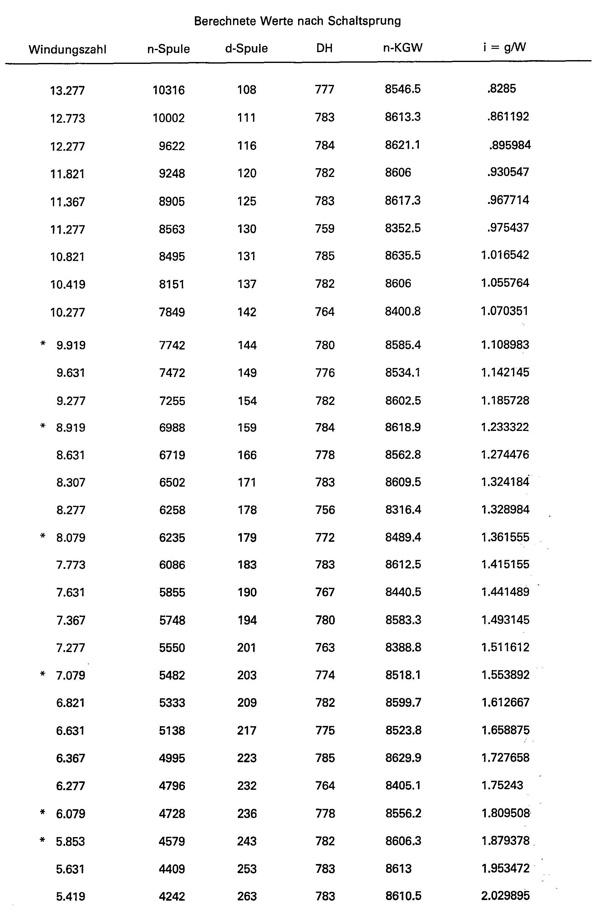

Claims (10)
Applications Claiming Priority (2)
| Application Number | Priority Date | Filing Date | Title |
|---|---|---|---|
| DE3401530 | 1984-01-18 | ||
| DE19843401530 DE3401530A1 (en) | 1984-01-18 | 1984-01-18 | PRECISION COIL, METHOD AND DEVICE FOR PRODUCING THE SAME |
Publications (4)
| Publication Number | Publication Date |
|---|---|
| EP0150771A2 EP0150771A2 (en) | 1985-08-07 |
| EP0150771A3 EP0150771A3 (en) | 1985-08-21 |
| EP0150771B1 EP0150771B1 (en) | 1987-05-06 |
| EP0150771B2 true EP0150771B2 (en) | 1990-10-10 |
Family
ID=6225220
Family Applications (1)
| Application Number | Title | Priority Date | Filing Date |
|---|---|---|---|
| EP85100439A Expired - Lifetime EP0150771B2 (en) | 1984-01-18 | 1985-01-17 | Precision wound package, process and device for its manufacture |
Country Status (4)
| Country | Link |
|---|---|
| US (1) | US4676441A (en) |
| EP (1) | EP0150771B2 (en) |
| JP (1) | JPS60218262A (en) |
| DE (2) | DE3401530A1 (en) |
Families Citing this family (17)
| Publication number | Priority date | Publication date | Assignee | Title |
|---|---|---|---|---|
| JPS62290682A (en) * | 1986-06-03 | 1987-12-17 | Teijin Seiki Co Ltd | Traverse device |
| EP0256383B1 (en) * | 1986-08-09 | 1990-01-31 | B a r m a g AG | Method to wind up threads |
| DE3627879C2 (en) * | 1986-08-16 | 1995-09-28 | Barmag Barmer Maschf | Process for winding threads |
| EP0260682B1 (en) * | 1986-09-18 | 1991-04-03 | TEIJIN SEIKI CO. Ltd. | Method of winding yarn on bobbin and machine therefor |
| DE3703869C2 (en) * | 1987-02-07 | 1996-12-12 | Schlafhorst & Co W | Method for monitoring and / or controlling the winding process and winding unit for executing the method |
| US5156347A (en) * | 1988-03-30 | 1992-10-20 | Gay Ii Francis V | Automatic continuous fiber winder |
| IT1227912B (en) * | 1988-12-23 | 1991-05-14 | Savio Spa | PROCEDURE AND APPARATUS TO DRIVE THE DISTRIBUTION OF THE WIRE ON THE PACKAGE IN FORMATION IN A COLLECTION GROUP FOR SYNTHETIC WIRES |
| DE3918846A1 (en) * | 1989-06-09 | 1990-12-13 | Maag Fritjof | PRAEZISION CROSS COIL, METHOD FOR THE PRODUCTION AND COIL INSTALLATION THEREFOR |
| IT1251866B (en) * | 1991-09-24 | 1995-05-26 | Fadis Spa | METHOD FOR CHECKING THE POSITION OF THE YARN REVERSAL POINT, PARTICULARLY FOR ROCKING MACHINES AND RELATED EQUIPMENT |
| IT1251429B (en) * | 1991-10-25 | 1995-05-09 | Savio Spa | WIRE DISTRIBUTION PROCEDURE IN A SPOOLER GROUP |
| DE4208395A1 (en) * | 1992-03-16 | 1993-09-23 | Sahm Georg Fa | METHOD FOR REWINDING, TAPE OR THREADED DISHWOOD FROM A WINDING DEVICE IN CROSS WINDING WITH PRECISION WINDING |
| DE4208393A1 (en) * | 1992-03-16 | 1993-09-23 | Sahm Georg Fa | METHOD FOR REWINDING CONTINUOUSLY WITH PREFERRED, CONSTANT SPEED OF A THREADED DEVICE, THREAD-SHAPED GOODS IN STEPPED PRECISION CROSSWINDING, AND REEL DEVICE FOR IMPLEMENTING THIS |
| CH691474A5 (en) * | 1992-11-13 | 2001-07-31 | Rieter Ag Maschf | Method and apparatus for winding a yarn. |
| AU6270698A (en) | 1997-02-05 | 1998-08-25 | Plant Engineering Consultants, Inc. | Precision winding method and apparatus |
| JP2004500295A (en) * | 1999-10-19 | 2004-01-08 | マシーネンファブリク リーター アクチェンゲゼルシャフト | Method and apparatus for winding a yarn on a bobbin |
| US6568623B1 (en) * | 2000-03-21 | 2003-05-27 | Owens-Corning Fiberglas Technology, Inc. | Method for controlling wind angle and waywind during strand package buildup |
| CN116135760B (en) * | 2023-04-14 | 2023-06-23 | 广东包庄科技有限公司 | Rolling optimization method and device, electronic equipment and storage medium |
Family Cites Families (11)
| Publication number | Priority date | Publication date | Assignee | Title |
|---|---|---|---|---|
| DE1059812B (en) * | 1949-07-28 | 1959-06-18 | Walter P Taylor | Process for winding a precision cheese or the like and machine for practicing the process as well as cheese made according to this process |
| US3638872A (en) * | 1968-03-28 | 1972-02-01 | Du Pont | Process for winding a yarn package |
| CH603469A5 (en) * | 1975-11-05 | 1978-08-15 | Rieter Ag Maschf | |
| DE3049573A1 (en) * | 1980-12-31 | 1982-07-29 | Fritjof Dipl.-Ing. Dr.-Ing. 6233 Kelkheim Maag | DEVICE FOR PRODUCING YARN BOBBINS |
| US4394986A (en) * | 1981-05-13 | 1983-07-26 | Toray Industries, Inc. | Yarn winding apparatus |
| GB2112029B (en) * | 1981-11-02 | 1986-06-25 | Murata Machinery Ltd | Yarn winding methods and apparatus |
| JPS5871053U (en) * | 1981-11-04 | 1983-05-14 | 帝人株式会社 | Winding control device |
| US4504021A (en) * | 1982-03-20 | 1985-03-12 | Barmag Barmer Maschinenfabrik Ag | Ribbon free wound yarn package and method and apparatus for producing the same |
| DE3210244A1 (en) * | 1982-03-20 | 1983-09-22 | Barmag Barmer Maschinenfabrik Ag, 5630 Remscheid | Process for eliminating a bolster during the winding of a yarn by random winding |
| US4504024A (en) * | 1982-05-11 | 1985-03-12 | Barmag Barmer Maschinenfabrik Ag | Method and apparatus for producing ribbon free wound yarn package |
| EP0118173B1 (en) * | 1983-02-03 | 1988-03-09 | Celanese Corporation | Process for crosswinding filamentary yarn |
-
1984
- 1984-01-18 DE DE19843401530 patent/DE3401530A1/en not_active Withdrawn
-
1985
- 1985-01-17 DE DE8585100439T patent/DE3560159D1/en not_active Expired
- 1985-01-17 EP EP85100439A patent/EP0150771B2/en not_active Expired - Lifetime
- 1985-01-18 JP JP60008281A patent/JPS60218262A/en active Pending
-
1986
- 1986-06-27 US US06/880,635 patent/US4676441A/en not_active Expired - Fee Related
Also Published As
| Publication number | Publication date |
|---|---|
| DE3560159D1 (en) | 1987-06-11 |
| US4676441A (en) | 1987-06-30 |
| EP0150771A3 (en) | 1985-08-21 |
| EP0150771A2 (en) | 1985-08-07 |
| EP0150771B1 (en) | 1987-05-06 |
| DE3401530A1 (en) | 1985-07-25 |
| JPS60218262A (en) | 1985-10-31 |
Similar Documents
| Publication | Publication Date | Title |
|---|---|---|
| EP0150771B2 (en) | Precision wound package, process and device for its manufacture | |
| DE69128939T3 (en) | STRUCTURE OF A THREAD WINDING | |
| DE2649780C3 (en) | Winding machine for textile yarns | |
| DE3332382C2 (en) | ||
| EP0237892B1 (en) | Process and device for copping a thread | |
| DE3809635C2 (en) | ||
| EP0561188B1 (en) | Procedure for the precision crosswinding of ribbon-like or yarn-like material | |
| EP0256411B1 (en) | Method to wind up threads | |
| AT502782B1 (en) | BANDAUFWICKELVERFAHREN | |
| DE4223271C1 (en) | ||
| EP0256383B1 (en) | Method to wind up threads | |
| EP1951605A1 (en) | Method for avoiding ribbon windings | |
| DE10015933B4 (en) | Method for producing a step precision winding | |
| EP0712374B2 (en) | Winding machine for yarn at constant speed | |
| DE3911854C2 (en) | ||
| CH693380A5 (en) | Method and device for winding a continuously advancing yarn. | |
| EP0386519B1 (en) | Method and device for winding a predetermined length of yarn in layers on a bobbin | |
| DE19817111A1 (en) | Method of winding yarn on cylindrical cross wound bobbin | |
| EP0093258B1 (en) | Method of avoiding images at the random cross winding of a yarn | |
| DE3030504C2 (en) | Method and device for producing yarn bobbins with a given yarn length on rotor spinning machines | |
| DE4112768A1 (en) | Computer control for precision winding of cheese packages - using parameters which depend only on bare tube dia. | |
| DE3210244A1 (en) | Process for eliminating a bolster during the winding of a yarn by random winding | |
| EP0710616A1 (en) | Procedure and device for winding yarns | |
| DE2752477A1 (en) | DEVICE FOR CONTROLLING THE MOVEMENTS OF THE SHEARING SLIDE CARRYING THE SHEAR BLADE OF A SHEARING MACHINE WHEN SHEARING A COIL | |
| EP0166292A1 (en) | Traversing device for a winding machine |
Legal Events
| Date | Code | Title | Description |
|---|---|---|---|
| PUAI | Public reference made under article 153(3) epc to a published international application that has entered the european phase |
Free format text: ORIGINAL CODE: 0009012 |
|
| PUAL | Search report despatched |
Free format text: ORIGINAL CODE: 0009013 |
|
| AK | Designated contracting states |
Designated state(s): CH DE FR GB IT LI |
|
| AK | Designated contracting states |
Designated state(s): CH DE FR GB IT LI |
|
| 17P | Request for examination filed |
Effective date: 19850729 |
|
| 17Q | First examination report despatched |
Effective date: 19860205 |
|
| GRAA | (expected) grant |
Free format text: ORIGINAL CODE: 0009210 |
|
| AK | Designated contracting states |
Kind code of ref document: B1 Designated state(s): CH DE FR GB IT LI |
|
| ITF | It: translation for a ep patent filed |
Owner name: ING. C. GREGORJ S.P.A. |
|
| REF | Corresponds to: |
Ref document number: 3560159 Country of ref document: DE Date of ref document: 19870611 |
|
| ET | Fr: translation filed | ||
| PLBI | Opposition filed |
Free format text: ORIGINAL CODE: 0009260 |
|
| 26 | Opposition filed |
Opponent name: BARMAG AKTIENGESELLSCHAFT Effective date: 19880204 |
|
| PUAH | Patent maintained in amended form |
Free format text: ORIGINAL CODE: 0009272 |
|
| STAA | Information on the status of an ep patent application or granted ep patent |
Free format text: STATUS: PATENT MAINTAINED AS AMENDED |
|
| 27A | Patent maintained in amended form |
Effective date: 19901010 |
|
| AK | Designated contracting states |
Kind code of ref document: B2 Designated state(s): CH DE FR GB IT LI |
|
| ITF | It: translation for a ep patent filed |
Owner name: ING. C. GREGORJ S.P.A. |
|
| ET3 | Fr: translation filed ** decision concerning opposition | ||
| PGFP | Annual fee paid to national office [announced via postgrant information from national office to epo] |
Ref country code: DE Payment date: 19921212 Year of fee payment: 9 Ref country code: FR Payment date: 19921212 Year of fee payment: 9 |
|
| PGFP | Annual fee paid to national office [announced via postgrant information from national office to epo] |
Ref country code: GB Payment date: 19921214 Year of fee payment: 9 |
|
| PGFP | Annual fee paid to national office [announced via postgrant information from national office to epo] |
Ref country code: CH Payment date: 19921215 Year of fee payment: 9 |
|
| ITTA | It: last paid annual fee | ||
| PG25 | Lapsed in a contracting state [announced via postgrant information from national office to epo] |
Ref country code: GB Effective date: 19940117 |
|
| PG25 | Lapsed in a contracting state [announced via postgrant information from national office to epo] |
Ref country code: CH Effective date: 19940131 Ref country code: LI Effective date: 19940131 |
|
| GBPC | Gb: european patent ceased through non-payment of renewal fee |
Effective date: 19940117 |
|
| PG25 | Lapsed in a contracting state [announced via postgrant information from national office to epo] |
Ref country code: FR Effective date: 19940930 |
|
| REG | Reference to a national code |
Ref country code: CH Ref legal event code: PL |
|
| PG25 | Lapsed in a contracting state [announced via postgrant information from national office to epo] |
Ref country code: DE Effective date: 19941001 |
|
| REG | Reference to a national code |
Ref country code: FR Ref legal event code: ST |