EP0149410A2 - Procédé pour le contrôle du temps de soudage - Google Patents
Procédé pour le contrôle du temps de soudage Download PDFInfo
- Publication number
- EP0149410A2 EP0149410A2 EP84440054A EP84440054A EP0149410A2 EP 0149410 A2 EP0149410 A2 EP 0149410A2 EP 84440054 A EP84440054 A EP 84440054A EP 84440054 A EP84440054 A EP 84440054A EP 0149410 A2 EP0149410 A2 EP 0149410A2
- Authority
- EP
- European Patent Office
- Prior art keywords
- property
- welding
- variations
- captured
- hole
- Prior art date
- Legal status (The legal status is an assumption and is not a legal conclusion. Google has not performed a legal analysis and makes no representation as to the accuracy of the status listed.)
- Granted
Links
Images
Classifications
-
- B—PERFORMING OPERATIONS; TRANSPORTING
- B29—WORKING OF PLASTICS; WORKING OF SUBSTANCES IN A PLASTIC STATE IN GENERAL
- B29C—SHAPING OR JOINING OF PLASTICS; SHAPING OF MATERIAL IN A PLASTIC STATE, NOT OTHERWISE PROVIDED FOR; AFTER-TREATMENT OF THE SHAPED PRODUCTS, e.g. REPAIRING
- B29C66/00—General aspects of processes or apparatus for joining preformed parts
- B29C66/50—General aspects of joining tubular articles; General aspects of joining long products, i.e. bars or profiled elements; General aspects of joining single elements to tubular articles, hollow articles or bars; General aspects of joining several hollow-preforms to form hollow or tubular articles
- B29C66/51—Joining tubular articles, profiled elements or bars; Joining single elements to tubular articles, hollow articles or bars; Joining several hollow-preforms to form hollow or tubular articles
- B29C66/52—Joining tubular articles, bars or profiled elements
- B29C66/522—Joining tubular articles
- B29C66/5221—Joining tubular articles for forming coaxial connections, i.e. the tubular articles to be joined forming a zero angle relative to each other
-
- B—PERFORMING OPERATIONS; TRANSPORTING
- B29—WORKING OF PLASTICS; WORKING OF SUBSTANCES IN A PLASTIC STATE IN GENERAL
- B29C—SHAPING OR JOINING OF PLASTICS; SHAPING OF MATERIAL IN A PLASTIC STATE, NOT OTHERWISE PROVIDED FOR; AFTER-TREATMENT OF THE SHAPED PRODUCTS, e.g. REPAIRING
- B29C65/00—Joining or sealing of preformed parts, e.g. welding of plastics materials; Apparatus therefor
- B29C65/02—Joining or sealing of preformed parts, e.g. welding of plastics materials; Apparatus therefor by heating, with or without pressure
- B29C65/34—Joining or sealing of preformed parts, e.g. welding of plastics materials; Apparatus therefor by heating, with or without pressure using heated elements which remain in the joint, e.g. "verlorenes Schweisselement"
- B29C65/3404—Joining or sealing of preformed parts, e.g. welding of plastics materials; Apparatus therefor by heating, with or without pressure using heated elements which remain in the joint, e.g. "verlorenes Schweisselement" characterised by the type of heated elements which remain in the joint
- B29C65/342—Joining or sealing of preformed parts, e.g. welding of plastics materials; Apparatus therefor by heating, with or without pressure using heated elements which remain in the joint, e.g. "verlorenes Schweisselement" characterised by the type of heated elements which remain in the joint comprising at least a single wire, e.g. in the form of a winding
-
- B—PERFORMING OPERATIONS; TRANSPORTING
- B29—WORKING OF PLASTICS; WORKING OF SUBSTANCES IN A PLASTIC STATE IN GENERAL
- B29C—SHAPING OR JOINING OF PLASTICS; SHAPING OF MATERIAL IN A PLASTIC STATE, NOT OTHERWISE PROVIDED FOR; AFTER-TREATMENT OF THE SHAPED PRODUCTS, e.g. REPAIRING
- B29C65/00—Joining or sealing of preformed parts, e.g. welding of plastics materials; Apparatus therefor
- B29C65/02—Joining or sealing of preformed parts, e.g. welding of plastics materials; Apparatus therefor by heating, with or without pressure
- B29C65/34—Joining or sealing of preformed parts, e.g. welding of plastics materials; Apparatus therefor by heating, with or without pressure using heated elements which remain in the joint, e.g. "verlorenes Schweisselement"
- B29C65/3472—Joining or sealing of preformed parts, e.g. welding of plastics materials; Apparatus therefor by heating, with or without pressure using heated elements which remain in the joint, e.g. "verlorenes Schweisselement" characterised by the composition of the heated elements which remain in the joint
- B29C65/3476—Joining or sealing of preformed parts, e.g. welding of plastics materials; Apparatus therefor by heating, with or without pressure using heated elements which remain in the joint, e.g. "verlorenes Schweisselement" characterised by the composition of the heated elements which remain in the joint being metallic
-
- B—PERFORMING OPERATIONS; TRANSPORTING
- B29—WORKING OF PLASTICS; WORKING OF SUBSTANCES IN A PLASTIC STATE IN GENERAL
- B29C—SHAPING OR JOINING OF PLASTICS; SHAPING OF MATERIAL IN A PLASTIC STATE, NOT OTHERWISE PROVIDED FOR; AFTER-TREATMENT OF THE SHAPED PRODUCTS, e.g. REPAIRING
- B29C66/00—General aspects of processes or apparatus for joining preformed parts
- B29C66/50—General aspects of joining tubular articles; General aspects of joining long products, i.e. bars or profiled elements; General aspects of joining single elements to tubular articles, hollow articles or bars; General aspects of joining several hollow-preforms to form hollow or tubular articles
- B29C66/51—Joining tubular articles, profiled elements or bars; Joining single elements to tubular articles, hollow articles or bars; Joining several hollow-preforms to form hollow or tubular articles
- B29C66/52—Joining tubular articles, bars or profiled elements
- B29C66/522—Joining tubular articles
- B29C66/5229—Joining tubular articles involving the use of a socket
-
- B—PERFORMING OPERATIONS; TRANSPORTING
- B29—WORKING OF PLASTICS; WORKING OF SUBSTANCES IN A PLASTIC STATE IN GENERAL
- B29C—SHAPING OR JOINING OF PLASTICS; SHAPING OF MATERIAL IN A PLASTIC STATE, NOT OTHERWISE PROVIDED FOR; AFTER-TREATMENT OF THE SHAPED PRODUCTS, e.g. REPAIRING
- B29C66/00—General aspects of processes or apparatus for joining preformed parts
- B29C66/90—Measuring or controlling the joining process
- B29C66/91—Measuring or controlling the joining process by measuring or controlling the temperature, the heat or the thermal flux
- B29C66/912—Measuring or controlling the joining process by measuring or controlling the temperature, the heat or the thermal flux by measuring the temperature, the heat or the thermal flux
- B29C66/9121—Measuring or controlling the joining process by measuring or controlling the temperature, the heat or the thermal flux by measuring the temperature, the heat or the thermal flux by measuring the temperature
- B29C66/91211—Measuring or controlling the joining process by measuring or controlling the temperature, the heat or the thermal flux by measuring the temperature, the heat or the thermal flux by measuring the temperature with special temperature measurement means or methods
- B29C66/91216—Measuring or controlling the joining process by measuring or controlling the temperature, the heat or the thermal flux by measuring the temperature, the heat or the thermal flux by measuring the temperature with special temperature measurement means or methods enabling contactless temperature measurements, e.g. using a pyrometer
-
- B—PERFORMING OPERATIONS; TRANSPORTING
- B29—WORKING OF PLASTICS; WORKING OF SUBSTANCES IN A PLASTIC STATE IN GENERAL
- B29C—SHAPING OR JOINING OF PLASTICS; SHAPING OF MATERIAL IN A PLASTIC STATE, NOT OTHERWISE PROVIDED FOR; AFTER-TREATMENT OF THE SHAPED PRODUCTS, e.g. REPAIRING
- B29C66/00—General aspects of processes or apparatus for joining preformed parts
- B29C66/90—Measuring or controlling the joining process
- B29C66/91—Measuring or controlling the joining process by measuring or controlling the temperature, the heat or the thermal flux
- B29C66/912—Measuring or controlling the joining process by measuring or controlling the temperature, the heat or the thermal flux by measuring the temperature, the heat or the thermal flux
- B29C66/9121—Measuring or controlling the joining process by measuring or controlling the temperature, the heat or the thermal flux by measuring the temperature, the heat or the thermal flux by measuring the temperature
- B29C66/91221—Measuring or controlling the joining process by measuring or controlling the temperature, the heat or the thermal flux by measuring the temperature, the heat or the thermal flux by measuring the temperature of the parts to be joined
-
- B—PERFORMING OPERATIONS; TRANSPORTING
- B29—WORKING OF PLASTICS; WORKING OF SUBSTANCES IN A PLASTIC STATE IN GENERAL
- B29C—SHAPING OR JOINING OF PLASTICS; SHAPING OF MATERIAL IN A PLASTIC STATE, NOT OTHERWISE PROVIDED FOR; AFTER-TREATMENT OF THE SHAPED PRODUCTS, e.g. REPAIRING
- B29C66/00—General aspects of processes or apparatus for joining preformed parts
- B29C66/90—Measuring or controlling the joining process
- B29C66/91—Measuring or controlling the joining process by measuring or controlling the temperature, the heat or the thermal flux
- B29C66/914—Measuring or controlling the joining process by measuring or controlling the temperature, the heat or the thermal flux by controlling or regulating the temperature, the heat or the thermal flux
- B29C66/9141—Measuring or controlling the joining process by measuring or controlling the temperature, the heat or the thermal flux by controlling or regulating the temperature, the heat or the thermal flux by controlling or regulating the temperature
- B29C66/91411—Measuring or controlling the joining process by measuring or controlling the temperature, the heat or the thermal flux by controlling or regulating the temperature, the heat or the thermal flux by controlling or regulating the temperature of the parts to be joined, e.g. the joining process taking the temperature of the parts to be joined into account
-
- B—PERFORMING OPERATIONS; TRANSPORTING
- B29—WORKING OF PLASTICS; WORKING OF SUBSTANCES IN A PLASTIC STATE IN GENERAL
- B29C—SHAPING OR JOINING OF PLASTICS; SHAPING OF MATERIAL IN A PLASTIC STATE, NOT OTHERWISE PROVIDED FOR; AFTER-TREATMENT OF THE SHAPED PRODUCTS, e.g. REPAIRING
- B29C66/00—General aspects of processes or apparatus for joining preformed parts
- B29C66/90—Measuring or controlling the joining process
- B29C66/91—Measuring or controlling the joining process by measuring or controlling the temperature, the heat or the thermal flux
- B29C66/914—Measuring or controlling the joining process by measuring or controlling the temperature, the heat or the thermal flux by controlling or regulating the temperature, the heat or the thermal flux
- B29C66/9161—Measuring or controlling the joining process by measuring or controlling the temperature, the heat or the thermal flux by controlling or regulating the temperature, the heat or the thermal flux by controlling or regulating the heat or the thermal flux, i.e. the heat flux
- B29C66/91651—Measuring or controlling the joining process by measuring or controlling the temperature, the heat or the thermal flux by controlling or regulating the temperature, the heat or the thermal flux by controlling or regulating the heat or the thermal flux, i.e. the heat flux by controlling or regulating the heat generated by Joule heating or induction heating
- B29C66/91655—Measuring or controlling the joining process by measuring or controlling the temperature, the heat or the thermal flux by controlling or regulating the temperature, the heat or the thermal flux by controlling or regulating the heat or the thermal flux, i.e. the heat flux by controlling or regulating the heat generated by Joule heating or induction heating by controlling or regulating the current intensity
-
- G—PHYSICS
- G05—CONTROLLING; REGULATING
- G05D—SYSTEMS FOR CONTROLLING OR REGULATING NON-ELECTRIC VARIABLES
- G05D23/00—Control of temperature
- G05D23/19—Control of temperature characterised by the use of electric means
- G05D23/275—Control of temperature characterised by the use of electric means with sensing element expanding, contracting, or fusing in response to changes of temperature
- G05D23/27535—Details of the sensing element
- G05D23/27543—Details of the sensing element using the controlled element as sensing element
-
- B—PERFORMING OPERATIONS; TRANSPORTING
- B29—WORKING OF PLASTICS; WORKING OF SUBSTANCES IN A PLASTIC STATE IN GENERAL
- B29C—SHAPING OR JOINING OF PLASTICS; SHAPING OF MATERIAL IN A PLASTIC STATE, NOT OTHERWISE PROVIDED FOR; AFTER-TREATMENT OF THE SHAPED PRODUCTS, e.g. REPAIRING
- B29C66/00—General aspects of processes or apparatus for joining preformed parts
- B29C66/70—General aspects of processes or apparatus for joining preformed parts characterised by the composition, physical properties or the structure of the material of the parts to be joined; Joining with non-plastics material
- B29C66/73—General aspects of processes or apparatus for joining preformed parts characterised by the composition, physical properties or the structure of the material of the parts to be joined; Joining with non-plastics material characterised by the intensive physical properties of the material of the parts to be joined, by the optical properties of the material of the parts to be joined, by the extensive physical properties of the parts to be joined, by the state of the material of the parts to be joined or by the material of the parts to be joined being a thermoplastic or a thermoset
- B29C66/739—General aspects of processes or apparatus for joining preformed parts characterised by the composition, physical properties or the structure of the material of the parts to be joined; Joining with non-plastics material characterised by the intensive physical properties of the material of the parts to be joined, by the optical properties of the material of the parts to be joined, by the extensive physical properties of the parts to be joined, by the state of the material of the parts to be joined or by the material of the parts to be joined being a thermoplastic or a thermoset characterised by the material of the parts to be joined being a thermoplastic or a thermoset
- B29C66/7392—General aspects of processes or apparatus for joining preformed parts characterised by the composition, physical properties or the structure of the material of the parts to be joined; Joining with non-plastics material characterised by the intensive physical properties of the material of the parts to be joined, by the optical properties of the material of the parts to be joined, by the extensive physical properties of the parts to be joined, by the state of the material of the parts to be joined or by the material of the parts to be joined being a thermoplastic or a thermoset characterised by the material of the parts to be joined being a thermoplastic or a thermoset characterised by the material of at least one of the parts being a thermoplastic
- B29C66/73921—General aspects of processes or apparatus for joining preformed parts characterised by the composition, physical properties or the structure of the material of the parts to be joined; Joining with non-plastics material characterised by the intensive physical properties of the material of the parts to be joined, by the optical properties of the material of the parts to be joined, by the extensive physical properties of the parts to be joined, by the state of the material of the parts to be joined or by the material of the parts to be joined being a thermoplastic or a thermoset characterised by the material of the parts to be joined being a thermoplastic or a thermoset characterised by the material of at least one of the parts being a thermoplastic characterised by the materials of both parts being thermoplastics
-
- B—PERFORMING OPERATIONS; TRANSPORTING
- B29—WORKING OF PLASTICS; WORKING OF SUBSTANCES IN A PLASTIC STATE IN GENERAL
- B29C—SHAPING OR JOINING OF PLASTICS; SHAPING OF MATERIAL IN A PLASTIC STATE, NOT OTHERWISE PROVIDED FOR; AFTER-TREATMENT OF THE SHAPED PRODUCTS, e.g. REPAIRING
- B29C66/00—General aspects of processes or apparatus for joining preformed parts
- B29C66/90—Measuring or controlling the joining process
- B29C66/94—Measuring or controlling the joining process by measuring or controlling the time
-
- B—PERFORMING OPERATIONS; TRANSPORTING
- B29—WORKING OF PLASTICS; WORKING OF SUBSTANCES IN A PLASTIC STATE IN GENERAL
- B29C—SHAPING OR JOINING OF PLASTICS; SHAPING OF MATERIAL IN A PLASTIC STATE, NOT OTHERWISE PROVIDED FOR; AFTER-TREATMENT OF THE SHAPED PRODUCTS, e.g. REPAIRING
- B29C66/00—General aspects of processes or apparatus for joining preformed parts
- B29C66/90—Measuring or controlling the joining process
- B29C66/96—Measuring or controlling the joining process characterised by the method for implementing the controlling of the joining process
- B29C66/961—Measuring or controlling the joining process characterised by the method for implementing the controlling of the joining process involving a feedback loop mechanism, e.g. comparison with a desired value
Definitions
- zones S are the welding zones and the zones f are the cold zones, which prevent the molten material to escape laterally, which would harm the establishment of the pressure,
Abstract
Description
- La présente invention concerne la mise en oeuvre des raccords électrosoudables pour tubes en matière plastique. Elle vise plus spécialement un procédé et un dispositif assurant dans cette mise en oeuvre la durée de soudure optimale en fonction du diamètre des tubes.
- Par "raccord" on désigne ici, aussi bien un manchon servant à relier les extrémités de deux tubes dans le prolongement l'un de l'autre, qu'une prise pratiquée transversalement sur un autre tube, ou que tout autre dispositif dans lequel un certain nombre d'éléments tubulaires doivent être associés entre eux.
- Pour la clarté de l'exposé on se référera dans la suite au cas particulier d'un manchon tel que défini ci-dessus, étant entendu qu'il ne s'agit que d'un exemple d'illustration de la technique de l'invention.
- Il est connu, pour réunir deux tubes en matière plastique, d'utiliser un manchon de même matière, dans lequel sont enfilés les deux tubes, c'est-à-dire jouant le rôle de raccord, et dans la zone superficielle interne duquel est noyé un enroulement dont les extrémités sont réunies à une source de courant électrique. Quand cette source est excitée, le passage du courant dans l'enroulement détermine la fusion de la matière dans la zone superficielle interne du manchon et dans la zone superficielle externe des tubes qui y sont enfilés. Ces deux zones subissent au surplus une certaine dilatation thermique, de sorte que les surfaces en fusion viennent en contact intime, ce qui assure leur soudure au refroidissement, avec formation d'un bloc unitaire.
- Ce processus simple comporte cependant une difficulté de contrôlé, car il n'est pas visible de l'extérieur, mais au contraire, constitue un phénomène progressif, dont l'aboutissement est la formation d'un bloc unitaire entre les tubes et leur manchon de raccordement, mais que ce phénomène peut être suivi par deux indices physiques, la température et le volume.
- En effet, quand la source de courant électrique de soudure est excitée, le passage du courant dans l'enroulement détermine une succession de faits :
- - les spires de l'enroulement étant noyées dans la matière au manchon la chaleur développée par le passage du courant provoque l'échauffement de cette matière dans leur voisinage immédiat, puis de proche en proche sa fusion et sa dilatation jusqu'à sa surface, qui va venir au contact de la surface extérieure du tube, sur laquelle elle exercera une pression croissante :
- - à son tour la matière du tube entre en fusion, ce qui assure la soudure sous pression du tube avec le manchon ;
- - si le courant n'est pas coupé en ce point, la dilatation de la matière en fusion provoquera un accroissement de pression dans la zone de soudure, car les zones latérales de chaque côté de l'enroulement demeurent froides pour éviter l'échappement de matière et assurer l'établissement de la pression de soudure.
- C'est donc grâce au contrôle de la température ou du volume de la matière que l'on peut déclencher l'arrêt du passage du courant au moment où, l'un de ces deux indices ayant atteint une valeur déterminée, il est certain que la soudure est achevée, la durée optimale de passage du courant étant fonction du diamètre du manchon la tension étant supposée constante.
- Il existait donc un besoin de moyens permettant d'assurer un contrôle automatique du temps de soudage de ces raccords et la présente invention vise de tels moyens.
- Selon l'invention, le passage du courant est automatiquement interrompu dès que les propriétés de la matière du raccord des tubes correspondent à la soudure optimale. A cet effet, selon un premier mode de mise en oeuvre de l'invention, c'est la matière en fusion elle-même qui, en se dilatant thermiquement, arrive au contact d'un composant électromécanique ou électronique qui intervient alors pour interrompre le passage du courant.
- Selon un second mode de mise en oeuvre de l'invention, c'est la température de la matière qui est prise comme variable, et qui, quand elle a atteint la valeur correspondant au degré de ramollissement ou de fusion voulue détermine soit, l'envoi, par une thermosonde, d'une information d'arrêt à la source de courant, soit la coupure de courant par rupture, par fusion, d'une zone sensible à la chaleur de l'enroulement.
- Selon un troisième mode de mise en oeuvre, c'est un élément sensible à la dureté ou à la consistance de la matière qui, en s'enfonçant dans cette matière ramollie, détermine le fonctionnement d'un composant électro-mécanique ou électronique.
- D'autres modes de mise en oeuvre peuvent encore être imaginés, en restant dans le cadre de l'invention, dès lors qu'une propriété liée au ramollissement de la matière aura été captée et utilisée comme information transmise à un système d'arrêt du courant de soudure.
- L'invention vise donc en premier lieu un procédé pour le contrôle du temps de soudage d'un manchon êlectrosoudable, ce procédé consistant à utiliser les variations de propriétés de la matière plastique en fusion pour agir, au moment où une de ces propriétés atteint son degré optimal, sur un composant électromécanique ou électronique qui arrête le passage du courant électrique.
- Dans la mise en pratique du premier mode de réalisation de l'invention, on utilisera l'écoulement de la matière en fusion par un trou radial pratiqué dans la paroi du manchon. Au moment de l'opération de soudage, la matière en fusion provenant de la zone interne du manchon est refoulée par ce trou, et affleure la surface externe du manchon. Ce phénomène bien connu a été exploité pour tenter d'exercer un contrôle visuel de l'opération, en plaçant un "flotteur" dans le trou, mais un tel moyen est trcp rustique pour constituer un véritable contrôle rigoureux. Selon l'invention, un micro-interrupteur est placé à l'orifice du trou, de matière telle qu'il est actionné par la matière en fusion à l'instant même où elle parvient à son contact, ce qui réalise un contrôle réellement rigoureux.
- L'invention vise donc également un dispositif pour le contrôle du temps de soudage d'un manchon électrosoudable, du type dans lequel un trou est percé radialement dans la paroi du manchon jusqu'au voisinage de l'enroulement, la matière en fusion s'écoulant par ce trou jusqu'au voisinage de la face externe du manchon, ce dispositif consistant en un élément électro-mécanique ou électronique placé au voisinage de l'embouchure du trou et intervenant pour couper le courant dès qu'il est atteint par ladite matière en fusion.
- Bien entendu, le diamètre du trou doit être choisi en fonction de la dimension du manchon de manière que la quantité de matière en fusion qui y remonte soit telle qu'elle atteigne l'élément de contrôle au moment précis où le soudage est cptima1 et où il faut interrompre le passage du courant.
- Les dessins annexés illustrent la mise en oeuvre de ce premier mode de réalisation du procédé dans deux applications distinctes. Sur ce dessin
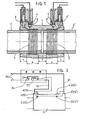
- - la figure 1 illustre l'application de l'invention au raccord de deux tubes coaxiaux par un manchon,
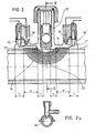
- - la figure 2 illustre l'application de l'invention à la pose d'un tube de dérivation sur une conduite principale,
- - la figure 2a est une coupe suivant II-II de la figure 2,
- - et la figure 3 illustre schématiquement la commande du circuit de soudage par la mise en oeuvre de ce procédé.
- Si l'on se réfère d'abord à la figure 1, on.y a représenté un manchon 1 en matière thermoplastique, par exemple du polyéthylène haute densité, destiné à raccorder deux tube: coaxiaux 2-2', par exemple en polyéthylène, d'un diamètre externe très légèrement inférieur au diamètre interne du manchen 1, les deux tubes 2-2' sont introduits dans le manchon 1 de manière généralement symétrique, de sorte que leurs extrémités sont situées face à des zones du manchon dans lesquelles sont noyés des enroulements 3-3' reliés ensemble par des bornes 6-6' à une source d'énergie électrique, comme il est illustré à la figure 3.
- Selon l'invention, le circuit d'alimentation du couple d'enroulement 3-3', une fois fermé par l'opérateur, comme il sera exposé à propos de la figure 3, est automatiquement coupé dès que le soudage est effectué, grâce à un circuit de contrôle commandé par deux micro-interrupteurs désignés par 4-4' disposés dans des puits 5-5' voisins des bornes 6-6', et creusés dans la paroi du manchon 1 jusqu'au voisinage des enroulements 3-3'.
- Quand le processus de fusion-dilatation rappelé plus haut se déroule, la matière en fusion du manchon, sous l'effet de la pression de dilatation, pénètre dans le fond de chaque puits 5-5', et par poursuite de cette dilatation, monte dans ce puits jusqu'à venir exercer sur chaque micro-interrupteur 4-4' une pression qui, repoussant le plongeur de ce micro-interrupteur, provoque sa manoeuvre de coupure du courant d'ex- citatioh des enroulements, en interrompant l'opération de soudure qui est ainsi achevée.
- Le processus est le même dans le cas de l'application des figures 2-2a, dans lesquelles, au lieu d'un manchon de raccord de deux tubes coaxiaux, la soudure est pratiquée sur une selle 10 recouvrant tout ou partie d'un tube II et servant à pratiquer dans ce tube une dérivation. A cet effet, la selle 10 porte un tube 12 fileté intérieurement pour permettre, grâce à un poinçon fileté (non représenté), de percer un orifice 13 dans la paroi du tube 11 face au tube 12.
- La selle 10 comporte un enroulement 14, galbé pour s'adapter à la forme cintrée de la selle,et excité par un circuit monté sur les bornes principales 15-15', tandis que des micrc-interrupteurs 16-16' sont logés dans des puits 17-17' de façon semblables aux micro-interrupteurs 4-4' logés dans les puits 5-5' de la figure 1.La mise en oeuvre du procédé est semblable : dès que la matière de la selle et du tube a atteint le degré de fusion voulu, elle pénètre dans les puits 16-16' et déclenche les micrc-interrupteurs 16-16' en coupant le circuit d'alimentation de l'enroulement 14,ce qui met fin au processur de soudage.
- Bien entendu, deux applications seulement du procédé ont été décrites, mais il est évident que d'autres variantes seront aisées à concevoir, notamment faisant intervenir la température proprement dite de la matière en fusion.
- La figure 3 illustre très schématiquement le montage électrique tel qu'il vient d'être décrit. Depuis un générateur basse tension 20, des conducteurs 21-22 vont alimenter les bornes principales 6-6' (15-15') de l'enroulement de soudure. Sur le conducteur 22 est interposé un système de contrôle comportant un relais 23, dont l'enclenchement se fait manuellement par un bouton-poussois 24, et le déclenchement se fait par les micro-interrupteurs 4-4' (16-16') dont les palpeurs sont sensibles à la pression de la matière en fusion dans les puits 5-5' (17-17') pratiqués dans le manchon 1 (ou la selle 10).
- Selon des variantes rentrant dans le cadre de l'invention, ces palpeurs peuvent également être sensibles à la température, et le système de contrôle du circuit peut être commandé, soit uniquement à partir de la température, soit uniquement à partir du volume de matière, soit, puisqu'il y a deux puits dans chaque manchon à partir de la température d'un côté et du volume de l'autre.
- On notera sur les figures 1 et 2 l'indication de zones désignées par "f" et "S" sur le manchon 1 et la selle 10. Les zones S sont les zones de soudure et les zones f sont les zones froides, qui empêchent la matière en fusion de s'échapper latéralement, ce qui nuirait à l'établissement de la pression,
Claims (10)
Priority Applications (1)
| Application Number | Priority Date | Filing Date | Title |
|---|---|---|---|
| AT84440054T ATE49729T1 (de) | 1983-12-19 | 1984-11-19 | Verfahren zum ueberwachen der schweisszeit. |
Applications Claiming Priority (2)
| Application Number | Priority Date | Filing Date | Title |
|---|---|---|---|
| FR8320429A FR2555936B1 (fr) | 1983-12-19 | 1983-12-19 | Procede pour le controle du temps de soudage |
| FR8320429 | 1983-12-19 |
Publications (3)
| Publication Number | Publication Date |
|---|---|
| EP0149410A2 true EP0149410A2 (fr) | 1985-07-24 |
| EP0149410A3 EP0149410A3 (en) | 1985-12-18 |
| EP0149410B1 EP0149410B1 (fr) | 1990-01-24 |
Family
ID=9295374
Family Applications (1)
| Application Number | Title | Priority Date | Filing Date |
|---|---|---|---|
| EP84440054A Expired - Lifetime EP0149410B1 (fr) | 1983-12-19 | 1984-11-19 | Procédé pour le contrôle du temps de soudage |
Country Status (4)
| Country | Link |
|---|---|
| EP (1) | EP0149410B1 (fr) |
| AT (1) | ATE49729T1 (fr) |
| DE (1) | DE3481113D1 (fr) |
| FR (1) | FR2555936B1 (fr) |
Cited By (11)
| Publication number | Priority date | Publication date | Assignee | Title |
|---|---|---|---|---|
| EP0229743A1 (fr) * | 1986-01-08 | 1987-07-22 | Geberit AG | Dispositif comportant un manchon électro-soudable et une tête de branchement |
| FR2600008A2 (fr) * | 1983-12-19 | 1987-12-18 | Innoge Sam | Dispositif pour le controle du temps de soudage |
| EP0297185A1 (fr) * | 1985-11-08 | 1989-01-04 | R.W. LYALL & COMPANY, INC. | Procédé et appareil pour la réalisation de connexions soudées |
| US4852914A (en) * | 1987-06-19 | 1989-08-01 | Milfuse Systems, Inc. | Plastic pipeline having rapidly fusible joints and method of making same |
| EP0352128A2 (fr) * | 1988-07-21 | 1990-01-24 | Mitsui Petrochemical Industries, Ltd. | Manchon électrosoudable pourvu de moyens d'indication de l'état de la soudure |
| EP0376773A2 (fr) * | 1988-12-29 | 1990-07-04 | Gaz De France (Service National) | Dispositif pour détecter, au cours du soudage, des variations dans l'état physique de la matière plastique d'une pièce de raccordement prévue pour la jonction de tubes |
| US4943706A (en) * | 1988-04-18 | 1990-07-24 | R. W. Lyall & Company, Inc. | Method and apparatus for fusing thermoplastic materials |
| FR2695173A1 (fr) * | 1992-09-01 | 1994-03-04 | Gaz De France | Pièce d'assemblage de type rivet, ensemble constitué par un tel rivet fixé sur une pièce électriquement conductrice, pièces de raccordement équipées d'un tel ensemble et leur procédé de fabrication. |
| US5369248A (en) * | 1992-09-01 | 1994-11-29 | Gaz De France | Electro-weldable connecting piece having connection terminals and its method of manufacture |
| CN101053999B (zh) * | 2007-05-29 | 2010-06-16 | 广东联塑科技实业有限公司 | 使钢带增强聚乙烯螺旋波纹管便于相互连接的加工方法 |
| CN109140103A (zh) * | 2018-09-05 | 2019-01-04 | 浙江伟星新型建材股份有限公司 | 一种熔断式电熔管件 |
Families Citing this family (1)
| Publication number | Priority date | Publication date | Assignee | Title |
|---|---|---|---|---|
| FR2609933B1 (fr) * | 1986-12-23 | 1989-06-09 | Gaz De France | Procede pour conduire et controler l'elevation de temperature de pieces chauffees electriquement |
Citations (11)
| Publication number | Priority date | Publication date | Assignee | Title |
|---|---|---|---|---|
| US2524886A (en) * | 1945-11-21 | 1950-10-10 | Collins Radio Co | Temperature control of electrovibratory systems |
| US2870297A (en) * | 1957-06-24 | 1959-01-20 | Hagan Chemicals & Controls Inc | Trip thermostats having sharp reference temperatures |
| FR1260490A (fr) * | 1960-06-23 | 1961-05-05 | Brown Boveri & Compagnie Sa | Dispositif pour l'assemblage de pièces ou d'éléments de pièces non métalliques,de préférence en matières thermoplastiques |
| GB873122A (en) * | 1956-02-10 | 1961-07-19 | Marconi Wireless Telegraph Co | Improvements in or relating to electrically heated thermostatically controllable containers |
| US3026392A (en) * | 1960-02-01 | 1962-03-20 | L & M Space Res And Electronic | Shunting device |
| US3046536A (en) * | 1960-05-23 | 1962-07-24 | Alfred F Sciuto | Automatic fire alarm energizing means |
| CH437755A (de) * | 1965-11-29 | 1967-06-15 | Von Roll Ag | Elektronisch gesteuertes Schweissgerät zum Verbinden von Rohren und Formstücken aus schweissbarem Kunststoff mittels eines einen elektrischen Heizwiderstand aufweisenden Verbindungsstückes |
| US3423714A (en) * | 1965-10-29 | 1969-01-21 | Int Standard Electric Corp | Wear compensated rubber thermostat |
| FR2287101A1 (fr) * | 1974-10-04 | 1976-04-30 | Micro Devices Corp | Rupteur thermique |
| FR2345652A1 (fr) * | 1976-03-22 | 1977-10-21 | Sturm Werner | Manchon soudable electriquement en matiere thermoplastique |
| EP0093821A1 (fr) * | 1982-05-12 | 1983-11-16 | Geberit AG | Manchon à souder |
-
1983
- 1983-12-19 FR FR8320429A patent/FR2555936B1/fr not_active Expired
-
1984
- 1984-11-19 DE DE8484440054T patent/DE3481113D1/de not_active Expired - Lifetime
- 1984-11-19 EP EP84440054A patent/EP0149410B1/fr not_active Expired - Lifetime
- 1984-11-19 AT AT84440054T patent/ATE49729T1/de not_active IP Right Cessation
Patent Citations (11)
| Publication number | Priority date | Publication date | Assignee | Title |
|---|---|---|---|---|
| US2524886A (en) * | 1945-11-21 | 1950-10-10 | Collins Radio Co | Temperature control of electrovibratory systems |
| GB873122A (en) * | 1956-02-10 | 1961-07-19 | Marconi Wireless Telegraph Co | Improvements in or relating to electrically heated thermostatically controllable containers |
| US2870297A (en) * | 1957-06-24 | 1959-01-20 | Hagan Chemicals & Controls Inc | Trip thermostats having sharp reference temperatures |
| US3026392A (en) * | 1960-02-01 | 1962-03-20 | L & M Space Res And Electronic | Shunting device |
| US3046536A (en) * | 1960-05-23 | 1962-07-24 | Alfred F Sciuto | Automatic fire alarm energizing means |
| FR1260490A (fr) * | 1960-06-23 | 1961-05-05 | Brown Boveri & Compagnie Sa | Dispositif pour l'assemblage de pièces ou d'éléments de pièces non métalliques,de préférence en matières thermoplastiques |
| US3423714A (en) * | 1965-10-29 | 1969-01-21 | Int Standard Electric Corp | Wear compensated rubber thermostat |
| CH437755A (de) * | 1965-11-29 | 1967-06-15 | Von Roll Ag | Elektronisch gesteuertes Schweissgerät zum Verbinden von Rohren und Formstücken aus schweissbarem Kunststoff mittels eines einen elektrischen Heizwiderstand aufweisenden Verbindungsstückes |
| FR2287101A1 (fr) * | 1974-10-04 | 1976-04-30 | Micro Devices Corp | Rupteur thermique |
| FR2345652A1 (fr) * | 1976-03-22 | 1977-10-21 | Sturm Werner | Manchon soudable electriquement en matiere thermoplastique |
| EP0093821A1 (fr) * | 1982-05-12 | 1983-11-16 | Geberit AG | Manchon à souder |
Cited By (16)
| Publication number | Priority date | Publication date | Assignee | Title |
|---|---|---|---|---|
| FR2600008A2 (fr) * | 1983-12-19 | 1987-12-18 | Innoge Sam | Dispositif pour le controle du temps de soudage |
| EP0297185A1 (fr) * | 1985-11-08 | 1989-01-04 | R.W. LYALL & COMPANY, INC. | Procédé et appareil pour la réalisation de connexions soudées |
| EP0229743A1 (fr) * | 1986-01-08 | 1987-07-22 | Geberit AG | Dispositif comportant un manchon électro-soudable et une tête de branchement |
| US4852914A (en) * | 1987-06-19 | 1989-08-01 | Milfuse Systems, Inc. | Plastic pipeline having rapidly fusible joints and method of making same |
| US4943706A (en) * | 1988-04-18 | 1990-07-24 | R. W. Lyall & Company, Inc. | Method and apparatus for fusing thermoplastic materials |
| EP0352128A3 (fr) * | 1988-07-21 | 1991-06-12 | Mitsui Petrochemical Industries, Ltd. | Manchon électrosoudable pourvu de moyens d'indication de l'état de la soudure |
| EP0352128A2 (fr) * | 1988-07-21 | 1990-01-24 | Mitsui Petrochemical Industries, Ltd. | Manchon électrosoudable pourvu de moyens d'indication de l'état de la soudure |
| EP0376773A2 (fr) * | 1988-12-29 | 1990-07-04 | Gaz De France (Service National) | Dispositif pour détecter, au cours du soudage, des variations dans l'état physique de la matière plastique d'une pièce de raccordement prévue pour la jonction de tubes |
| FR2643014A1 (fr) * | 1988-12-29 | 1990-08-17 | Gaz De France | Dispositif pour detecter, au cours du soudage, des variations dans l'etat physique de la matiere plastique d'une piece de raccordement prevue pour la jonction de tubes |
| EP0376773A3 (fr) * | 1988-12-29 | 1991-09-18 | Gaz De France (Service National) | Dispositif pour détecter, au cours du soudage, des variations dans l'état physique de la matière plastique d'une pièce de raccordement prévue pour la jonction de tubes |
| US5086213A (en) * | 1988-12-29 | 1992-02-04 | Gaz De France | Device for detecting, during welding, variation in the physical state of the plastic material in a coupling piece of joining pipes |
| FR2695173A1 (fr) * | 1992-09-01 | 1994-03-04 | Gaz De France | Pièce d'assemblage de type rivet, ensemble constitué par un tel rivet fixé sur une pièce électriquement conductrice, pièces de raccordement équipées d'un tel ensemble et leur procédé de fabrication. |
| EP0586283A1 (fr) * | 1992-09-01 | 1994-03-09 | Gaz De France | Pièce de raccordement électrosoudable à bornes de connexion perfectionnées et son procédé de fabrication |
| US5369248A (en) * | 1992-09-01 | 1994-11-29 | Gaz De France | Electro-weldable connecting piece having connection terminals and its method of manufacture |
| CN101053999B (zh) * | 2007-05-29 | 2010-06-16 | 广东联塑科技实业有限公司 | 使钢带增强聚乙烯螺旋波纹管便于相互连接的加工方法 |
| CN109140103A (zh) * | 2018-09-05 | 2019-01-04 | 浙江伟星新型建材股份有限公司 | 一种熔断式电熔管件 |
Also Published As
| Publication number | Publication date |
|---|---|
| EP0149410A3 (en) | 1985-12-18 |
| EP0149410B1 (fr) | 1990-01-24 |
| ATE49729T1 (de) | 1990-02-15 |
| FR2555936A1 (fr) | 1985-06-07 |
| FR2555936B1 (fr) | 1986-11-21 |
| DE3481113D1 (de) | 1990-03-01 |
Similar Documents
| Publication | Publication Date | Title |
|---|---|---|
| EP0149410B1 (fr) | Procédé pour le contrôle du temps de soudage | |
| EP0241597B1 (fr) | Connecteur contenant un matériau fusible et possédant une commande de température interne | |
| EP0430761B1 (fr) | Procédé et pièce de raccordement utilisant une résistance électrique pour le soudage d'éléments en matière plastique | |
| EP0430762B1 (fr) | Procédé et dispositif pour détecter une condition de chauffage d'une pièce en matière plastique et pièce de raccordement pour le soudage d'éléments également en matière plastique | |
| US4914267A (en) | Connector containing fusible material and having intrinsic temperature control | |
| JPS6324820B2 (fr) | ||
| US5107095A (en) | Clam shell heater employing high permeability material | |
| FR2497916A1 (fr) | Manchon soudable en matiere thermoplastique | |
| US5053595A (en) | Heat shrink sleeve with high mu material | |
| US5189271A (en) | Temperature self-regulating induction apparatus | |
| EP0615091A1 (fr) | Raccord thermosoudable pour tube sur un matériau plastique ainsi qu'un procédé pour le fabriquer | |
| CA2004035C (fr) | Dispositif pour detecter, au cours du soudage, des variations dans l'etat physique de la matiere plastique d'une piece de raccordement prevue pour la jonction de tubes | |
| CA1255760A (fr) | Procede pour le controle du temps de soudage | |
| EP0183615A2 (fr) | Procédé et dispositif de détection de changement de phase | |
| FR2572327A2 (fr) | Dispositif pour le controle du temps de soudage. | |
| EP0241348A1 (fr) | Procédé et dispositif de défigeage des carburants | |
| EP1167118A1 (fr) | Allume-cigares à sécurité thermique | |
| BE1004518A5 (fr) | Detecteur pour fluides a haute temperature. | |
| EP0586283B1 (fr) | Pièce de raccordement électrosoudable à bornes de connexion perfectionnées et son procédé de fabrication | |
| BE852653A (fr) | Manchon soudable electriquement en matiere thermoplastique | |
| FR2595333A1 (fr) | Dispositif permettant de rechauffer le gas-oil ou le fuel, carburants utilises par les moteurs diesel, dans le reservoir, a l'interieur du tuyau d'aspiration | |
| JP2007008125A (ja) | 管の接続方法および接続構造並びに管接続装置 | |
| JPH066345B2 (ja) | プラスチック製管継手およびその電気融着式接続方法 | |
| FR2941512A1 (fr) | Dispositif de raccordement de conduits plastiques. | |
| JPH04203585A (ja) | 電気融着継手 |
Legal Events
| Date | Code | Title | Description |
|---|---|---|---|
| PUAI | Public reference made under article 153(3) epc to a published international application that has entered the european phase |
Free format text: ORIGINAL CODE: 0009012 |
|
| AK | Designated contracting states |
Designated state(s): AT BE CH DE GB IT LI LU NL SE |
|
| PUAL | Search report despatched |
Free format text: ORIGINAL CODE: 0009013 |
|
| AK | Designated contracting states |
Designated state(s): AT BE CH DE GB IT LI LU NL SE |
|
| 17P | Request for examination filed |
Effective date: 19860606 |
|
| RAP1 | Party data changed (applicant data changed or rights of an application transferred) |
Owner name: INNOVATION GENERALE EN ABREGE INNOGE |
|
| 17Q | First examination report despatched |
Effective date: 19880317 |
|
| GRAA | (expected) grant |
Free format text: ORIGINAL CODE: 0009210 |
|
| AK | Designated contracting states |
Kind code of ref document: B1 Designated state(s): AT BE CH DE GB IT LI LU NL SE |
|
| REF | Corresponds to: |
Ref document number: 49729 Country of ref document: AT Date of ref document: 19900215 Kind code of ref document: T |
|
| ITF | It: translation for a ep patent filed |
Owner name: ST. ASSOC. MARIETTI & PIPPARELLI |
|
| REF | Corresponds to: |
Ref document number: 3481113 Country of ref document: DE Date of ref document: 19900301 |
|
| GBT | Gb: translation of ep patent filed (gb section 77(6)(a)/1977) | ||
| PLBE | No opposition filed within time limit |
Free format text: ORIGINAL CODE: 0009261 |
|
| STAA | Information on the status of an ep patent application or granted ep patent |
Free format text: STATUS: NO OPPOSITION FILED WITHIN TIME LIMIT |
|
| 26N | No opposition filed | ||
| ITTA | It: last paid annual fee | ||
| PGFP | Annual fee paid to national office [announced via postgrant information from national office to epo] |
Ref country code: LU Payment date: 19931116 Year of fee payment: 10 |
|
| PGFP | Annual fee paid to national office [announced via postgrant information from national office to epo] |
Ref country code: BE Payment date: 19931122 Year of fee payment: 10 |
|
| EPTA | Lu: last paid annual fee | ||
| PGFP | Annual fee paid to national office [announced via postgrant information from national office to epo] |
Ref country code: SE Payment date: 19940531 Year of fee payment: 10 |
|
| PG25 | Lapsed in a contracting state [announced via postgrant information from national office to epo] |
Ref country code: LU Free format text: LAPSE BECAUSE OF NON-PAYMENT OF DUE FEES Effective date: 19941119 |
|
| PG25 | Lapsed in a contracting state [announced via postgrant information from national office to epo] |
Ref country code: SE Effective date: 19941120 |
|
| PGFP | Annual fee paid to national office [announced via postgrant information from national office to epo] |
Ref country code: CH Payment date: 19941125 Year of fee payment: 11 |
|
| PG25 | Lapsed in a contracting state [announced via postgrant information from national office to epo] |
Ref country code: BE Effective date: 19941130 |
|
| PGFP | Annual fee paid to national office [announced via postgrant information from national office to epo] |
Ref country code: NL Payment date: 19941130 Year of fee payment: 11 |
|
| EAL | Se: european patent in force in sweden |
Ref document number: 84440054.9 |
|
| BERE | Be: lapsed |
Owner name: INNOVATION GENERALE INNOGE Effective date: 19941130 |
|
| EUG | Se: european patent has lapsed |
Ref document number: 84440054.9 |
|
| PG25 | Lapsed in a contracting state [announced via postgrant information from national office to epo] |
Ref country code: LI Effective date: 19951130 Ref country code: CH Effective date: 19951130 |
|
| PGFP | Annual fee paid to national office [announced via postgrant information from national office to epo] |
Ref country code: AT Payment date: 19951215 Year of fee payment: 12 |
|
| PG25 | Lapsed in a contracting state [announced via postgrant information from national office to epo] |
Ref country code: NL Effective date: 19960601 |
|
| REG | Reference to a national code |
Ref country code: CH Ref legal event code: PL |
|
| NLV4 | Nl: lapsed or anulled due to non-payment of the annual fee |
Effective date: 19960601 |
|
| PG25 | Lapsed in a contracting state [announced via postgrant information from national office to epo] |
Ref country code: AT Effective date: 19961119 |
|
| REG | Reference to a national code |
Ref country code: GB Ref legal event code: IF02 |
|
| PGFP | Annual fee paid to national office [announced via postgrant information from national office to epo] |
Ref country code: DE Payment date: 20031028 Year of fee payment: 20 |
|
| PGFP | Annual fee paid to national office [announced via postgrant information from national office to epo] |
Ref country code: GB Payment date: 20031029 Year of fee payment: 20 |
|
| PG25 | Lapsed in a contracting state [announced via postgrant information from national office to epo] |
Ref country code: GB Free format text: LAPSE BECAUSE OF EXPIRATION OF PROTECTION Effective date: 20041118 |
|
| REG | Reference to a national code |
Ref country code: GB Ref legal event code: PE20 |