EP0149351A2 - Packaging machine and method - Google Patents
Packaging machine and method Download PDFInfo
- Publication number
- EP0149351A2 EP0149351A2 EP84308922A EP84308922A EP0149351A2 EP 0149351 A2 EP0149351 A2 EP 0149351A2 EP 84308922 A EP84308922 A EP 84308922A EP 84308922 A EP84308922 A EP 84308922A EP 0149351 A2 EP0149351 A2 EP 0149351A2
- Authority
- EP
- European Patent Office
- Prior art keywords
- wrapper
- containers
- container
- section
- blank
- Prior art date
- Legal status (The legal status is an assumption and is not a legal conclusion. Google has not performed a legal analysis and makes no representation as to the accuracy of the status listed.)
- Granted
Links
Images
Classifications
-
- B—PERFORMING OPERATIONS; TRANSPORTING
- B65—CONVEYING; PACKING; STORING; HANDLING THIN OR FILAMENTARY MATERIAL
- B65B—MACHINES, APPARATUS OR DEVICES FOR, OR METHODS OF, PACKAGING ARTICLES OR MATERIALS; UNPACKING
- B65B11/00—Wrapping, e.g. partially or wholly enclosing, articles or quantities of material, in strips, sheets or blanks, of flexible material
- B65B11/06—Wrapping articles, or quantities of material, by conveying wrapper and contents in common defined paths
- B65B11/08—Wrapping articles, or quantities of material, by conveying wrapper and contents in common defined paths in a single straight path
- B65B11/10—Wrapping articles, or quantities of material, by conveying wrapper and contents in common defined paths in a single straight path to fold the wrappers in tubular form about contents
- B65B11/105—Wrapping articles, or quantities of material, by conveying wrapper and contents in common defined paths in a single straight path to fold the wrappers in tubular form about contents the axis of the tube being parallel to the conveying direction
-
- B—PERFORMING OPERATIONS; TRANSPORTING
- B65—CONVEYING; PACKING; STORING; HANDLING THIN OR FILAMENTARY MATERIAL
- B65D—CONTAINERS FOR STORAGE OR TRANSPORT OF ARTICLES OR MATERIALS, e.g. BAGS, BARRELS, BOTTLES, BOXES, CANS, CARTONS, CRATES, DRUMS, JARS, TANKS, HOPPERS, FORWARDING CONTAINERS; ACCESSORIES, CLOSURES, OR FITTINGS THEREFOR; PACKAGING ELEMENTS; PACKAGES
- B65D2571/00—Bundles of articles held together by packaging elements for convenience of storage or transport, e.g. portable segregating carrier for plural receptacles such as beer cans, pop bottles; Bales of material
- B65D2571/00123—Bundling wrappers or trays
- B65D2571/00833—Other details of wrappers
- B65D2571/0087—Special features for machine processing, e.g. gripper apertures
Definitions
- This invention relates to a machine and method for continuous in-line packaging of groups of containers to form multiple- unit packages and is particularly suitable for packing containers having flanged tops, i.e pots containing yogurt or other produce.
- One aspect of the invention provides a method for wrapping together a plurality of uniform containers in a wrapper which method comprises continuously feeding a series of wrapper blanks in substantially flat condition longidutinally from an infeed section towards an outfeed section of a machine, simultaneously feeding a linear series of containers to be wrapped into longitudinal alignment with said series of wrappers so that each container is moved into a position directly above a wrapper blank, causing each container to be located in an aperture provided in a base panel of the wrapper while the container and wrapper are conveyed in synchronism through a loading section of the machine and wrapping further panels of each blank with respect-to.
- the containers to complete the package in a forming section of the machine following which the completed packages leave the machine, characterised in that loading is achieved by causing the containers to enter the loading section at one level and the wrappers to enter the loading section at a relatively lower level and progressively raising each wrapper from the lower level to said one level when said containers are positioned above the wrapper so as to cause containers to locate in said apertures of the wrapper.
- Another aspect of the invention provides a packaging machine for wrapping together a plurality of uniform containers
- a packaging machine for wrapping together a plurality of uniform containers
- which machine includes a feed section having conveying means for continuously feeding a series of wrapper blanks in substantially flat condition longitudinally towards an outfeed section of the machine and conveying means for continuously feeding a linear series of containers to be wrapped into longitudinal alignment with said series of wrappers so that each container is moved into a position directly above a wrapper blank, a loading section in which each container is caused to be located in an aperture provided in a base panel of the wrapper, while the containers and wrappers are conveyed in synchronism, a forming section in which wrapping of further panels of each blank with respect to the containers is effected to complete the package and an outfeed section from which the completed packages leave the machine characterised in that said container conveying means includes means for causing the containers to enter the loading section at a level above that at which said wrappers enter the loading station and by means for progressively raising each wrapper blank from the relatively lower level to said
- a packaging machine 10 comprises an infeed section 12 having a hopper 14 holding a stack 's' of wrapper blanks 'b'.
- the blanks are successively withdrawn from the hopper by a timed withdrawal mechanism 16 and deposited on a wrapper infeed conveyor 18.
- the infeed conveyor 18 comprises endless belts such as chains (not shown) which incorporate upstanding lugs 'L' which engage in recesses 'r' formed in the leading and trailing edges of the wrapper blanks 'b', in the top wall panels of the wrapper.
- Each blank is thus fed forwardly in substantially flat condition by a pair of the chain lugs 'L' pushing against the trailing edge of the blank towards a loading section 20 of the machine.
- the position of the lugs 'L' may be altered to accomodate blanks of a different width.
- the base panel 'p' of each blank has a pair of parallel rows of apertures 'a' each sized to receive a container 'c'.
- the spacing of one blank 'bl' from the next succeeding blank 'bt' is fixed by the positioning of the chain lugs 'L' so that the distance between the trailing aperture 'a3' of the blank 'bl' to the leading aperture 'al' of the blank 'bt' is equal to the distance between the apertures in the blanks themselves.
- the spacing of the apertures 'a' is as in a continuous web of material having equi-distant spaced apertures.
- an ejector device located below the infeed conveyor 18 and which comprises a rotatable element having radially projecting fingers, presses out reinforcing tabs ' t ' from the plane of the blank into an upstanding position as shown with reference to blanks 'b2' and 'b3' in FIGURE 1.
- the wrapper infeed conveyor 18 is flanked on each of its sides by parallel container infeed conveyors 22 and 24, respectively, in the infeed section of the machine.
- the conveyors are endless belts and receive containers ' c' from a supply conveyor 26 upstream of the infeed section by passing through a known container separator device 28 comprising counter-rotating star wheels W', W 2 .
- a known container separator device 28 comprising counter-rotating star wheels W', W 2 .
- the containers leave their respective infeed conveyors and onto the support bar R, they are engaged by spacer elements 'e' carried by endless belts 30 and 32 respectively, which maintain the containers upright and feed the containers along their respective support bars in convergent paths in spaced relationship inwardly and above the wrapper blanks into the loading section 20 of the machine.
- the containers 'c' are held spaced apart by the spacer elements 'e' such that the distance between successive containers is equal to the distance between successive apertures 'a' in the wrapper blanks (see FIGURE 2).
- the containers enter the loading section 20, as shown at the position of wrapper blank b4, they move directly above the blank b4 and are brought into parallel alignment longitudinally of the feed direction.
- the timing of the blank feed and of the container feed is synchronised so that successive containers are positioned above successive apertures of the blank.
- the downstream end of the wrapper infeed conveyor is downwardly inclined approximately 5° to the horizontal to allow clearance of the chain lugs 'L' to pass beneath the convergent container feed paths so that the blanks (see blank b3) are temporarily displaced downwardly.
- the leading edge of wrapper 'b4' begins to be displaced upwardly from its horizontal feed path by a ramp surface below the wrappers in the loading section and the leading apertures 'a' of blank 'b 4' therefore receive the bases of the containers positioned thereabove.
- the ramp surface is provided by upwardly inclined static guides 'Sg' beneath the wrapper blanks.
- This position corresponds to the outfeed end of the wrapper infeed conveyor at which the lugs 'L' disengage from the trailing edge of wrapper b4 and pass back along the return path of the conveyor to the upstream end of the infeed section.
- the support bars on which the container bases are seated terminate immediately prior to the location at which the containers begin to be received in the blank apertures. Movement of the wrapper blanks up the static guide ramp surface is imparted by the containers engaged in the blank apertures and which themselves are moved by the spaced elements.
- Parallel movable friction belts 34 and 36 engage the tops of the containers in both the container rows. Upward displacement of the wrapper continues as they move along the loading section as seen with reference to wrappers 'b4' and 'b5' so that the containers progressively are fully located in the wrapper apertures. It will be appreciated that this upward loading movement of the wrappers is affected whilst simultaneous forward feed of the wrappers is continued by the engaged containers, it being understood that any tendency for upward movement of the containers is prevented by engagement of the friction belts 34 and 36 with the container tops.
- the container bases at this time are supported by a suitable outfeed conveyor 38 which extends beneath the friction belts from the position of blank B5 to the outfeed end of the machine an dhwihc continues the forward feed of the mated wrappers and containers together with the forward feed imparted by friction belt conveyors 34 and 36.
- the side panels of the wrappers engage fixed guides (not shown) positioned in the path of movement of the wrappers so that they are folded into upright position from the position of wrapper blank 'b6' to the position of wrapper blank 'b7'. Further fixed guides cause the reinforcing tabs ' t ' to be folded into a flat position overlying the tops of the containers in their respective rows as shown at the position of blank 'b8'.
- the main top panel 'tm' of the wrapper is then caused to be folded downwardly by guide elements (not shown) into face contacting relationship with inner top panel 'ti' as at position 'b9'. Thereafter, the package 'P' passes beneath a pressure belt (not shown) to ensure good adhesive contact between the glued panels.
Abstract
Description
- This invention relates to a machine and method for continuous in-line packaging of groups of containers to form multiple- unit packages and is particularly suitable for packing containers having flanged tops, i.e pots containing yogurt or other produce.
- One aspect of the invention provides a method for wrapping together a plurality of uniform containers in a wrapper which method comprises continuously feeding a series of wrapper blanks in substantially flat condition longidutinally from an infeed section towards an outfeed section of a machine, simultaneously feeding a linear series of containers to be wrapped into longitudinal alignment with said series of wrappers so that each container is moved into a position directly above a wrapper blank, causing each container to be located in an aperture provided in a base panel of the wrapper while the container and wrapper are conveyed in synchronism through a loading section of the machine and wrapping further panels of each blank with respect-to. the containers to complete the package in a forming section of the machine following which the completed packages leave the machine, characterised in that loading is achieved by causing the containers to enter the loading section at one level and the wrappers to enter the loading section at a relatively lower level and progressively raising each wrapper from the lower level to said one level when said containers are positioned above the wrapper so as to cause containers to locate in said apertures of the wrapper.
- Another aspect of the invention provides a packaging machine for wrapping together a plurality of uniform containers which machine includes a feed section having conveying means for continuously feeding a series of wrapper blanks in substantially flat condition longitudinally towards an outfeed section of the machine and conveying means for continuously feeding a linear series of containers to be wrapped into longitudinal alignment with said series of wrappers so that each container is moved into a position directly above a wrapper blank, a loading section in which each container is caused to be located in an aperture provided in a base panel of the wrapper, while the containers and wrappers are conveyed in synchronism, a forming section in which wrapping of further panels of each blank with respect to the containers is effected to complete the package and an outfeed section from which the completed packages leave the machine characterised in that said container conveying means includes means for causing the containers to enter the loading section at a level above that at which said wrappers enter the loading station and by means for progressively raising each wrapper blank from the relatively lower level to said container level when said containers are positioned above the wrapper so as to cause containers to locate in said apertures of the wrapper.
- An embodiment of the invention will now be described, by way of example, with reference to the accompanying drawings, in which:-
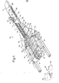
- FIGURE 1 is a schematic perspective view of a packaging machine according to the invention, and
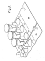
- FIGURE 2 is a perspective view showing the relative spacing arrangement between wrapper blanks and containers.
- Referring to the drawings, a
packaging machine 10 comprises an infeedsection 12 having a hopper 14 holding a stack 's' of wrapper blanks 'b'. The blanks are successively withdrawn from the hopper by a timedwithdrawal mechanism 16 and deposited on a wrapper infeedconveyor 18. The infeedconveyor 18 comprises endless belts such as chains (not shown) which incorporate upstanding lugs 'L' which engage in recesses 'r' formed in the leading and trailing edges of the wrapper blanks 'b', in the top wall panels of the wrapper. - Each blank is thus fed forwardly in substantially flat condition by a pair of the chain lugs 'L' pushing against the trailing edge of the blank towards a
loading section 20 of the machine. The position of the lugs 'L' may be altered to accomodate blanks of a different width. - As best seen in FIGURE 2, the base panel 'p' of each blank has a pair of parallel rows of apertures 'a' each sized to receive a container 'c'. The spacing of one blank 'bl' from the next succeeding blank 'bt' is fixed by the positioning of the chain lugs 'L' so that the distance between the trailing aperture 'a3' of the blank 'bl' to the leading aperture 'al' of the blank 'bt' is equal to the distance between the apertures in the blanks themselves. Hence, the spacing of the apertures 'a' is as in a continuous web of material having equi-distant spaced apertures.
- As the blanks are fed forwardly, an ejector device (not shown) located below the infeed
conveyor 18 and which comprises a rotatable element having radially projecting fingers, presses out reinforcing tabs 't' from the plane of the blank into an upstanding position as shown with reference to blanks 'b2' and 'b3' in FIGURE 1. - The wrapper infeed
conveyor 18 is flanked on each of its sides by parallel container infeedconveyors supply conveyor 26 upstream of the infeed section by passing through a knowncontainer separator device 28 comprising counter-rotating star wheels W', W2. As the two rows of containers 'c' are fed forwardly on their respective conveyors they are constrained to move inwardly on convergent paths by guide bars 'g' mounted aboveconveyors 22 and 24, and the bases of the containers slide along a fixed support bar 'R' located between and below the guide bars 'g'. As the containers leave their respective infeed conveyors and onto the support bar R, they are engaged by spacer elements 'e' carried byendless belts 30 and 32 respectively, which maintain the containers upright and feed the containers along their respective support bars in convergent paths in spaced relationship inwardly and above the wrapper blanks into theloading section 20 of the machine. The containers 'c' are held spaced apart by the spacer elements 'e' such that the distance between successive containers is equal to the distance between successive apertures 'a' in the wrapper blanks (see FIGURE 2). As the containers enter theloading section 20, as shown at the position of wrapper blank b4, they move directly above the blank b4 and are brought into parallel alignment longitudinally of the feed direction. The timing of the blank feed and of the container feed is synchronised so that successive containers are positioned above successive apertures of the blank. The downstream end of the wrapper infeed conveyor is downwardly inclined approximately 5° to the horizontal to allow clearance of the chain lugs 'L' to pass beneath the convergent container feed paths so that the blanks (see blank b3) are temporarily displaced downwardly. The leading edge of wrapper 'b4' begins to be displaced upwardly from its horizontal feed path by a ramp surface below the wrappers in the loading section and the leading apertures 'a' of blank 'b4' therefore receive the bases of the containers positioned thereabove. The ramp surface is provided by upwardly inclined static guides 'Sg' beneath the wrapper blanks. - This position corresponds to the outfeed end of the wrapper infeed conveyor at which the lugs 'L' disengage from the trailing edge of wrapper b4 and pass back along the return path of the conveyor to the upstream end of the infeed section.
- The support bars on which the container bases are seated terminate immediately prior to the location at which the containers begin to be received in the blank apertures. Movement of the wrapper blanks up the static guide ramp surface is imparted by the containers engaged in the blank apertures and which themselves are moved by the spaced elements.
- Parallel
movable friction belts friction belts outfeed conveyor 38 which extends beneath the friction belts from the position of blank B5 to the outfeed end of the machine an dhwihc continues the forward feed of the mated wrappers and containers together with the forward feed imparted byfriction belt conveyors - At the outfeed end of the machine the side panels of the wrappers engage fixed guides (not shown) positioned in the path of movement of the wrappers so that they are folded into upright position from the position of wrapper blank 'b6' to the position of wrapper blank 'b7'. Further fixed guides cause the reinforcing tabs 't' to be folded into a flat position overlying the tops of the containers in their respective rows as shown at the position of blank 'b8'.
- Also at the position of blank 'b8' an application of glue is made by
glue guns 40 to both the exposed top surfaces of the reinforcing tabs 't' and to the inner top wall 'ti' of the wrapper, whereafter the inner top wall 'ti' is folded inwardly into horizontal position. At this time forward feed of the partially formed package is augmented by side wall engagingfriction belts - The main top panel 'tm' of the wrapper is then caused to be folded downwardly by guide elements (not shown) into face contacting relationship with inner top panel 'ti' as at position 'b9'. Thereafter, the package 'P' passes beneath a pressure belt (not shown) to ensure good adhesive contact between the glued panels.
- It is to be understood that whereas the above description relates to a double line loading construction, a suitably modified arrangement may provide for a single line of containers to be loaded.
Claims (7)
Applications Claiming Priority (2)
| Application Number | Priority Date | Filing Date | Title |
|---|---|---|---|
| GB8333706 | 1983-12-19 | ||
| GB838333706A GB8333706D0 (en) | 1983-12-19 | 1983-12-19 | Packaging machine method |
Publications (3)
| Publication Number | Publication Date |
|---|---|
| EP0149351A2 true EP0149351A2 (en) | 1985-07-24 |
| EP0149351A3 EP0149351A3 (en) | 1985-08-14 |
| EP0149351B1 EP0149351B1 (en) | 1988-09-07 |
Family
ID=10553479
Family Applications (1)
| Application Number | Title | Priority Date | Filing Date |
|---|---|---|---|
| EP84308922A Expired EP0149351B1 (en) | 1983-12-19 | 1984-12-19 | Packaging machine and method |
Country Status (6)
| Country | Link |
|---|---|
| US (1) | US4571923A (en) |
| EP (1) | EP0149351B1 (en) |
| JP (1) | JPS60193812A (en) |
| DE (1) | DE3473864D1 (en) |
| ES (1) | ES8605429A1 (en) |
| GB (1) | GB8333706D0 (en) |
Cited By (9)
| Publication number | Priority date | Publication date | Assignee | Title |
|---|---|---|---|---|
| WO1988004259A1 (en) * | 1986-12-06 | 1988-06-16 | Bonar Cooke Cartons Limited | Carton packaging machine |
| EP0315065A1 (en) * | 1987-10-31 | 1989-05-10 | 4P Nicolaus Kempten GmbH | Apparatus for setting up a carrier |
| DE3740920A1 (en) * | 1987-12-03 | 1989-06-15 | Unilever Nv | DEVICE FOR UPRATING A FOLDING BOX CUT |
| EP0367674A1 (en) * | 1988-10-31 | 1990-05-09 | L'emballage Carton S.A. | Method for packaging objects, and machine for carrying out this method |
| WO1990013486A1 (en) * | 1989-04-28 | 1990-11-15 | Bonar Cooke Cartons Limited | Machine for forming a package from a blank |
| FR2653745A2 (en) * | 1988-10-31 | 1991-05-03 | Emballage Carton Sa | Method for packaging objects and machine for implementing this method |
| US5154039A (en) * | 1990-07-13 | 1992-10-13 | Pascal De Guglielmo | Packing method and machine |
| US5197260A (en) * | 1988-10-31 | 1993-03-30 | L Emballage Carton Sa (Societe Anonyme) | Method for packing articles, and machine for performing the method |
| GB2604200A (en) * | 2020-09-07 | 2022-08-31 | Keymac USA LLC | Improvements in or relating to packaging |
Families Citing this family (16)
| Publication number | Priority date | Publication date | Assignee | Title |
|---|---|---|---|---|
| US4901501A (en) * | 1988-11-18 | 1990-02-20 | Standard Knapp, Inc. | Continuous motion container packer for use with trays having pockets for such containers |
| GB9413864D0 (en) * | 1994-07-08 | 1994-08-24 | Mead Corp | Packaging machinery |
| GB2357273B (en) * | 1999-12-17 | 2002-01-09 | Buralls Of Wisbech Ltd | Method and apparatus for product packaging |
| US7316103B2 (en) * | 2006-06-05 | 2008-01-08 | Graphic Packaging International, Inc. | Continuous motion packaging system |
| AU2012200571B2 (en) * | 2006-11-07 | 2014-07-24 | Graphic Packaging International, Llc | Packages and packaging system |
| MX2009004743A (en) * | 2006-11-07 | 2009-05-22 | Graphic Packaging Int Inc | Packages and packaging system. |
| GB0801889D0 (en) * | 2008-02-01 | 2008-03-12 | Meadwestvaco Packaging Systems | Twin packaging line and metering system |
| FR2954285B1 (en) * | 2009-12-22 | 2012-02-03 | Automatisation Et Renovation Du Conditionnement Dans Les Ind Laitieres Arcil | METHOD AND MACHINE FOR OVERPACKING ARTICLES FOR FORMING LOTS OF ARTICLES, OF THE TYPE COMPRISING A SINGLE PLURALITY OF ARTICLES AND A CARDBOARD OVERPACK. |
| ES2923890T3 (en) | 2011-05-06 | 2022-10-03 | Graphic Packaging Int Llc | Cardboard box with characteristic item protection feature |
| WO2013059546A1 (en) | 2011-10-19 | 2013-04-25 | Graphic Packaging International, Inc. | System and method for activating article protection features of a carton |
| US9840358B2 (en) | 2013-03-14 | 2017-12-12 | Graphic Packaging International, Inc. | Carton with article protection feature |
| AU2014251065B2 (en) | 2013-04-10 | 2017-08-24 | Graphic Packaging International, Llc | Carton with article protection feature |
| US9701436B2 (en) | 2013-04-10 | 2017-07-11 | Graphic Packaging International, Inc. | Carton with article protection feature |
| CN105644835B (en) * | 2016-03-31 | 2017-12-08 | 青岛德隆科技有限公司 | Full-automatic six bags packaging integrated machine |
| CN108945591A (en) * | 2018-07-12 | 2018-12-07 | 佛山市舜富文具有限公司 | A kind of coloured silk mud cup automatic packaging packaging facilities |
| AU2022297372A1 (en) * | 2021-06-22 | 2024-01-18 | Westrock Packaging Systems, Llc | Packaging |
Citations (4)
| Publication number | Priority date | Publication date | Assignee | Title |
|---|---|---|---|---|
| US2817196A (en) * | 1954-01-14 | 1957-12-24 | Gardner Board & Carton Co | Can packaging machine |
| US3016663A (en) * | 1957-02-04 | 1962-01-16 | George B Holmes | Machine for packaging cylindrical objects |
| US3032945A (en) * | 1959-02-05 | 1962-05-08 | Container Corp | Can packing apparatus |
| US3805478A (en) * | 1973-01-12 | 1974-04-23 | Anderson Bros Mfg Co | Tray loading apparatus |
Family Cites Families (8)
| Publication number | Priority date | Publication date | Assignee | Title |
|---|---|---|---|---|
| US2817197A (en) * | 1956-02-03 | 1957-12-24 | Gardner Board & Carton Co | Can packaging apparatus |
| US3543474A (en) * | 1968-08-26 | 1970-12-01 | Container Corp | Gusset forming machine |
| US3827211A (en) * | 1973-01-02 | 1974-08-06 | Federal Paper Board Co Inc | Packaging machine |
| FR2250342A5 (en) * | 1973-11-05 | 1975-05-30 | Volume H B Sarl | Packaging to hold together pots, containers etc. - has a base with holes for pots and a lid which folds over the top |
| US3956868A (en) * | 1974-11-06 | 1976-05-18 | Federal Paper Board Company, Inc. | Carton opening, filling and closing apparatus |
| US4091937A (en) * | 1976-10-08 | 1978-05-30 | The Mead Corporation | Apparatus for setting up and loading a tray |
| US4188766A (en) * | 1978-11-22 | 1980-02-19 | The Mead Corporation | Packaging machine |
| FR2521100A1 (en) * | 1982-01-22 | 1983-08-12 | Mead Corp | Packager for conical articles - has feed to fold moving blank onto two converging files of articles below it |
-
1983
- 1983-12-19 GB GB838333706A patent/GB8333706D0/en active Pending
-
1984
- 1984-11-19 US US06/683,746 patent/US4571923A/en not_active Expired - Lifetime
- 1984-12-18 ES ES538764A patent/ES8605429A1/en not_active Expired
- 1984-12-18 JP JP59267276A patent/JPS60193812A/en active Granted
- 1984-12-19 DE DE8484308922T patent/DE3473864D1/en not_active Expired
- 1984-12-19 EP EP84308922A patent/EP0149351B1/en not_active Expired
Patent Citations (4)
| Publication number | Priority date | Publication date | Assignee | Title |
|---|---|---|---|---|
| US2817196A (en) * | 1954-01-14 | 1957-12-24 | Gardner Board & Carton Co | Can packaging machine |
| US3016663A (en) * | 1957-02-04 | 1962-01-16 | George B Holmes | Machine for packaging cylindrical objects |
| US3032945A (en) * | 1959-02-05 | 1962-05-08 | Container Corp | Can packing apparatus |
| US3805478A (en) * | 1973-01-12 | 1974-04-23 | Anderson Bros Mfg Co | Tray loading apparatus |
Cited By (13)
| Publication number | Priority date | Publication date | Assignee | Title |
|---|---|---|---|---|
| GB2220403B (en) * | 1986-12-06 | 1991-03-06 | Bonar Cooke Cartons Ltd | Carton packaging machine |
| WO1988004259A1 (en) * | 1986-12-06 | 1988-06-16 | Bonar Cooke Cartons Limited | Carton packaging machine |
| GB2220403A (en) * | 1986-12-06 | 1990-01-10 | Bonar Cooke Cartons Ltd | Carton packaging machine |
| US5033255A (en) * | 1986-12-06 | 1991-07-23 | Bonar Cooke Cartons Limited | Carton packaging machine |
| EP0315065A1 (en) * | 1987-10-31 | 1989-05-10 | 4P Nicolaus Kempten GmbH | Apparatus for setting up a carrier |
| DE3737034A1 (en) * | 1987-10-31 | 1989-05-11 | Unilever Nv | DEVICE FOR RISING UP A CARRIER |
| DE3740920A1 (en) * | 1987-12-03 | 1989-06-15 | Unilever Nv | DEVICE FOR UPRATING A FOLDING BOX CUT |
| FR2653745A2 (en) * | 1988-10-31 | 1991-05-03 | Emballage Carton Sa | Method for packaging objects and machine for implementing this method |
| EP0367674A1 (en) * | 1988-10-31 | 1990-05-09 | L'emballage Carton S.A. | Method for packaging objects, and machine for carrying out this method |
| US5197260A (en) * | 1988-10-31 | 1993-03-30 | L Emballage Carton Sa (Societe Anonyme) | Method for packing articles, and machine for performing the method |
| WO1990013486A1 (en) * | 1989-04-28 | 1990-11-15 | Bonar Cooke Cartons Limited | Machine for forming a package from a blank |
| US5154039A (en) * | 1990-07-13 | 1992-10-13 | Pascal De Guglielmo | Packing method and machine |
| GB2604200A (en) * | 2020-09-07 | 2022-08-31 | Keymac USA LLC | Improvements in or relating to packaging |
Also Published As
| Publication number | Publication date |
|---|---|
| US4571923A (en) | 1986-02-25 |
| JPH0567488B2 (en) | 1993-09-27 |
| ES8605429A1 (en) | 1986-03-16 |
| DE3473864D1 (en) | 1988-10-13 |
| EP0149351A3 (en) | 1985-08-14 |
| ES538764A0 (en) | 1986-03-16 |
| GB8333706D0 (en) | 1984-01-25 |
| JPS60193812A (en) | 1985-10-02 |
| EP0149351B1 (en) | 1988-09-07 |
Similar Documents
| Publication | Publication Date | Title |
|---|---|---|
| EP0149351A2 (en) | Packaging machine and method | |
| US4443995A (en) | Metering device and method | |
| US5996310A (en) | Packaging apparatus | |
| US4642967A (en) | Packaging machine | |
| US5214901A (en) | Apparatus and method for inserting a spacer between two packs of cigarettes | |
| JPH03501013A (en) | Equipment for separating and loading products | |
| CZ279197A3 (en) | Packaging machine for multiple packaging | |
| US20030000182A1 (en) | Packaging machine and apparatus for wraparound cartons | |
| US5469687A (en) | Apparatus for forming stacked article groups utilizing clip-type carriers | |
| US5481848A (en) | Method for feeding and preparing information leaflets on a product packaging line and a system for implementing this method | |
| US3031813A (en) | Method and machine for applying dividers to bottles | |
| KR100600927B1 (en) | Article grouping mechanism | |
| US4854108A (en) | Automatic wrapping machine | |
| US5309697A (en) | Chewing gum packaging machine | |
| EP0004744B1 (en) | Apparatus for forming packages | |
| CN111989268B (en) | Packaging machine | |
| US2919526A (en) | Can packaging machine | |
| EP0092402A2 (en) | Improved carton packing apparatus | |
| EP0717702B1 (en) | Method of forming stacked article groups into packages | |
| EP0802875B1 (en) | Packaging machinery | |
| JP4146261B2 (en) | Packaging equipment | |
| EP0161784B1 (en) | Drop-loading packaging machine | |
| JPS59124619A (en) | Distribution/alignment device of transported articles | |
| EP1240082A1 (en) | Packaging machine and apparatus for tightening wraparound cartons |
Legal Events
| Date | Code | Title | Description |
|---|---|---|---|
| PUAI | Public reference made under article 153(3) epc to a published international application that has entered the european phase |
Free format text: ORIGINAL CODE: 0009012 |
|
| PUAL | Search report despatched |
Free format text: ORIGINAL CODE: 0009013 |
|
| AK | Designated contracting states |
Designated state(s): BE DE FR GB IT LU NL |
|
| AK | Designated contracting states |
Designated state(s): BE DE FR GB IT LU NL |
|
| 17P | Request for examination filed |
Effective date: 19860213 |
|
| 17Q | First examination report despatched |
Effective date: 19860714 |
|
| D17Q | First examination report despatched (deleted) | ||
| GRAA | (expected) grant |
Free format text: ORIGINAL CODE: 0009210 |
|
| AK | Designated contracting states |
Kind code of ref document: B1 Designated state(s): BE DE FR GB IT LU NL |
|
| REF | Corresponds to: |
Ref document number: 3473864 Country of ref document: DE Date of ref document: 19881013 |
|
| ET | Fr: translation filed | ||
| ITF | It: translation for a ep patent filed |
Owner name: SOCIETA' ITALIANA BREVETTI S.P.A. |
|
| PG25 | Lapsed in a contracting state [announced via postgrant information from national office to epo] |
Ref country code: LU Free format text: LAPSE BECAUSE OF NON-PAYMENT OF DUE FEES Effective date: 19881231 |
|
| PLBE | No opposition filed within time limit |
Free format text: ORIGINAL CODE: 0009261 |
|
| STAA | Information on the status of an ep patent application or granted ep patent |
Free format text: STATUS: NO OPPOSITION FILED WITHIN TIME LIMIT |
|
| 26N | No opposition filed | ||
| ITTA | It: last paid annual fee | ||
| REG | Reference to a national code |
Ref country code: GB Ref legal event code: IF02 |
|
| PGFP | Annual fee paid to national office [announced via postgrant information from national office to epo] |
Ref country code: FR Payment date: 20031110 Year of fee payment: 20 |
|
| PGFP | Annual fee paid to national office [announced via postgrant information from national office to epo] |
Ref country code: NL Payment date: 20031117 Year of fee payment: 20 |
|
| PGFP | Annual fee paid to national office [announced via postgrant information from national office to epo] |
Ref country code: GB Payment date: 20031118 Year of fee payment: 20 |
|
| PGFP | Annual fee paid to national office [announced via postgrant information from national office to epo] |
Ref country code: DE Payment date: 20031125 Year of fee payment: 20 |
|
| PGFP | Annual fee paid to national office [announced via postgrant information from national office to epo] |
Ref country code: BE Payment date: 20031217 Year of fee payment: 20 |
|
| PG25 | Lapsed in a contracting state [announced via postgrant information from national office to epo] |
Ref country code: GB Free format text: LAPSE BECAUSE OF EXPIRATION OF PROTECTION Effective date: 20041218 |
|
| PG25 | Lapsed in a contracting state [announced via postgrant information from national office to epo] |
Ref country code: NL Free format text: LAPSE BECAUSE OF EXPIRATION OF PROTECTION Effective date: 20041219 |
|
| BE20 | Be: patent expired |
Owner name: THE *MEAD CORP. Effective date: 20041219 |
|
| REG | Reference to a national code |
Ref country code: GB Ref legal event code: PE20 |
|
| NLV7 | Nl: ceased due to reaching the maximum lifetime of a patent |
Effective date: 20041219 |