EP0149050A2 - Facsimile transmission system - Google Patents
Facsimile transmission system Download PDFInfo
- Publication number
- EP0149050A2 EP0149050A2 EP84113739A EP84113739A EP0149050A2 EP 0149050 A2 EP0149050 A2 EP 0149050A2 EP 84113739 A EP84113739 A EP 84113739A EP 84113739 A EP84113739 A EP 84113739A EP 0149050 A2 EP0149050 A2 EP 0149050A2
- Authority
- EP
- European Patent Office
- Prior art keywords
- pels
- pel
- amplitude
- gii
- conversion table
- Prior art date
- Legal status (The legal status is an assumption and is not a legal conclusion. Google has not performed a legal analysis and makes no representation as to the accuracy of the status listed.)
- Granted
Links
Images


Classifications
-
- H—ELECTRICITY
- H04—ELECTRIC COMMUNICATION TECHNIQUE
- H04N—PICTORIAL COMMUNICATION, e.g. TELEVISION
- H04N1/00—Scanning, transmission or reproduction of documents or the like, e.g. facsimile transmission; Details thereof
- H04N1/41—Bandwidth or redundancy reduction
- H04N1/411—Bandwidth or redundancy reduction for the transmission or storage or reproduction of two-tone pictures, e.g. black and white pictures
- H04N1/413—Systems or arrangements allowing the picture to be reproduced without loss or modification of picture-information
- H04N1/4135—Systems or arrangements allowing the picture to be reproduced without loss or modification of picture-information in which a baseband signal showing more than two values or a continuously varying baseband signal is transmitted or recorded
-
- H—ELECTRICITY
- H04—ELECTRIC COMMUNICATION TECHNIQUE
- H04N—PICTORIAL COMMUNICATION, e.g. TELEVISION
- H04N1/00—Scanning, transmission or reproduction of documents or the like, e.g. facsimile transmission; Details thereof
- H04N1/41—Bandwidth or redundancy reduction
- H04N1/411—Bandwidth or redundancy reduction for the transmission or storage or reproduction of two-tone pictures, e.g. black and white pictures
- H04N1/413—Systems or arrangements allowing the picture to be reproduced without loss or modification of picture-information
- H04N1/415—Systems or arrangements allowing the picture to be reproduced without loss or modification of picture-information in which the picture-elements are subdivided or grouped into fixed one-dimensional or two-dimensional blocks
Landscapes
- Engineering & Computer Science (AREA)
- Multimedia (AREA)
- Signal Processing (AREA)
- Facsimile Scanning Arrangements (AREA)
- Facsimile Transmission Control (AREA)
Abstract
Description
- The invention relates to a method -and apparatus for transmitting and receiving data representing elements of an image (PELs), in which the size of said PELs is smaller than the size of PELs being transmitted.
- The vestigial side band amplitude modulation-phase modulation (AM-PM-VSB) has been recommended by C.C.I.T.T. for a facsimile transmission mode for the so-called GII mode facsimile terminal. The AM-PM-VSB uses an amplitude modulation which modulates the amplitude of a carrier signal in accordance with the amplitude of an input signal, and a phase modulation which inverts the phase when the amplitude of the input signal is equal to zero, the vestigial side-band (VSB) method being used for transmission.
- Digital facsimile terminals which are capable of operating in both GII mode and the so-called GIII mode have been recently developed. Scan density in the GII mode, i.e. the number of scan lines per mm in a sub-scan or vertical direction, is 3.85 lines/mm, and scan density in the GIII mode is 7.7 lines/mm. The GII/GIII digital facsimile terminal has a scanner unit which includes a large number of scanning elements arranged in a line along a main scan or horizontal direction. Typical device used as the scanner unit is CCD (Charge Coupled Device) scanner unit. To accomodate the GIII operational mode with the scan density of 7.7 scan lines/mm, CCD elements are horizontally arranged with a density of 8 elements/mm, thus each CCD element defines one PEL of

- In the known facsimile terminal, amplitude signals from the CCD elements representing the amount of reflected light from the original document are processed by the terminal. In the GIII mode, the facsimile terminal handles the

- In the GIII mode facsimile operation, all PELs, i.e. P11, P12, P13 ....., P21, P22, P23, ...., P31, P32, P33...., and P41, P42, P43 ...., are transmitted from the transmitter facsimile terminal to the receiver facsimile terminal through a transmission line. The receiver facsimile terminal reproduces all PELs, P11' P12, P13' ...., P21, P22, P23,...., etc. of the original facsimile document. For the GII mode facsimile operation, PEL size is defined as

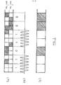
PEL line 1 andPEL line 2, which is detected by the scanner unit is shown. PEL size in the GII mode operation is shown by thick lines which form large GII mode PELs. Each GII mode PEL contains four GIII mode PELs. First, second, fourth and fifth GII mode PELs are determined as white level,i.e. binary 1, while third, sixth and seventh GII mode PELs are determined as black level,i.e. binary 0, due to the decision by majority. The waveform of the transmitted signal is shown in (b) of Fig. 2. The amplitude of the carrier signal is modulated in accordance with the determined binary values for each GII PEL. The reproduced image at the receiver facsimile terminal is shown in (c) of Fig. 2. Comparing the reproduced image (c) with the scanned_image (a) of Fig. 2, it is apparent that the reproduced image in the GII mode operation lacks the details of the scanned image, in spite of that the scanner unit provides the detailed GIII PEL image, (a) of Fig. 2. - The invention resolves the above problem by transmitting the detailed GIII PEL information which was lost in the above prior technology, through the GII transmission line. The image is transmitted through the transmission line using AM-PM-VSB of the GII mode and correctly reproduces the scanned PEL images (a) of Fig. 2 at the receiver facsimile terminal.
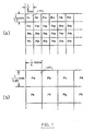
- The large size PELs, e.g. Pa, Pb" etc., are GII PELs of the GII transmission mode using AM-PM-VSB, and the scanned PELs, e.g. P11, P12, etc., are small size PELs which are PELs of higher density than that of the GII transmission mode using AM-PM-VSB. It is also noted that although the GII PEL is shown in Fig. 1 as having four GIII mode PELs, the PELs of the transmission mode using AM-PM-VSB could include more GIII PELs than four, such as nine PELs, sixteen PELs, etc.
- The method according to the invention is characterized in
claim 1. - Thus, while using a large size PEL transmission system, the resolution into small size PELs at the receiver is maintained.
-
- Fig. la shows small size PELs, and
- Fig. lb shows large size PELs, including a number of small size PELs.
- Fig. 2 shows the transmission and the reproduction of a small size PEL image through the prior transmission system.
- Fig. 3 shows the block diagram for a transmitter facsimile terminal.
- Fig. 4 shows the waveform modulated in accordance with the invention for transmitting the high density PEL image.
- Fig. 5 shows the assignment of sixteen sub-ranges of the carrier amplitude to the sixteen combinations of white or black small size PELs in the sample window, respectively, and
- Fig. 6 shows the block diagram for a receiver - facsimile terminal.
- Referring to Fig. 3, block diagram of a transmitter facsimile terminal is shown in which a
document 2 is moved across ascanner unit 1, e.g. CCD scanner unit.Successive PEL lines 3 are scanned during the movement of thedocument 2. Thescanner unit 1 detects the light reflected from thedocument 2 with the high PEL density or resolution of the GIII mode, i.e.
binary signals parallel conversion circuit 4, which converts the input serial data to a parallel data and supplies the parallel data to buffer 5. - The two
PEL line buffer 5 stores PEL data of two consecutive PEL lines. An example of the two PEL line data stored in the twoPEL line buffer 5 is shown in (a) of Fig. 4, which is selected to be the same as that shown in (a) of Fig. 2, for the sake of understanding the invention. - The sample window 21 (Fig. 4) is set up by
address pointer 6. The size of thesample window 21 is selected to be equal to the PEL size of the GII transmission mode, i.e.
- The first sample window
samples PEL group 1, second sample windowsamples PEL group 2, third sample windowsamples PEL group 3, and so on. Theaddress pointer 6 sequentially addresses the appropriate four bit positions in the twoPEL line buffer 5 to shift the sample window through the PEL groups inbuffer 5. - The four bits enclosed by the
sample window 21 are used to access a conversion table 7. The four bits in the sample window represent sixteen combinations of the positions of white or black PELs in one window, as shown in Fig. 5. The conversion table 7 stores sixteen values or entries (A) - (P) which represent the degree of amplitude modulation of the carrier signal. - Describing the amplitude modulation, the output signal in the GII mode varies between 0 dB and -26 dB, and 0 dB signal could be deemed as white signal and -26 dB signal could be deemed as black signal, in accordance with C.C.I.T.T. proposal T3. In this embodiment, the
range 0 dB to -15 dB is selected. Therange 0 dB to -15 dB is equally divided into the sixteen sub-ranges, and these sixteen sub-ranges are shown in the Fig. 5 as entries (A) - (P). The sixteen combinations of four white or black PELs, as described above, are assigned to the sixteen sub-ranges, respectively, as shown in Fig. 5. - Returning to the Fig. 4, the
PEL group 1 has all white bits. These four bits "1111" are supplied to the conversion table 7 to access the entry (A), shown in the Fig. 5, which indicates "0 dB", which is applied toGII modulator 8 to control the degree of the amplitude modulation of the carrier signal to "0 dB". ThePEL group 2 is used to control the degree of the amplitude modulation to "-1 dB", and so on, as shown in (b) of the Fig. 4. - As apparent from the above description, the transmitter terminal modulates the amplitude of the transmitted carrier signal, in accordance with-the bit combination sampled by the
sample window 21, i.e. the distribution status or the position of black or white small size PELs enclosed by thesample window 21. - Referring to Fig. 6, a block diagram of the receiver facsimile terminal is shown. The transmitted signal with the amplitude modulation as shown in (b) of the Fig. 4 is supplied to
GII demodulator 31. TheGII demodulator 31 detects the amplitude of the received signal and produces a signal representing one of sixteen levels at its output in accordance with the detected amplitude of the received signal. For instance, a four bit signal is produced. The signal is applied to reverse conversion table 32,'which stores sixteen PEL groups as shown in Fig. 5, and is used to fetch one of the sixteen PEL groups. The PEL groups sequentially supplied by table 32 are assembled in twoPEL line buffer 33 under the control ofaddress pointer 34, so that the two PEL lines of the original document image shown in (a) of the Fig. 4 are reproduced in the 2PEL line buffer 33. Theaddress pointer 34 sequentially addresses bit positions in the twoPEL line buffer 33 to sequentially store the four bit-PEL groups received from the reverse conversion table 32 into the twoPEL line buffer 33. The assembled two PEL lines are supplied toprinter 36 through parallel-serial conversion circuit 35 to print the original document image on a recording sheet. - For the sake of the understanding of the invention, the
exemplary range 0 dB to -15 dB has been described. Taking into account noise problem in the transmission line, another range, such as -3dB to -18dB, -4dB to -19dB, could be used.
Claims (6)
Applications Claiming Priority (2)
| Application Number | Priority Date | Filing Date | Title |
|---|---|---|---|
| JP58218870A JPS60114088A (en) | 1983-11-22 | 1983-11-22 | Method of transmitting gii-giii mode |
| JP218870/83 | 1983-11-22 |
Publications (3)
| Publication Number | Publication Date |
|---|---|
| EP0149050A2 true EP0149050A2 (en) | 1985-07-24 |
| EP0149050A3 EP0149050A3 (en) | 1987-09-23 |
| EP0149050B1 EP0149050B1 (en) | 1990-08-08 |
Family
ID=16726590
Family Applications (1)
| Application Number | Title | Priority Date | Filing Date |
|---|---|---|---|
| EP84113739A Expired EP0149050B1 (en) | 1983-11-22 | 1984-11-14 | Facsimile transmission system |
Country Status (4)
| Country | Link |
|---|---|
| US (1) | US4686578A (en) |
| EP (1) | EP0149050B1 (en) |
| JP (1) | JPS60114088A (en) |
| DE (1) | DE3482950D1 (en) |
Cited By (1)
| Publication number | Priority date | Publication date | Assignee | Title |
|---|---|---|---|---|
| DE3706470A1 (en) * | 1986-07-30 | 1988-02-11 | Toshiba Kawasaki Kk | BINARY DATA COMPRESSION AND EXPANSION PROCESSING DEVICE |
Families Citing this family (4)
| Publication number | Priority date | Publication date | Assignee | Title |
|---|---|---|---|---|
| GB2235076B (en) * | 1989-08-17 | 1994-05-04 | Asahi Optical Co Ltd | Camera data communication method and camera |
| US5070532A (en) * | 1990-09-26 | 1991-12-03 | Radius Inc. | Method for encoding color images |
| US5247589A (en) * | 1990-09-26 | 1993-09-21 | Radius Inc. | Method for encoding color images |
| US5359432A (en) * | 1991-11-25 | 1994-10-25 | Lexmark International, Inc. | Printer page composition with color and text |
Citations (3)
| Publication number | Priority date | Publication date | Assignee | Title |
|---|---|---|---|---|
| GB2010643A (en) * | 1977-12-20 | 1979-06-27 | Oki Electric Ind Co Ltd | Facsimile transmission system |
| US4261018A (en) * | 1979-06-18 | 1981-04-07 | Bell Telephone Laboratories, Incorporated | Progressive image transmission |
| US4366505A (en) * | 1978-09-20 | 1982-12-28 | Canon Kabushiki Kaisha | Information forming apparatus |
Family Cites Families (3)
| Publication number | Priority date | Publication date | Assignee | Title |
|---|---|---|---|---|
| US3973079A (en) * | 1973-12-12 | 1976-08-03 | Hitachi, Ltd. | Two-level picture signal transmission system |
| US3893244A (en) * | 1974-07-15 | 1975-07-08 | Danford Jack D | Grain storage and shipping containers and method of using the same |
| JPS54150022A (en) * | 1978-05-18 | 1979-11-24 | Ricoh Co Ltd | Method and apparatus for picture encoding reproduction |
-
1983
- 1983-11-22 JP JP58218870A patent/JPS60114088A/en active Granted
-
1984
- 1984-11-14 EP EP84113739A patent/EP0149050B1/en not_active Expired
- 1984-11-14 DE DE8484113739T patent/DE3482950D1/en not_active Expired - Fee Related
- 1984-11-16 US US06/672,011 patent/US4686578A/en not_active Expired - Fee Related
Patent Citations (3)
| Publication number | Priority date | Publication date | Assignee | Title |
|---|---|---|---|---|
| GB2010643A (en) * | 1977-12-20 | 1979-06-27 | Oki Electric Ind Co Ltd | Facsimile transmission system |
| US4366505A (en) * | 1978-09-20 | 1982-12-28 | Canon Kabushiki Kaisha | Information forming apparatus |
| US4261018A (en) * | 1979-06-18 | 1981-04-07 | Bell Telephone Laboratories, Incorporated | Progressive image transmission |
Cited By (1)
| Publication number | Priority date | Publication date | Assignee | Title |
|---|---|---|---|---|
| DE3706470A1 (en) * | 1986-07-30 | 1988-02-11 | Toshiba Kawasaki Kk | BINARY DATA COMPRESSION AND EXPANSION PROCESSING DEVICE |
Also Published As
| Publication number | Publication date |
|---|---|
| EP0149050A3 (en) | 1987-09-23 |
| JPS60114088A (en) | 1985-06-20 |
| EP0149050B1 (en) | 1990-08-08 |
| JPH0149229B2 (en) | 1989-10-24 |
| US4686578A (en) | 1987-08-11 |
| DE3482950D1 (en) | 1990-09-13 |
Similar Documents
| Publication | Publication Date | Title |
|---|---|---|
| US4084196A (en) | Electronic half-tone generating means for facsimile reproduction system | |
| US4091424A (en) | Facsimile compression system | |
| US4905294A (en) | Image processing apparatus | |
| US4924509A (en) | Image processing apparatus | |
| US4698688A (en) | Image processing system | |
| US4571632A (en) | Alternate line interpolation method and apparatus | |
| US4517607A (en) | Method of and apparatus for compensating image in image reproduction system | |
| GB1573774A (en) | Facsimile compression system | |
| US3715475A (en) | Method and apparatus for electrically transmitting pictures | |
| US5452107A (en) | Image processing apparatus providing a bilevel image signal by changing binarization threshold value based on densities of original image areas incuding target pixel and less than all surrounding pixels | |
| US3775559A (en) | Aperture designs for facsimile scanning apparatus | |
| EP0149050B1 (en) | Facsimile transmission system | |
| US4996602A (en) | Image-processing apparatus | |
| JPS6043715B2 (en) | Narrowband still image transmission method | |
| US4298859A (en) | Digital video line delay circuit | |
| EP0336403B1 (en) | Image reading apparatus | |
| US5278672A (en) | Image signal processing apparatus | |
| EP0195925B1 (en) | Method for converting image gray levels | |
| GB2069797A (en) | Facsimile transmission system | |
| JPH0681243B2 (en) | Image processing method | |
| US5592303A (en) | Image communication apparatus and method which extracts and records images on the transmission side | |
| JPS58119269A (en) | Facsimile transmitter | |
| JPH0131344B2 (en) | ||
| JPH01282967A (en) | Gradation picture data processing system | |
| KR950006182B1 (en) | Picture processing device for fax |
Legal Events
| Date | Code | Title | Description |
|---|---|---|---|
| PUAI | Public reference made under article 153(3) epc to a published international application that has entered the european phase |
Free format text: ORIGINAL CODE: 0009012 |
|
| 17P | Request for examination filed |
Effective date: 19841211 |
|
| AK | Designated contracting states |
Designated state(s): DE FR GB |
|
| PUAL | Search report despatched |
Free format text: ORIGINAL CODE: 0009013 |
|
| RHK1 | Main classification (correction) |
Ipc: H04N 1/415 |
|
| AK | Designated contracting states |
Kind code of ref document: A3 Designated state(s): DE FR GB |
|
| 17Q | First examination report despatched |
Effective date: 19891115 |
|
| GRAA | (expected) grant |
Free format text: ORIGINAL CODE: 0009210 |
|
| AK | Designated contracting states |
Kind code of ref document: B1 Designated state(s): DE FR GB |
|
| REF | Corresponds to: |
Ref document number: 3482950 Country of ref document: DE Date of ref document: 19900913 |
|
| ET | Fr: translation filed | ||
| R20 | Corrections of a patent specification |
Effective date: 19900903 |
|
| PLBE | No opposition filed within time limit |
Free format text: ORIGINAL CODE: 0009261 |
|
| STAA | Information on the status of an ep patent application or granted ep patent |
Free format text: STATUS: NO OPPOSITION FILED WITHIN TIME LIMIT |
|
| 26N | No opposition filed | ||
| PGFP | Annual fee paid to national office [announced via postgrant information from national office to epo] |
Ref country code: GB Payment date: 19931019 Year of fee payment: 10 |
|
| PGFP | Annual fee paid to national office [announced via postgrant information from national office to epo] |
Ref country code: FR Payment date: 19931103 Year of fee payment: 10 |
|
| PGFP | Annual fee paid to national office [announced via postgrant information from national office to epo] |
Ref country code: DE Payment date: 19931118 Year of fee payment: 10 |
|
| PG25 | Lapsed in a contracting state [announced via postgrant information from national office to epo] |
Ref country code: GB Effective date: 19941114 |
|
| GBPC | Gb: european patent ceased through non-payment of renewal fee |
Effective date: 19941114 |
|
| PG25 | Lapsed in a contracting state [announced via postgrant information from national office to epo] |
Ref country code: FR Effective date: 19950731 |
|
| PG25 | Lapsed in a contracting state [announced via postgrant information from national office to epo] |
Ref country code: DE Effective date: 19950801 |
|
| REG | Reference to a national code |
Ref country code: FR Ref legal event code: ST |