EP0149046B1 - Anordnung zur Beeinflussung eines Schaltgerätes - Google Patents
Anordnung zur Beeinflussung eines Schaltgerätes Download PDFInfo
- Publication number
- EP0149046B1 EP0149046B1 EP84113644A EP84113644A EP0149046B1 EP 0149046 B1 EP0149046 B1 EP 0149046B1 EP 84113644 A EP84113644 A EP 84113644A EP 84113644 A EP84113644 A EP 84113644A EP 0149046 B1 EP0149046 B1 EP 0149046B1
- Authority
- EP
- European Patent Office
- Prior art keywords
- switched
- switching device
- processing stage
- phases
- current sensor
- Prior art date
- Legal status (The legal status is an assumption and is not a legal conclusion. Google has not performed a legal analysis and makes no representation as to the accuracy of the status listed.)
- Expired
Links
Images
Classifications
-
- H—ELECTRICITY
- H02—GENERATION; CONVERSION OR DISTRIBUTION OF ELECTRIC POWER
- H02H—EMERGENCY PROTECTIVE CIRCUIT ARRANGEMENTS
- H02H11/00—Emergency protective circuit arrangements for preventing the switching-on in case an undesired electric working condition might result
- H02H11/005—Emergency protective circuit arrangements for preventing the switching-on in case an undesired electric working condition might result in case of too low isolation resistance, too high load, short-circuit; earth fault
Definitions
- the invention relates to an arrangement for influencing a remote-controlled switching device in a multi-phase network as a function of network status data by means of an impedance measuring device, consisting of a measuring voltage source, at least one current sensor and a switching device and, when the switching device is not switched on, the switching device detects the measuring voltage from the measuring voltage source in Series with the current sensor and switches between the non-switched phases of the network and earth, the current sensor detects the impedance of the non-switched phases to earth and feeds it to a processing stage, and the processing stage blocks the switching device in the non-switched-on state when the value falls below a predetermined value of the impedance to earth .
- an impedance measuring device consisting of a measuring voltage source, at least one current sensor and a switching device and, when the switching device is not switched on, the switching device detects the measuring voltage from the measuring voltage source in Series with the current sensor and switches between the non-switched phases of the network and earth, the current sensor detects the imped
- the network status data are recorded after the switching device is switched on by current measurement in the form of bimetal elements which detect overcurrent and magnetic triggers which detect short-circuit current and, depending on the predetermined size, triggers the switching device. Accordingly, the switching device must be dimensioned for switching short-circuit currents on and off.
- the invention is intended to create a possibility of keeping the switching power of the switching device as low as possible and thus of making the switching device smaller and simpler.
- the switching device when the switching device is not switched on, the switching device also switches the measurement voltage from the measurement voltage source in series with the current sensor between the individual phases that are not switched on, the current sensor detects the impedances between the individual phases that are not switched on and supplies the processing stage and the processing stage blocks the switching device in the non-switched state when the value falls below a predetermined value of the impedance between the individual phases.
- the arrangement according to the invention is obtained practically without additional effort if, when assigning current sensors to each phase, the current sensors are used to detect the overload and / or short-circuit and / or operating currents, since this eliminates the need for the usual bimetal and magnetic short-circuit releases.
- the current sensors can also be used to display the operating currents. It is also advantageous if the current sensors are also used to detect overshoots. In order to be able to determine the reason why the switch-on was blocked or the switch-off took place, it is advantageous if the processing stage has outputs for operating status displays. In order to be able to carry out this detection as quickly as possible, it is furthermore advantageous if the processing stage is part of a microprocessor or microcomputer.
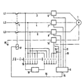
- a three-phase motor 1 is connected to the phases L1, L2, L3 and is switched on or off via the electromagnetic switching device 2.
- Current sensors 6, 7, 8, as are known per se, are switched on in the feed lines 3, 4, 5 to the motor 1.
- the measured current values are fed to a processing stage 9, for example a comparison circuit known per se, via lines 10, 11, 12 and 13.
- the line 13 is connected to the current sensor 14, which bsw the neutral conductor N.
- Protective conductor PE checked against the phases.
- the output 15 is connected via the line 16 to the actuating coil 17 of the electromagnetic switching device and, depending on the output command, can thus prevent the electromagnetic switching device from being switched on or, if the current values correspond, can switch the electromagnetic switching device off during operation.
- a defined measuring voltage from a measuring voltage source 18 is applied cyclically or simultaneously to the phases and the current sensors via a switching device 19, which can also be electronic 6 to 8 and 14 queried accordingly by processing stage 9. If predeterminable values of the impedances assigned to the corresponding network are undershot here, ie if there are short-circuit conditions, for example, the output 15 blocks the electromagnetic switching device 2 via the stage 17.
- the switching device 19 During operation, ie after the electromagnetic switching device 2 has been released, the switching device 19 is in the position shown in dashed lines, ie the measuring voltage 18 is ineffective and the connection of the phases to one another is removed, the current sensors 6 to 8 can be used via the processing stage 9 to detect overload or short-circuit currents occurring during operation or also measurement of harmonics, so that multiple use of the current sensors is possible, which further simplifies the switching device. Since the devices only have to have the short-circuit breaking capacity, their mechanics can be considerably simpler be carried out. The number of malfunctions is significantly reduced, since all malfunctions that are recognized before switching on can be eliminated without consequential damage to the system. Such faults can be tools left in the phase range or switching errors, for example.
Landscapes
- Emergency Protection Circuit Devices (AREA)
- Protection Of Generators And Motors (AREA)
Description
- Die Erfindung bezieht sich auf eine Anordnung zur Beeinflussung eines fernbetätigten Schaltgerätes in einem Mehrphasennetz in Abhängigkeit von Netzzustandsdaten mittels einer lmpedanzmeßeinrichtung, bestehend aus einer Meßspannungsquelle, zumindest einem Stromsensor und einer Schaltvorrichtung und wobei bei nicht eingeschaltetem Zustand des Schaltgerätes die Schaltvorrichtung die Meßspannung aus der Meßspannungsquelle in Reihe mit dem Stromsensor und zwischen die nicht eingechalteten Phasen des Netzes und Erde schaltet, der Stromsensor die Impedanz der nicht eingeschalteten Phasen gegen Erde erfaßt und einer Verarbeitungsstufe zuführt und die Verarbeitungsstufe beim Unterschreiten eines vorbestimmten Wertes der Impedanz gegen Erde das Schaltgerät im nicht eingeschalteten Zustand blockiert.
- Bei einer bekannten Anordnung der obengenannten Art (GB-A-1 035 328) ist zwar die Erfassung von Erdschlüssen in elektrischen Geräten möglich; das eigentliche Schaltgerät muß hier jedoch auch für eine Aufschaltung auf einen Kurzschluß dimensioniert werden.
- Bei weiterhin bekannten Schaltgeräten werden die Netzzustandsdaten nach dem Einschalten des Schaltgerätes durch Strommessung in Form von Überstrom erfassenden Bimetall-Elementen und Kurzschlußstrom erfassenden magnetischen Auslösern aufgenommen und je nach vorbestimmter Größe die Auslösung des Schaltgerätes bewirkt. Demnach muß das Schaltgerät für das Ein- und Ausschalten von Kurzschlußströmen bemessen sein. Durch die Erfindung soll eine Möglichkeit geschaffen werden, die Schaltleistung des Schaltgerätes möglichst gering zu halten und damit das Schaltgerät kleiner und einfacher ausführen zu können. Diese Aufgabe wird dadurch gelöst, daß bei nicht eingeschaltetem Zustand des Schaltgerätes die Schaltvorrichtung ferner die Meßspannung aus der Meßspannungsquelle in Reihe mit dem Stromsensor zwischen den einzelnen nicht eingeschalteten Phasen umschaltet, der Stromsensor die Impedanzen zwischen den einzelnen nicht eingeschalteten Phasen erfaßt und der Verarbeitungsstufe zuführt und die Verarbeitungsstufe beim Unterschreiten eines vorbestimmten Wertes der Impedanz zwischen den einzelnen Phasen das Schaltgerät im nicht eingeschalteten Zustand blockiert.
- Praktisch ohne Mehraufwand ergibt sich die erfindungsgemäße Anordnung, wenn bei Zuordnung von Stromsensoren zu jeder Phase die Stromsensoren zur Erfassung der Überlast-und/oder Kurzschluß- und/oder Betriebsströme mitbenutzt sind, da hierdurch die üblichen Bimetall- und magnetischen Kurzschlußauslöser entfallen können. Man kann die Stromsensoren zusätzlich auch zur Anzeige der Betriebsströme mitbenutzen. Weiter ist es von Vorteil, wenn die Stromsensoren zur Erfassung von Überschwingungen mitbenutzt sind. Um feststellen zu können, aus welchem Grund die Einschaltung blockiert oder die Ausschaltung erfolgte, ist es vorteilhaft, wenn die Verarbeitungsstufe Ausgänge für Betriebszustandsanzeigen hat. Um diese Erfassung möglichst schnell durchführen zu können ist es weitarhin von Vorteil, wenn die Verarbeitungsstufe Teil eines Mikroprozessors oder Mikrocomputers ist.
- Anhand der Zeichnung wird ein Ausführungsbeispiel gemäß der Erfindung schematisch dargestellt.
- An die Phasen L1, L2, L3 ist ein Drehstrommotor 1 angeschlossen, der über das elektromagnetische Schaltgerät 2 ein- oder ausgeschaltet wird. In den Zuleitungen 3, 4, 5 zum Motor 1 sind Stromsensoren 6, 7, 8 eingeschaltet, wie sie an sich bekannt sind. Die gemessenen Stromwerte werden einer Verarbeitungsstufe 9, beispielsweise einer an sich bekannten Vergleichsschaltung, über die Leitungen 10, 11, 12 und 13 zugeführt. Die Leitung 13 ist mit dem Stromsensor 14 in Verbindung gebracht, der die Neutralleiter N bsw. Schutzleiter PE gegenüber den Phasen überprüft. Der Ausgang 15 ist über die Leitung 16 an die Betätigungsspule 17 des elektromagnetischen Schaltgerätes angeschlossen und kann so, je nach Ausgangsbefehl, das Einschalten des elektromagnetischen Schaltgerätes verhindern oder aber bei entsprechenden Stromwerten während des Betriebes das elektromagnetische Schaltgerät ausschalten. Zum Messen der Impedanz in den einzelnen Phasen L1, L2, L3 und der Phasen gegen den Schutzleiter PE wird eine definierte Meßspannung aus einer Meßspannungsquelle 18 über eine Schaltvorrichtung 19, die auch elektronischer Art sein kann, zyklusmäßig oder gleichzeitig an die Phasen angelegt und die Stromsensoren 6 bis 8 und 14 durch die Verarbeitungsstufe 9 entsprechend abgefragt. Werden hier dem entsprechenden Netz zugeordnete, vorbestimmbare Werte der Impedanzen unterschritten, d. h. liegen beispielsweise Kurzschlußbedingungen vor, so blockiert der Ausgang 15 über die Stufe 17 das elektromagnetische Schaltgerät 2. Während des Betriebes, d. h. nach Freigabe des elektromagnetischen Schaltgerätes 2 befindet sich die Schaltvorrichtung 19 in der gestrichelt dargestellten Lage, d. h. die Meßspannung 18 ist unwirksam und die Verbindung der Phasen untereinander ist aufgehoben, so können die Stromsensoren 6 bis 8 über die Verarbeitungsstufe 9 zur Erfassung von während des Betriebes auftretenden Überlast- oder Kurzschlußströmen oder auch Messung von Oberschwingungen herangezogen werden, so daß eine Mehrfachausnutzung der Stromsensoren möglich ist, was das Schaltgerät weiterhin vereinfacht. Da die Geräte nur noch das Kurzschlußausschaltvermögen besitzen müssen, können sie in ihrer Mechanik erheblich einfacher ausgeführt werden. Die Zahl der Betriebsstörungen wird erheblich vermindert, da alle Störungen, die bereits vor dem Einschalten erkannt werden, ohne Folgeschäden für die Anlage beseitigt werden können. Derartige Störungen können beispielsweise im Phasenbereich liegengebliebene Werkzeuge oder Schaltfehler sein.
Claims (5)
Applications Claiming Priority (2)
| Application Number | Priority Date | Filing Date | Title |
|---|---|---|---|
| DE3347209 | 1983-12-27 | ||
| DE19833347209 DE3347209A1 (de) | 1983-12-27 | 1983-12-27 | Anordnung zur beeinflussung eines schaltgeraetes |
Publications (3)
| Publication Number | Publication Date |
|---|---|
| EP0149046A2 EP0149046A2 (de) | 1985-07-24 |
| EP0149046A3 EP0149046A3 (en) | 1985-08-07 |
| EP0149046B1 true EP0149046B1 (de) | 1988-06-29 |
Family
ID=6218234
Family Applications (1)
| Application Number | Title | Priority Date | Filing Date |
|---|---|---|---|
| EP84113644A Expired EP0149046B1 (de) | 1983-12-27 | 1984-11-12 | Anordnung zur Beeinflussung eines Schaltgerätes |
Country Status (3)
| Country | Link |
|---|---|
| EP (1) | EP0149046B1 (de) |
| JP (1) | JPS6356120A (de) |
| DE (2) | DE3347209A1 (de) |
Families Citing this family (7)
| Publication number | Priority date | Publication date | Assignee | Title |
|---|---|---|---|---|
| EP0222688A3 (de) * | 1985-11-08 | 1989-03-01 | Siemens Aktiengesellschaft | Einrichtung zur ferngesteuerten Veränderung von Auslösewerten eines Schaltgerätes und Verfahren zur Umrüstung eines Schaltgerätes |
| DE3626399A1 (de) * | 1986-08-04 | 1988-02-11 | Siemens Ag | Anordnung zur beeinflussung eines schaltgeraetes |
| US5459631A (en) * | 1991-03-28 | 1995-10-17 | Siemens Energy & Automation, Inc. | Electronic charging motor controller |
| DE4128618A1 (de) * | 1991-08-28 | 1993-03-04 | Siemens Ag | Analoge anordnung zur schnellen kurzschlussdetektion |
| DE4128619A1 (de) * | 1991-08-28 | 1993-03-04 | Siemens Ag | Anordnung zur schnellen erkennung von kurzschluessen |
| EP0563695B1 (de) * | 1992-03-31 | 1999-05-26 | Siemens Aktiengesellschaft | Verfahren und Anordnung zur Erkennung von Kurzschlüssen in Leitungsabzweigen von elektrischen Netzen |
| IT1264551B1 (it) * | 1993-08-02 | 1996-10-02 | Bticino Spa | Dispositivo di controllo e di protezione di un impianto elettrico |
Family Cites Families (5)
| Publication number | Priority date | Publication date | Assignee | Title |
|---|---|---|---|---|
| GB1035328A (en) * | 1963-11-21 | 1966-07-06 | Wallacetown Engineering Compan | Earth leakage protective device |
| FR1420279A (fr) * | 1965-01-12 | 1965-12-03 | Procédé et dispositif de protection pour appareil électrique, et notamment pour générateur et récepteur statique et tournant | |
| US3996499A (en) * | 1974-09-09 | 1976-12-07 | Westinghouse Electric Corporation | Zener diode effect on long acceleration module |
| US4351013A (en) * | 1980-04-15 | 1982-09-21 | Westinghouse Electric Corp. | Circuit interrupter with multiple display and parameter entry means |
| JPS5788817A (en) * | 1980-11-20 | 1982-06-02 | Mitsubishi Electric Corp | Load protecting device |
-
1983
- 1983-12-27 DE DE19833347209 patent/DE3347209A1/de not_active Withdrawn
-
1984
- 1984-11-12 DE DE8484113644T patent/DE3472508D1/de not_active Expired
- 1984-11-12 EP EP84113644A patent/EP0149046B1/de not_active Expired
- 1984-12-25 JP JP59281914A patent/JPS6356120A/ja active Pending
Also Published As
| Publication number | Publication date |
|---|---|
| JPS6356120A (ja) | 1988-03-10 |
| EP0149046A3 (en) | 1985-08-07 |
| EP0149046A2 (de) | 1985-07-24 |
| DE3347209A1 (de) | 1985-07-11 |
| DE3472508D1 (en) | 1988-08-04 |
Similar Documents
| Publication | Publication Date | Title |
|---|---|---|
| DE3114547C2 (de) | Trennschalter mit Übertemperatur-Auslöseeinrichtung | |
| EP2017867B1 (de) | Messvorrichtung zum Messen eines periodischen Analogsignals | |
| DE69509093T2 (de) | Modul zur verwendung eines miniatur lastschalters | |
| EP0156184A2 (de) | Zusatzbaustein für einen Leistungsschalter mit einem Arbeitsstromauslöser | |
| EP0750382B1 (de) | Stromerfassungsgerät zur Anbringung an einem stromdurchflossenen Leiter | |
| DE19739780B4 (de) | Drehstrommotor | |
| DE2133809C2 (de) | Schaltungsanordnung zum Anzeigen von Fehlern in Drehstrom-Hochspannungsnetzen | |
| EP1058283A2 (de) | Überwachungssystem für Niederspannungsschaltgeräte | |
| EP2526601B1 (de) | Elektronischer überstromauslöser für schutzschalter | |
| WO2000026934A1 (de) | Elektrische mikromechanische fehlerstromschutz-schalteinrichtung | |
| EP0149046A2 (de) | Anordnung zur Beeinflussung eines Schaltgerätes | |
| DE102004020045A1 (de) | Verfahren zum Ermitteln eines eine Abnutzung von Schaltkontakten eines Leistungsschalters angebenden Restschaltspiel-Wertes | |
| EP4367704B1 (de) | Schutzschaltgerät | |
| WO2002071600A2 (de) | Sicherheitsschaltvorrichtung | |
| DE3237800C2 (de) | Schutzeinrichtung für Asynchron-Motoren | |
| DE3114548C2 (de) | ||
| EP0641057B1 (de) | Verteilerssysteem für zwei oder mehrere elektrische Verbraucher | |
| DE3114213C3 (de) | Verfahren zum Betreiben eines Trennschalters | |
| DE2037390C3 (de) | Distanzschutz für vermaschte elektrische Netze | |
| DE4040359C2 (de) | Einrichtung zum Kurzschlußschutz | |
| DE3879641T2 (de) | Statischer Auslöser mit externer Versorgung. | |
| EP0349880A1 (de) | Einrichtung zum Schutz vor Fehlerströmen | |
| DE2732379A1 (de) | Geraet zur automatischen uebertragungssteuerung | |
| DE102012208120A1 (de) | Ladevorrichtung für Elektrofahrzeuge | |
| DE3800721C1 (de) |
Legal Events
| Date | Code | Title | Description |
|---|---|---|---|
| PUAI | Public reference made under article 153(3) epc to a published international application that has entered the european phase |
Free format text: ORIGINAL CODE: 0009012 |
|
| PUAL | Search report despatched |
Free format text: ORIGINAL CODE: 0009013 |
|
| AK | Designated contracting states |
Designated state(s): CH DE FR IT LI SE |
|
| AK | Designated contracting states |
Designated state(s): CH DE FR IT LI SE |
|
| 17P | Request for examination filed |
Effective date: 19850925 |
|
| 17Q | First examination report despatched |
Effective date: 19860610 |
|
| D17Q | First examination report despatched (deleted) | ||
| GRAA | (expected) grant |
Free format text: ORIGINAL CODE: 0009210 |
|
| AK | Designated contracting states |
Kind code of ref document: B1 Designated state(s): CH DE FR IT LI SE |
|
| REF | Corresponds to: |
Ref document number: 3472508 Country of ref document: DE Date of ref document: 19880804 |
|
| ET | Fr: translation filed | ||
| ITF | It: translation for a ep patent filed | ||
| PLBE | No opposition filed within time limit |
Free format text: ORIGINAL CODE: 0009261 |
|
| 26N | No opposition filed | ||
| ITTA | It: last paid annual fee | ||
| PGFP | Annual fee paid to national office [announced via postgrant information from national office to epo] |
Ref country code: SE Payment date: 19941116 Year of fee payment: 11 |
|
| PGFP | Annual fee paid to national office [announced via postgrant information from national office to epo] |
Ref country code: FR Payment date: 19941117 Year of fee payment: 11 |
|
| EAL | Se: european patent in force in sweden |
Ref document number: 84113644.3 |
|
| PGFP | Annual fee paid to national office [announced via postgrant information from national office to epo] |
Ref country code: CH Payment date: 19950216 Year of fee payment: 11 |
|
| PG25 | Lapsed in a contracting state [announced via postgrant information from national office to epo] |
Ref country code: SE Effective date: 19951113 |
|
| PG25 | Lapsed in a contracting state [announced via postgrant information from national office to epo] |
Ref country code: LI Effective date: 19951130 Ref country code: CH Effective date: 19951130 |
|
| REG | Reference to a national code |
Ref country code: CH Ref legal event code: PL |
|
| PG25 | Lapsed in a contracting state [announced via postgrant information from national office to epo] |
Ref country code: FR Effective date: 19960731 |
|
| EUG | Se: european patent has lapsed |
Ref document number: 84113644.3 |
|
| REG | Reference to a national code |
Ref country code: FR Ref legal event code: ST |
|
| PGFP | Annual fee paid to national office [announced via postgrant information from national office to epo] |
Ref country code: DE Payment date: 20010122 Year of fee payment: 17 |
|
| PG25 | Lapsed in a contracting state [announced via postgrant information from national office to epo] |
Ref country code: DE Free format text: LAPSE BECAUSE OF NON-PAYMENT OF DUE FEES Effective date: 20020702 |