EP0148919B1 - Light filter - Google Patents
Light filter Download PDFInfo
- Publication number
- EP0148919B1 EP0148919B1 EP84902735A EP84902735A EP0148919B1 EP 0148919 B1 EP0148919 B1 EP 0148919B1 EP 84902735 A EP84902735 A EP 84902735A EP 84902735 A EP84902735 A EP 84902735A EP 0148919 B1 EP0148919 B1 EP 0148919B1
- Authority
- EP
- European Patent Office
- Prior art keywords
- core
- glass
- cladding
- radiation
- filter
- Prior art date
- Legal status (The legal status is an assumption and is not a legal conclusion. Google has not performed a legal analysis and makes no representation as to the accuracy of the status listed.)
- Expired
Links
- 230000005855 radiation Effects 0.000 claims abstract description 45
- 239000011521 glass Substances 0.000 claims abstract description 44
- 238000005253 cladding Methods 0.000 claims abstract description 37
- 239000000835 fiber Substances 0.000 claims abstract description 32
- 239000000203 mixture Substances 0.000 claims abstract description 10
- 238000005520 cutting process Methods 0.000 claims abstract description 4
- 238000000034 method Methods 0.000 claims description 7
- 239000003365 glass fiber Substances 0.000 claims description 3
- 238000007496 glass forming Methods 0.000 claims 1
- 239000007787 solid Substances 0.000 claims 1
- 238000003384 imaging method Methods 0.000 abstract description 8
- 239000003623 enhancer Substances 0.000 abstract 1
- 230000000694 effects Effects 0.000 description 4
- 230000002708 enhancing effect Effects 0.000 description 4
- 239000000463 material Substances 0.000 description 4
- 238000009472 formulation Methods 0.000 description 3
- 230000003287 optical effect Effects 0.000 description 3
- 230000001902 propagating effect Effects 0.000 description 3
- 238000010521 absorption reaction Methods 0.000 description 2
- 238000001514 detection method Methods 0.000 description 2
- 238000005516 engineering process Methods 0.000 description 2
- 230000003993 interaction Effects 0.000 description 2
- 230000002093 peripheral effect Effects 0.000 description 2
- 241001465754 Metazoa Species 0.000 description 1
- 239000011358 absorbing material Substances 0.000 description 1
- 230000002411 adverse Effects 0.000 description 1
- 238000013459 approach Methods 0.000 description 1
- 238000010276 construction Methods 0.000 description 1
- 230000008602 contraction Effects 0.000 description 1
- 230000003247 decreasing effect Effects 0.000 description 1
- 230000001419 dependent effect Effects 0.000 description 1
- 238000006073 displacement reaction Methods 0.000 description 1
- 230000005670 electromagnetic radiation Effects 0.000 description 1
- 238000001914 filtration Methods 0.000 description 1
- 238000010348 incorporation Methods 0.000 description 1
- 230000007774 longterm Effects 0.000 description 1
- 238000012423 maintenance Methods 0.000 description 1
- 238000004519 manufacturing process Methods 0.000 description 1
- 238000012986 modification Methods 0.000 description 1
- 230000004048 modification Effects 0.000 description 1
- 230000004297 night vision Effects 0.000 description 1
- 230000000422 nocturnal effect Effects 0.000 description 1
- 238000001228 spectrum Methods 0.000 description 1
- 238000002834 transmittance Methods 0.000 description 1
Images

Classifications
-
- C—CHEMISTRY; METALLURGY
- C03—GLASS; MINERAL OR SLAG WOOL
- C03B—MANUFACTURE, SHAPING, OR SUPPLEMENTARY PROCESSES
- C03B37/00—Manufacture or treatment of flakes, fibres, or filaments from softened glass, minerals, or slags
- C03B37/01—Manufacture of glass fibres or filaments
- C03B37/012—Manufacture of preforms for drawing fibres or filaments
- C03B37/01205—Manufacture of preforms for drawing fibres or filaments starting from tubes, rods, fibres or filaments
- C03B37/01211—Manufacture of preforms for drawing fibres or filaments starting from tubes, rods, fibres or filaments by inserting one or more rods or tubes into a tube
- C03B37/01214—Manufacture of preforms for drawing fibres or filaments starting from tubes, rods, fibres or filaments by inserting one or more rods or tubes into a tube for making preforms of multifibres, fibre bundles other than multiple core preforms
-
- C—CHEMISTRY; METALLURGY
- C03—GLASS; MINERAL OR SLAG WOOL
- C03B—MANUFACTURE, SHAPING, OR SUPPLEMENTARY PROCESSES
- C03B23/00—Re-forming shaped glass
- C03B23/20—Uniting glass pieces by fusing without substantial reshaping
- C03B23/207—Uniting glass rods, glass tubes, or hollow glassware
-
- G—PHYSICS
- G02—OPTICS
- G02B—OPTICAL ELEMENTS, SYSTEMS OR APPARATUS
- G02B5/00—Optical elements other than lenses
-
- G—PHYSICS
- G02—OPTICS
- G02B—OPTICAL ELEMENTS, SYSTEMS OR APPARATUS
- G02B5/00—Optical elements other than lenses
- G02B5/005—Diaphragms
-
- G—PHYSICS
- G02—OPTICS
- G02B—OPTICAL ELEMENTS, SYSTEMS OR APPARATUS
- G02B6/00—Light guides; Structural details of arrangements comprising light guides and other optical elements, e.g. couplings
- G02B6/04—Light guides; Structural details of arrangements comprising light guides and other optical elements, e.g. couplings formed by bundles of fibres
- G02B6/06—Light guides; Structural details of arrangements comprising light guides and other optical elements, e.g. couplings formed by bundles of fibres the relative position of the fibres being the same at both ends, e.g. for transporting images
-
- C—CHEMISTRY; METALLURGY
- C03—GLASS; MINERAL OR SLAG WOOL
- C03B—MANUFACTURE, SHAPING, OR SUPPLEMENTARY PROCESSES
- C03B2203/00—Fibre product details, e.g. structure, shape
- C03B2203/10—Internal structure or shape details
- C03B2203/22—Radial profile of refractive index, composition or softening point
-
- C—CHEMISTRY; METALLURGY
- C03—GLASS; MINERAL OR SLAG WOOL
- C03B—MANUFACTURE, SHAPING, OR SUPPLEMENTARY PROCESSES
- C03B2203/00—Fibre product details, e.g. structure, shape
- C03B2203/40—Multifibres or fibre bundles, e.g. for making image fibres
-
- G—PHYSICS
- G02—OPTICS
- G02B—OPTICAL ELEMENTS, SYSTEMS OR APPARATUS
- G02B6/00—Light guides; Structural details of arrangements comprising light guides and other optical elements, e.g. couplings
- G02B6/0001—Light guides; Structural details of arrangements comprising light guides and other optical elements, e.g. couplings specially adapted for lighting devices or systems
-
- Y—GENERAL TAGGING OF NEW TECHNOLOGICAL DEVELOPMENTS; GENERAL TAGGING OF CROSS-SECTIONAL TECHNOLOGIES SPANNING OVER SEVERAL SECTIONS OF THE IPC; TECHNICAL SUBJECTS COVERED BY FORMER USPC CROSS-REFERENCE ART COLLECTIONS [XRACs] AND DIGESTS
- Y10—TECHNICAL SUBJECTS COVERED BY FORMER USPC
- Y10S—TECHNICAL SUBJECTS COVERED BY FORMER USPC CROSS-REFERENCE ART COLLECTIONS [XRACs] AND DIGESTS
- Y10S359/00—Optical: systems and elements
- Y10S359/90—Methods
Definitions
- the devices used in these applications are generally already operating near a fatally low signal-to-noise ratio.
- a good portion of the optical noise entering such systems is in the form of stray radiation coming, not from the desired target, but from the background.
- the intensity of this background radiation may equal or exceed that emanating from the target, and will certainly have an adverse effect on image resolution.
- some filtering of the back-scatter noise can be accomplished by adjusting the system geometry or by "gating" the detector to take advantage of the time difference between the back-scatter and light reflected from the target.
- naturally occurring low radiation levels are used, however, neither ploy can be effective.
- a complex off-axis filter can be designed and constructed which is composed of layers of glass formulations having differing indices of refraction in a gradient which leads away off-axis light rays. Such devices suffer from distortion and breakage due to the differing coefficients of thermal expansion which generally accompany differing indices of refraction.
- Another solution would be to provide a peripheral jacket or cladding of light absorbing material with an index of refraction equal to that of the core of the filter.
- the problem is that the index of refraction is dependent on the frequency of radiation or light and the variation is not the same for different glass compositions. It is impractical to match indices for clear glass and black or absorbing glass over the frequency spectrum to avoid internal reflection.
- Another object of the invention is to provide a contrast enhancing component for a low level radiation imaging device.
- a further object of the invention is to provide a contrast enhancing aperture for a low level radiation imaging device which allows long term exposure of the detector to radiation from the target without interference from stray radiation.
- Another object of the present invention is to provide an off-axis radiation filter having substantially the same coefficient of thermal expansion throughout.
- a still further object of the invention is to provide an off-axis radiation which is effective for broad bands of frequencies of electromagnetic radiation.
- Another object of the invention is to provide an off-axis filter having no expensive and fallible electronic or electromechanical parts.
- Another object of the present invention is to provide a contrast enhancing component for a low level radiation imaging device which is simple in construction, inexpensive to manufacture, and capable of long life of useful service with minimum maintenance.
- the invention consists of an optical conduit having a well-defined axis, and provided with a radiation absorbing means at a peripheral surface, the surface being parallel to the axis.
- the conduit is adapted to collect radiation impinging on an optical device or detector and to selectively filter out, by absorption at its axial periphery, radiation that propagates in a direction oblique to the axis.
- a transparent glass core is provided with an axis adapted to be aligned with the line of sight of the detecting or imaging device.
- a cladding layer is provided at a periphery of the core, the cladding essentially formed of a glass composition having the same index of refraction and coefficient of thermal expansion as the core glass, thereby forming, with the core, a non-reflecting, non-refracting interface.
- a small percentage of the cladding is composed of "black" or absorbing glass in the form of fibers or leaves extending from random locations on the core in a direction generally normal to the interface of core and cladding.
- the absorbing elements have a higher index of refraction than the remainder of the cladding material to promote refraction of the light into the absorbing elements rather than reflection.
- the invention also involves a method of forming a cylindrical embodiment of the conduit by the steps of: forming a flat sheet of glass containing random parallel fibers or leaves of absorbing glass, cutting the sheets into several strips, assembling the strips into a cylindrical configuration with the absorbing elements extending generally radially of the axis and the cylinder, inserting a core having the same formulation of glass as the main component of the sheet, and fusing the assembly and core together.
- an off-axis filter is associated with a detecting or imaging device 11.
- the imaging device 11 Under conditions of low light level or low radiation level, the imaging device 11 will be provided with means of intensifying the radiation which reaches it.
- intensifying means are well known, and can be activated by very low levels of light and other radiation. If a light ray model is assumed for the propagation of radiation, it can be seen that a ray 13 parallel to the line of sight A-A from the source 12 to the device 11 is transmitted through the filter 10 without diminuation. Light rays 14 and 15 arriving from the background, and not parallel to the axis A-A are not transmitted by the filter 10 and are neither intensified nor recorded by the imaging device 11.
- the filter is formed as a cylinder having a core 20 of material transparent to a desired band of radiation, in this case visible or near-visible light.
- the core is surrounded at its radial periphery by a jacket or cladding 21.
- the main volume of this cladding is composed of a formulation of glass having the same index of refraction as the core, so that the interface 22 between core and cladding is non-reflecting and non-refracting.
- the cladding 21 is provided with a plurality of light absorbing fibers extending generally radially of the axis A-A (which is indicated in Fig. 4 by the numeral 25).
- the fibers are thus generally normal to the interface between the core and the cladding.
- the fibers are optimally formed of material having a high index of refraction relative to the material forming the core and the remainder of the cladding.
- Fig. 5 indicates the effect of the filter on, respectively, a quantity of light propagating parallel to the axis of the filter, and a quantity of light entering the filter on an oblique angle to the axis.
- a quantity of light 26 propagating parallel to the axis passes through the transparent core unhindered, with relatively constant intensity, and arrives at the detector 11 to activate it.
- the interface 22 between the core glass and the cladding glass of the same composition does not involve a difference in index or refraction
- the quantity of non-axial light 27 passes through the interface without reflection and is trapped among the absorbing fibers 23.
- the ray At its first interaction with the fibers, the ray is partly absorbed and partly reflected with a net displacement which is radially outward of the core.
- the next interaction of the ray with a fiber has the same effect.
- the fraction of the light which is absorbed with each encounter is a function of the index of refraction of the fiber and is preferably enhanced by using fibers with a relatively high index.
- off-axis light which is not filtered out immediately by a sufficiently long filter incorporating the present invention, is light which reflects off the ends of the black fibers at the interface between core and cladding. It has been found that a relatively small ratio of absorbing fiber volume to cladding volume suffices to absorb off-axis light as described. For example, incorporation of about three percent absorbing fibers by volume satisfactorily absorbs oblique rays. This results in approximately three percent area-to-area ratio between the absorbing fiber ends and the interface 22.
- the effective amount of off-axis light that is transmitted by reflection from the fiber ends is further decreased; first of all, by absorption at the fiber end, and secondly, by the likelihood that such a beam will be absorbed by its second or a subsequent encounter with the interface of core and cladding.
- an off-axis filter there are a number of ways to form an off-axis filter as described.
- a practical embodiment may be formed as described below.
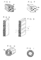
- the resulting bundle is then fused into a continuous mass as Fig. 7 shows.
- the resulting block of glass may be cut into plates by well-known methods. Such a plate is shown in Fig. 8.
- the plate may simply be fused to a flat piece of core glass of the same composition as the clear fibers in the original bundle.
- the radical pattern which is ideal for a cylindrical conduit may be approximated by sectioning a plate such as that shown in Fig. 9.
- the plate may be periodically cut into strips at an angle, alpha * , the angle chosen so that the strips may be assembled into a regular polygonal right cylindrical tube.
- the angle alpha is chosen to be 45°
- the resulting strips may be assembled into the octagonal cylindrical tube shown in Fig. 10.
- An appropriately shaped core may be inserted in this step, or preferably, the central opening 33 may be bored out into a circular cylindrical shape and a cylinder of core glass closely inserted. The entire assembly may then be fused to form an integral radiation conduit which absorbs off-axis radiation.
- An alternative embodiment of the device may be formed by the following modified steps.
- the continuous mass or block 32 shown in Fig. 7 may be cut into slabs parallel to the absorbing fibers. From these slabs, right cylindrical tubes may be cut and transparent cores inserted as above. Such a modification presents a cross-section as shown in Fig. 11.
- Another approach involves serial layering of clear and black glass to form a cylinder having planar alternate and randomly spaced layers of clear and black glass perpendicular to the axis of the cylinder.
- a central bore is formed along the axis and filled with clear glass to form the conduit.
Landscapes
- Physics & Mathematics (AREA)
- Chemical & Material Sciences (AREA)
- Engineering & Computer Science (AREA)
- Optics & Photonics (AREA)
- General Physics & Mathematics (AREA)
- Organic Chemistry (AREA)
- Materials Engineering (AREA)
- Manufacturing & Machinery (AREA)
- Life Sciences & Earth Sciences (AREA)
- Geochemistry & Mineralogy (AREA)
- General Life Sciences & Earth Sciences (AREA)
- Optical Fibers, Optical Fiber Cores, And Optical Fiber Bundles (AREA)
- Optical Couplings Of Light Guides (AREA)
- Manufacture, Treatment Of Glass Fibers (AREA)
- Light Guides In General And Applications Therefor (AREA)
- Optical Elements Other Than Lenses (AREA)
Priority Applications (1)
| Application Number | Priority Date | Filing Date | Title |
|---|---|---|---|
| AT84902735T ATE37099T1 (de) | 1983-05-24 | 1984-05-11 | Lichtfilter. |
Applications Claiming Priority (2)
| Application Number | Priority Date | Filing Date | Title |
|---|---|---|---|
| US06/497,665 US4533210A (en) | 1983-05-24 | 1983-05-24 | Optical fiber light filter using elongated radiation absorbing elements |
| US497665 | 1983-05-24 |
Publications (2)
| Publication Number | Publication Date |
|---|---|
| EP0148919A1 EP0148919A1 (en) | 1985-07-24 |
| EP0148919B1 true EP0148919B1 (en) | 1988-09-07 |
Family
ID=23977800
Family Applications (1)
| Application Number | Title | Priority Date | Filing Date |
|---|---|---|---|
| EP84902735A Expired EP0148919B1 (en) | 1983-05-24 | 1984-05-11 | Light filter |
Country Status (7)
| Country | Link |
|---|---|
| US (1) | US4533210A (https=) |
| EP (1) | EP0148919B1 (https=) |
| JP (1) | JPS60501428A (https=) |
| AU (1) | AU3150684A (https=) |
| DE (1) | DE3473935D1 (https=) |
| IL (1) | IL71651A (https=) |
| WO (1) | WO1984004821A1 (https=) |
Cited By (1)
| Publication number | Priority date | Publication date | Assignee | Title |
|---|---|---|---|---|
| DE4112587A1 (de) * | 1990-04-17 | 1991-10-24 | Asahi Optical Co Ltd | Lichtzufuehrvorrichtung |
Families Citing this family (10)
| Publication number | Priority date | Publication date | Assignee | Title |
|---|---|---|---|---|
| FR2566925B1 (fr) * | 1984-06-29 | 1987-11-27 | Blanc Michel | Dispositif concentrateur de radiations multidirectionnel non imageur |
| GB2165691A (en) * | 1984-07-26 | 1986-04-16 | Dr Jonathon Ross Howorth | Image intensifiers |
| US4669813A (en) * | 1984-08-01 | 1987-06-02 | Incom, Inc. | Faceplate incorporating an off-axis filter |
| US5319731A (en) * | 1992-10-02 | 1994-06-07 | Eastman Kodak Company | Fiber-optic array of limited acceptance angle |
| CH690657A5 (de) * | 1993-12-01 | 2000-11-30 | Olga Raimondi Staeuble | Richtblende für Beleuchtungskörper. |
| US6213607B1 (en) * | 1994-02-14 | 2001-04-10 | Nikon Corporation | Exposure apparatus and field stop thereof |
| US5926600A (en) * | 1997-05-22 | 1999-07-20 | Litton Systems, Inc. | Optical fiber for reducing optical signal reflections |
| US7856161B2 (en) * | 2007-03-21 | 2010-12-21 | Schott Corporation | Optical fiber faceplates including convergent constituent imaging conduits and tiled imaging arrays incorporating the same |
| BR102013013559A2 (pt) | 2013-05-31 | 2015-07-14 | Roberto Massaru Amemiya | Filmadora com captação tridimensional de raios e televisão produtora de imagem real formada à frente e atrás da superfície da televisão; dispositivos de filtro de raios paralelos; cristais líquidos emparelhados ou movimento de células ópticas ou filtro de raios paralelos com conjunto de lentes móveis incluindo lentes flexíveis multifocais; processos para obtenção desses dispositivos |
| JP6279880B2 (ja) * | 2013-10-31 | 2018-02-14 | 池上通信機株式会社 | 側壁反射低減構造、該構造を有する中空体および該中空体を用いた光伝送環境構築装置 |
Citations (1)
| Publication number | Priority date | Publication date | Assignee | Title |
|---|---|---|---|---|
| US532969A (en) * | 1895-01-22 | John j |
Family Cites Families (18)
| Publication number | Priority date | Publication date | Assignee | Title |
|---|---|---|---|---|
| US3247756A (en) * | 1961-05-16 | 1966-04-26 | American Optical Corp | Fiber optical image transfer device having a multiplicity of light absorbing elements |
| US4185888A (en) * | 1962-09-21 | 1980-01-29 | Quelle Fred W Jr | Cryptographic system employing optical scrambling arrays |
| US3253500A (en) * | 1964-05-11 | 1966-05-31 | American Optical Corp | Doubly clad light-conducting fibers with the outer cladding being partially light absorbing |
| US3469026A (en) * | 1966-04-22 | 1969-09-23 | Leon Winik | Tv pickup and projection system with camera having fiber optic hemispherical lens |
| US3455667A (en) * | 1966-05-06 | 1969-07-15 | American Optical Corp | Method of making optical couplers |
| GB1145630A (en) * | 1966-10-18 | 1969-03-19 | Standard Telephones Cables Ltd | Dielectric waveguide |
| US3814498A (en) * | 1972-05-04 | 1974-06-04 | Bell Telephone Labor Inc | Integrated optical circuit devices employing optical gratings |
| US3760179A (en) * | 1972-07-24 | 1973-09-18 | C Addington | Indirectly lighted panels for walls and ceilings |
| US3981706A (en) * | 1973-04-26 | 1976-09-21 | American Optical Corporation | Method for making flexible colored fiber optic device |
| JPS5015563A (https=) * | 1973-06-08 | 1975-02-19 | ||
| US3870399A (en) * | 1973-11-28 | 1975-03-11 | Corning Glass Works | Pseudo-fiber optic devices |
| US4139262A (en) * | 1974-09-06 | 1979-02-13 | Siemens Aktiengesellschaft | Filter for a light wave in a light guiding fiber |
| US4189207A (en) * | 1979-04-10 | 1980-02-19 | Fisher Charles B | Deep focus fiber optic lens |
| JPS55162700A (en) * | 1979-06-05 | 1980-12-18 | Matsushita Electric Ind Co Ltd | Optical microphone |
| FR2477288A1 (fr) * | 1980-03-03 | 1981-09-04 | Vidal Bernard | Piege a lumiere a discrimination angulaire |
| US4406973A (en) * | 1981-01-15 | 1983-09-27 | Varo, Inc. | Black glass shield and method for absorbing stray light for image intensifiers |
| JPS57190903A (en) * | 1981-05-20 | 1982-11-24 | Gensuke Kiyohara | Electromagnetic wave transmitter |
| EP0068175B1 (en) * | 1981-06-18 | 1986-04-30 | Sumitomo Electric Industries Limited | Image conducting fiber device |
-
1983
- 1983-05-24 US US06/497,665 patent/US4533210A/en not_active Expired - Fee Related
-
1984
- 1984-04-26 IL IL71651A patent/IL71651A/xx unknown
- 1984-05-11 DE DE8484902735T patent/DE3473935D1/de not_active Expired
- 1984-05-11 WO PCT/US1984/000734 patent/WO1984004821A1/en not_active Ceased
- 1984-05-11 EP EP84902735A patent/EP0148919B1/en not_active Expired
- 1984-05-11 AU AU31506/84A patent/AU3150684A/en not_active Abandoned
- 1984-05-11 JP JP59502689A patent/JPS60501428A/ja active Granted
Patent Citations (1)
| Publication number | Priority date | Publication date | Assignee | Title |
|---|---|---|---|---|
| US532969A (en) * | 1895-01-22 | John j |
Cited By (1)
| Publication number | Priority date | Publication date | Assignee | Title |
|---|---|---|---|---|
| DE4112587A1 (de) * | 1990-04-17 | 1991-10-24 | Asahi Optical Co Ltd | Lichtzufuehrvorrichtung |
Also Published As
| Publication number | Publication date |
|---|---|
| IL71651A (en) | 1987-11-30 |
| JPH0476081B2 (https=) | 1992-12-02 |
| US4533210A (en) | 1985-08-06 |
| JPS60501428A (ja) | 1985-08-29 |
| AU3150684A (en) | 1984-12-18 |
| EP0148919A1 (en) | 1985-07-24 |
| DE3473935D1 (en) | 1988-10-13 |
| WO1984004821A1 (en) | 1984-12-06 |
Similar Documents
| Publication | Publication Date | Title |
|---|---|---|
| EP0049048B1 (en) | Fluorescent activated, spatially quantitative light detector | |
| EP0148919B1 (en) | Light filter | |
| US4381137A (en) | Optical fiber mode separation systems | |
| US4676584A (en) | Fiber optic light coupling assemblies | |
| US6374024B1 (en) | Image sensor and method of manufacturing the same | |
| US6239922B1 (en) | Objective lens | |
| US5266803A (en) | Fiber optic storage phosphor imaging plate scanner | |
| GB2117512A (en) | Method of inspecting transparent rods | |
| JPS60198532A (ja) | 放射線画像情報読取装置 | |
| GB2224353A (en) | Radiation detector | |
| GB2167206A (en) | Apertured concave reflector optical system | |
| GB2115175A (en) | Fibre optics head featuring core spacing to block specular reflection | |
| US5003623A (en) | Bimodal intrusion detection in an optical fiber communication system using graded index fiber | |
| EP0144856B1 (en) | Radiation image read-out apparatus | |
| GB2112244A (en) | Improvements in or relating to monitoring apparatus | |
| EP0559118B1 (en) | Fiber optic storage phosphor imaging plate scanner | |
| CA1173491A (en) | Fluorescent activated, spatially quantitative light detector | |
| US4809611A (en) | Optical system for conical beam target detection | |
| EP0068175A1 (en) | Image conducting fiber device | |
| RU2191417C1 (ru) | Оптико-электронный прибор для дистанционного обнаружения систем скрытого видеонаблюдения | |
| EP0105461A2 (en) | Concentric core optical fiber with crosstalk barrier | |
| EP0141038B1 (en) | Image transmission path | |
| JPS5826248A (ja) | 内部全反射吸収分光光度計 | |
| EP0446348B1 (en) | Telecentric scanning for transparent storage phosphors | |
| JP2678530B2 (ja) | 太陽光校正光学系 |
Legal Events
| Date | Code | Title | Description |
|---|---|---|---|
| PUAI | Public reference made under article 153(3) epc to a published international application that has entered the european phase |
Free format text: ORIGINAL CODE: 0009012 |
|
| AK | Designated contracting states |
Designated state(s): AT BE CH DE FR GB LI LU NL SE |
|
| 17P | Request for examination filed |
Effective date: 19850603 |
|
| 17Q | First examination report despatched |
Effective date: 19860917 |
|
| GRAA | (expected) grant |
Free format text: ORIGINAL CODE: 0009210 |
|
| AK | Designated contracting states |
Kind code of ref document: B1 Designated state(s): AT BE CH DE FR GB LI LU NL SE |
|
| PG25 | Lapsed in a contracting state [announced via postgrant information from national office to epo] |
Ref country code: SE Effective date: 19880907 Ref country code: LI Effective date: 19880907 Ref country code: CH Effective date: 19880907 Ref country code: BE Effective date: 19880907 Ref country code: AT Effective date: 19880907 |
|
| REF | Corresponds to: |
Ref document number: 37099 Country of ref document: AT Date of ref document: 19880915 Kind code of ref document: T |
|
| REF | Corresponds to: |
Ref document number: 3473935 Country of ref document: DE Date of ref document: 19881013 |
|
| REG | Reference to a national code |
Ref country code: CH Ref legal event code: PL |
|
| ET | Fr: translation filed | ||
| PG25 | Lapsed in a contracting state [announced via postgrant information from national office to epo] |
Ref country code: LU Free format text: LAPSE BECAUSE OF NON-PAYMENT OF DUE FEES Effective date: 19890531 |
|
| PLBE | No opposition filed within time limit |
Free format text: ORIGINAL CODE: 0009261 |
|
| STAA | Information on the status of an ep patent application or granted ep patent |
Free format text: STATUS: NO OPPOSITION FILED WITHIN TIME LIMIT |
|
| 26N | No opposition filed | ||
| PGFP | Annual fee paid to national office [announced via postgrant information from national office to epo] |
Ref country code: GB Payment date: 19920511 Year of fee payment: 9 |
|
| PGFP | Annual fee paid to national office [announced via postgrant information from national office to epo] |
Ref country code: FR Payment date: 19920522 Year of fee payment: 9 |
|
| PGFP | Annual fee paid to national office [announced via postgrant information from national office to epo] |
Ref country code: NL Payment date: 19920531 Year of fee payment: 9 |
|
| PGFP | Annual fee paid to national office [announced via postgrant information from national office to epo] |
Ref country code: DE Payment date: 19920610 Year of fee payment: 9 |
|
| PG25 | Lapsed in a contracting state [announced via postgrant information from national office to epo] |
Ref country code: GB Effective date: 19930511 |
|
| PG25 | Lapsed in a contracting state [announced via postgrant information from national office to epo] |
Ref country code: NL Effective date: 19931201 |
|
| GBPC | Gb: european patent ceased through non-payment of renewal fee |
Effective date: 19930511 |
|
| NLV4 | Nl: lapsed or anulled due to non-payment of the annual fee | ||
| PG25 | Lapsed in a contracting state [announced via postgrant information from national office to epo] |
Ref country code: FR Effective date: 19940131 |
|
| PG25 | Lapsed in a contracting state [announced via postgrant information from national office to epo] |
Ref country code: DE Effective date: 19940201 |
|
| REG | Reference to a national code |
Ref country code: FR Ref legal event code: ST |