EP0148469A2 - Process and apparatus for separating noxious gases from a fume - Google Patents
Process and apparatus for separating noxious gases from a fume Download PDFInfo
- Publication number
- EP0148469A2 EP0148469A2 EP84115763A EP84115763A EP0148469A2 EP 0148469 A2 EP0148469 A2 EP 0148469A2 EP 84115763 A EP84115763 A EP 84115763A EP 84115763 A EP84115763 A EP 84115763A EP 0148469 A2 EP0148469 A2 EP 0148469A2
- Authority
- EP
- European Patent Office
- Prior art keywords
- flue gas
- absorption liquid
- heat exchanger
- treatment zone
- absorption
- Prior art date
- Legal status (The legal status is an assumption and is not a legal conclusion. Google has not performed a legal analysis and makes no representation as to the accuracy of the status listed.)
- Granted
Links
- 238000000034 method Methods 0.000 title claims abstract description 36
- 239000007789 gas Substances 0.000 title claims abstract description 20
- 230000008569 process Effects 0.000 title claims abstract description 8
- 239000003517 fume Substances 0.000 title 1
- 230000001473 noxious effect Effects 0.000 title 1
- 239000003546 flue gas Substances 0.000 claims abstract description 107
- UGFAIRIUMAVXCW-UHFFFAOYSA-N Carbon monoxide Chemical compound [O+]#[C-] UGFAIRIUMAVXCW-UHFFFAOYSA-N 0.000 claims abstract description 105
- 238000010521 absorption reaction Methods 0.000 claims abstract description 94
- 239000007788 liquid Substances 0.000 claims abstract description 59
- 238000004140 cleaning Methods 0.000 claims abstract description 41
- 238000001816 cooling Methods 0.000 claims abstract description 24
- 238000005406 washing Methods 0.000 claims abstract description 13
- 239000003344 environmental pollutant Substances 0.000 claims abstract description 8
- 231100000719 pollutant Toxicity 0.000 claims abstract description 8
- 239000007921 spray Substances 0.000 claims description 21
- RAHZWNYVWXNFOC-UHFFFAOYSA-N Sulphur dioxide Chemical compound O=S=O RAHZWNYVWXNFOC-UHFFFAOYSA-N 0.000 claims description 14
- 235000008733 Citrus aurantifolia Nutrition 0.000 claims description 9
- 235000011941 Tilia x europaea Nutrition 0.000 claims description 9
- 239000004571 lime Substances 0.000 claims description 9
- 239000000725 suspension Substances 0.000 claims description 9
- VTYYLEPIZMXCLO-UHFFFAOYSA-L Calcium carbonate Chemical compound [Ca+2].[O-]C([O-])=O VTYYLEPIZMXCLO-UHFFFAOYSA-L 0.000 claims description 6
- 239000008267 milk Substances 0.000 claims description 5
- 210000004080 milk Anatomy 0.000 claims description 5
- 235000013336 milk Nutrition 0.000 claims description 5
- 239000000203 mixture Substances 0.000 claims description 5
- 238000011084 recovery Methods 0.000 claims description 5
- QAOWNCQODCNURD-UHFFFAOYSA-N Sulfuric acid Chemical compound OS(O)(=O)=O QAOWNCQODCNURD-UHFFFAOYSA-N 0.000 claims description 4
- 229910000019 calcium carbonate Inorganic materials 0.000 claims description 3
- 239000000920 calcium hydroxide Substances 0.000 claims description 3
- BRPQOXSCLDDYGP-UHFFFAOYSA-N calcium oxide Chemical compound [O-2].[Ca+2] BRPQOXSCLDDYGP-UHFFFAOYSA-N 0.000 claims description 3
- 239000000292 calcium oxide Substances 0.000 claims description 3
- ODINCKMPIJJUCX-UHFFFAOYSA-N calcium oxide Inorganic materials [Ca]=O ODINCKMPIJJUCX-UHFFFAOYSA-N 0.000 claims description 3
- 239000000567 combustion gas Substances 0.000 claims description 3
- XLYOFNOQVPJJNP-UHFFFAOYSA-N water Substances O XLYOFNOQVPJJNP-UHFFFAOYSA-N 0.000 claims description 3
- 238000000746 purification Methods 0.000 claims 2
- 235000011116 calcium hydroxide Nutrition 0.000 claims 1
- 239000003570 air Substances 0.000 description 13
- 230000002378 acidificating effect Effects 0.000 description 7
- 230000000694 effects Effects 0.000 description 7
- 238000010276 construction Methods 0.000 description 6
- 239000004575 stone Substances 0.000 description 5
- OSGAYBCDTDRGGQ-UHFFFAOYSA-L calcium sulfate Chemical compound [Ca+2].[O-]S([O-])(=O)=O OSGAYBCDTDRGGQ-UHFFFAOYSA-L 0.000 description 4
- 230000008901 benefit Effects 0.000 description 3
- 230000015572 biosynthetic process Effects 0.000 description 3
- AXCZMVOFGPJBDE-UHFFFAOYSA-L calcium dihydroxide Chemical compound [OH-].[OH-].[Ca+2] AXCZMVOFGPJBDE-UHFFFAOYSA-L 0.000 description 3
- 238000006477 desulfuration reaction Methods 0.000 description 3
- 230000023556 desulfurization Effects 0.000 description 3
- 239000013505 freshwater Substances 0.000 description 3
- 238000002156 mixing Methods 0.000 description 3
- 239000000779 smoke Substances 0.000 description 3
- 229910001861 calcium hydroxide Inorganic materials 0.000 description 2
- GBAOBIBJACZTNA-UHFFFAOYSA-L calcium sulfite Chemical compound [Ca+2].[O-]S([O-])=O GBAOBIBJACZTNA-UHFFFAOYSA-L 0.000 description 2
- 235000010261 calcium sulphite Nutrition 0.000 description 2
- 230000007547 defect Effects 0.000 description 2
- 239000000446 fuel Substances 0.000 description 2
- 239000003595 mist Substances 0.000 description 2
- FAPWRFPIFSIZLT-UHFFFAOYSA-M Sodium chloride Chemical compound [Na+].[Cl-] FAPWRFPIFSIZLT-UHFFFAOYSA-M 0.000 description 1
- LSNNMFCWUKXFEE-UHFFFAOYSA-N Sulfurous acid Chemical compound OS(O)=O LSNNMFCWUKXFEE-UHFFFAOYSA-N 0.000 description 1
- 230000009471 action Effects 0.000 description 1
- 239000012080 ambient air Substances 0.000 description 1
- 238000009833 condensation Methods 0.000 description 1
- 230000005494 condensation Effects 0.000 description 1
- 230000003750 conditioning effect Effects 0.000 description 1
- 239000000356 contaminant Substances 0.000 description 1
- 238000010790 dilution Methods 0.000 description 1
- 239000012895 dilution Substances 0.000 description 1
- TXKMVPPZCYKFAC-UHFFFAOYSA-N disulfur monoxide Inorganic materials O=S=S TXKMVPPZCYKFAC-UHFFFAOYSA-N 0.000 description 1
- 238000007726 management method Methods 0.000 description 1
- 230000035515 penetration Effects 0.000 description 1
- 239000002244 precipitate Substances 0.000 description 1
- 230000009467 reduction Effects 0.000 description 1
- 238000000926 separation method Methods 0.000 description 1
- 239000002002 slurry Substances 0.000 description 1
- 239000011780 sodium chloride Substances 0.000 description 1
- 235000002639 sodium chloride Nutrition 0.000 description 1
- 239000007787 solid Substances 0.000 description 1
- 239000000243 solution Substances 0.000 description 1
- 239000000126 substance Substances 0.000 description 1
- XTQHKBHJIVJGKJ-UHFFFAOYSA-N sulfur monoxide Chemical compound S=O XTQHKBHJIVJGKJ-UHFFFAOYSA-N 0.000 description 1
- 230000002123 temporal effect Effects 0.000 description 1
- 238000011144 upstream manufacturing Methods 0.000 description 1
Images


Classifications
-
- B—PERFORMING OPERATIONS; TRANSPORTING
- B01—PHYSICAL OR CHEMICAL PROCESSES OR APPARATUS IN GENERAL
- B01D—SEPARATION
- B01D53/00—Separation of gases or vapours; Recovering vapours of volatile solvents from gases; Chemical or biological purification of waste gases, e.g. engine exhaust gases, smoke, fumes, flue gases, aerosols
- B01D53/34—Chemical or biological purification of waste gases
- B01D53/46—Removing components of defined structure
- B01D53/48—Sulfur compounds
- B01D53/50—Sulfur oxides
- B01D53/501—Sulfur oxides by treating the gases with a solution or a suspension of an alkali or earth-alkali or ammonium compound
Abstract
Bei dem Verfahren und der Vorrichtung zum Abscheiden von Schadstoffen aus einem Rauchgas wird in einer Absorptions-Wärmetauscheranordnung (1) sowohl das Waschen als auch das Kühlen des Rauchgases vorgenommen, wobei das Rauchgas unter den Taupunkt gekühlt wird und dieser Kühlvorgang durch Außenluft im Gegenstrom erfolgt. Das Rauchgas wird bei seinem Durchtritt durch den Wärmetauscher in mindestens zwei parallel geführte Teilströme aufgeteilt, von denen der erste Teilstrom in eine erste Behandlungszone (12) und der zweite Teilstrom in eine zweite Behandlungszone (11) eingeleitet wird. Die beiden Behandlungszonen sind parallel zueinander geschaltet. In der ersten Behandlungszone (12) wird in das Rauchgas eine erste Absorptionsflüssigkeit eingebracht, die ein weitgehendes Ausfällen der Schadstoffe aus dem Rauchgas bewirkt (Gasreinigung), während in der zweiten Behandlungszone (11) in das Rauchgas eine zweite Absorptionsflüssigkeit eingebracht wird, in der die ausgefällten Schadstoffe löslich sind (Anlagenreinigung). Diese beiden Behandlungszonen werden zyklisch getauscht.In the method and the device for separating pollutants from a flue gas, both the washing and the cooling of the flue gas are carried out in an absorption heat exchanger arrangement (1), the flue gas being cooled below the dew point and this cooling process being carried out by countercurrent outside air. As it passes through the heat exchanger, the flue gas is divided into at least two partial flows which are conducted in parallel, of which the first partial flow is introduced into a first treatment zone (12) and the second partial flow into a second treatment zone (11). The two treatment zones are connected in parallel to each other. In the first treatment zone (12), a first absorption liquid is introduced into the flue gas, which largely causes the pollutants to precipitate out of the flue gas (gas cleaning), while in the second treatment zone (11) a second absorption liquid is introduced into the flue gas, in which the precipitated pollutants are soluble (system cleaning). These two treatment zones are exchanged cyclically.
Description
Die Erfindung bezieht sich auf ein Verfahren zum Abscheiden von Schadstoffen aus einem Rauchgas gemäß den Merkmalen des Oberbegriffs der Ansprüche 1 und 7 sowie auf eine Vorrichtung zur Durchführung des Verfahrens entsprechend den Merkmalen des Oberbegriffs des Anspruchs 8.The invention relates to a method for separating pollutants from a flue gas according to the features of the preamble of
Derartige Verfahren und Vorrichtungen sind in verschiedenen Ausführungsformen seit langem bekannt. Dabei wird in der Regel zur Reinigung schwefeldioxidhaltiger Abgase als Absorptionsflüssigkeit eine Calciumkarbonatsuspension, Kalkmilch, eine Calciumoxidsuspension oder ein Gemisch hiervon eingesetzt. Da jedoch das beim Auswaschen mit einer derartigen Absorptionsflüssigkeit aus dem Rauchgas ausgefällte Calciumsulfit bzw. Calciumsulfat eine niedrige Löslichkeit besitzt, kommt es in relativ kurzer Zeit in den Absorptionseinrichtungen zu einer Ablagerung dieser Ausfällungen in Form eines Steinansatzes. Dieser hat einen zunehmenden Druckverlust in den Absorptionseinrichtungen und eine Abnahme des Wirkungsgrades dieser Einrichtungen zur Folge.Such methods and devices have long been known in various embodiments. As a rule, a calcium carbonate suspension, lime milk, a calcium oxide suspension or a mixture thereof is used as the absorption liquid for cleaning exhaust gases containing sulfur dioxide. However, since washing out with of such an absorption liquid from the flue gas precipitated calcium sulfite or calcium sulfate has a low solubility, these precipitates are deposited in the absorption devices in the form of a stone batch in a relatively short time. This results in an increasing pressure loss in the absorption devices and a decrease in the efficiency of these devices.
Es wurde versucht, diesen Steinansatz entweder auf mechanischem oder chemischem Weg wieder aus den Einrichtungen zu entfernen. Die Erfindung bezieht sich nun auf die Weiterbildung einer chemischen Verfahrensweise.An attempt was made to remove this stone deposit from the facilities either mechanically or chemically. The invention now relates to the development of a chemical procedure.
Bei einem Verfahren und einer Vorrichtung der vorausgesetzten Art (DE-AS 2 161 475) strömt der Rauchgasstrom durch einen Kühlturm und nachfolgend durch zwei Absorptionstürme. In der ersten Absorptionseinheit ist der pH-Wert kleiner als 4 zur Entfernung des Steinansatzes gehalten, während in der zur ersten in Reihe geschalteten zweiten Einheit zur Erzielung einer möglichst großen Gasreinigungswirkung ein pH-Wert größer als 7 eingestellt ist. Durch zyklisches Umschalten des Rauchgasstromes und der Steuerung der pH-Werte in den beiden Absorptionstürmen, also einen gegenläufigen Betrieb der in Reihe geschalteten Einrichtungen, wird eine Reinigung der Anlage bei konstantem Entschwefelungsgrad ohne Betriebsunterbrechung erreicht. Bei diesem bekannten Verfahren wirkt sich aber als nachteilig aus, daß drei Türme mit hohen Investitionskosten vorgesehen werden müssen und daß die Überwindung des rauchgasseitigen Druckverlustes der Anlage mit großem Energieaufwand verbunden ist. Der Betrieb des Kühlturmes, in welchem gleichzeitig die festen Bestandteile aus dem Rauchgas durch verdüstes Wasser entfernt werden, verursacht zudem einen hohen Frischwasserverbrauch und verhindert eine Nutzung der Restenergie im Rauchgas. Auch zum Betreiben der Absorptionstürme muß zur Herstellung der Kalkaufschlämmung Frischwasser vewendet werden. Zudem muß im Falle eines schon in einem der beiden Absorptionstürme auftretenden Defekts die gesamte Reinigungsanlage stillgesetzt werden.In a method and an apparatus of the type described (DE-AS 2 161 475), the flue gas stream flows through a cooling tower and subsequently through two absorption towers. In the first absorption unit, the pH value is kept below 4 to remove the stone deposit, while in the second unit connected in series with the first unit, a pH value above 7 is set to achieve the greatest possible gas cleaning effect. By cyclically switching the flue gas flow and controlling the pH values in the two absorption towers, i.e. operating the devices connected in series in opposite directions, the system can be cleaned at a constant level of desulfurization without interrupting operation. This known method has the disadvantage that three towers with high investment costs must be provided and that the overcoming of the smoke-side pressure loss the system is associated with a large amount of energy. The operation of the cooling tower, in which the solid components are simultaneously removed from the flue gas by means of atomized water, also causes high fresh water consumption and prevents the residual energy in the flue gas from being used. Fresh water must also be used to operate the lime slurry to operate the absorption towers. In addition, in the event of a defect already occurring in one of the two absorption towers, the entire cleaning system must be shut down.
Aufgabe der Erfindung ist es, ein Verfahren und Vorrichtungen zur Abscheidung von Schadstoffen aus einem Rauchgas zu schaffen, bei denen bei einfacher, wirtschaftlicher Verfahrensführung und damit einfachem, wirtschaftlichem und komptaktem Aufbau der Vorrichtung ein großer Reinigungseffekt erzielt wird. Zudem soll eine hohe Betriebssicherheit erreicht werden.The object of the invention is to provide a method and devices for separating pollutants from a flue gas, in which a large cleaning effect is achieved with simple, economical process management and thus simple, economical and compact structure of the device. In addition, high operational reliability is to be achieved.
Diese Aufgabe wird erfindungsgemäß durch Verfahren und eine Vorrichtung mit den Merkmalen der Ansprüche 1 bzw. 7 sowie des Anspruches 8 gelöst. Während das Verfahren nach Anspruch 1 in einer einzigen Anordnung, in der gleichzeitig sowohl das Kühlen als auch das Waschen des Rauchgases vorgenommen werden, durchgeführt wird, arbeitet das Verfahren nach Anspruch 7 mit an sich bekannten Absorptionstürmen.This object is achieved according to the invention by a method and a device with the features of
Ein erster grundlegender Unterschied zwischen der bekannten Betriebsweise und dem erfindungsgemäßen Verfahren besteht darin, daß bei der bekannten Lösung die Absorptionseinrichtungen in Reihe geschaltet sind und ein zyklisches Umkehren der Betriebsweise erfolgt.A first fundamental difference between the known mode of operation and the method according to the invention is that in the known solution the absorption devices are connected in series and the mode of operation is cyclically reversed.
Das erfindungsgemäße Konzept ist hingegen durch ein Parallelschalten der unterschiedlichen Behandlungszonen und einen Parallelbetrieb dieser beiden Behandlungszonen gekennzeichnet. Das erfindungsgemäße Konzept beruht danach auf einem andersartigen Prinzip.In contrast, the concept according to the invention is characterized by a parallel connection of the different treatment zones and a parallel operation of these two treatment zones. The concept according to the invention is based on a different principle.
Ein weiterer gravierender Unterschied zwischen dem Stand der Technik und der Erfindung ist darin zu sehen, daß erfindungsgemäß in einer einzigen Anordnung gleichzeitig sowohl das Kühlen als auch das Waschen des Rauchgases vorgenommen werden. Konkret wird also ein Absorptions-Wärmetauscher eingesetzt. Hierdurch ergibt sich eine besonders kompakte Vorrichtung.Another serious difference between the prior art and the invention can be seen in the fact that, according to the invention, both the cooling and the washing of the flue gas are carried out simultaneously in a single arrangement. In concrete terms, an absorption heat exchanger is used. This results in a particularly compact device.
Zwar sind Absorptions-Wärmetauscher, die bei dem Verfahren nach Anspruch 1 zugrundegelegt werden, an sich bekannt (DE-AS 2 263 319). Bei diesen bekannten Absorptions-Wärmetauschern ist aber das Problem des chemischen Abreinigens von Steinsalz beim Waschen schwefeldioxidhaltiger Verbrennungsgase mit einschlägigen Absorptionsflüssigkeiten weder angesprochen noch gelöst.Absorption heat exchangers on which the method according to claim 1 is based are known per se (DE-AS 2 263 319). In these known absorption heat exchangers, however, the problem of chemically cleaning rock salt when washing combustion gases containing sulfur dioxide with relevant absorption liquids is neither addressed nor solved.
Des weiteren wird bei dem erfindungsgemäßen Verfahren das Rauchgas in dem Absorptions-Wärmetauscher unter Taupunkt gekühlt. Das dabei aus dem Rauchgas ausgeschiedene Kondensat erhöht den Reinigungseffekt des erfindungsgemäßen Verfahrens, da das Kondensat die Menge an Absorptionsflüssigkeit insgesamt erhöht. Dabei werden Absorptionsflüssigkeit und Rauchgas über einen relativ langen Strömungsweg und damit innerhalb einer hohen Verweilzeit und zudem über große Austauschflächen miteinander in Berührung gebracht.Furthermore, in the process according to the invention, the flue gas is cooled below the dew point in the absorption heat exchanger. The condensate separated out from the flue gas increases the cleaning effect of the method according to the invention, since the condensate increases the amount of absorption liquid overall. Absorption liquid and flue gas are brought into contact with each other over a relatively long flow path and thus within a long dwell time and also over large exchange areas.
Ein weiterer wesentlicher Vorteil des erfindungsgemäßen Konzepts ist darin zu sehen, daß aufgrund des Parallelstrom-Prinzips bei Ausfall einer von mehreren Behandlungszonen die übrigen Behandlungszonen weiter betrieben werden können, während bei der bekannten Konstruktion ein derartiger Schadensfall zu einem Abschalten der gesamten Anlage zwingt.Another significant advantage of the concept according to the invention is that, due to the parallel flow principle, if one of several treatment zones fails, the other treatment zones can continue to be operated, while in the known construction such a case of damage forces the entire system to be switched off.
Bei dem Verfahren nach Anspruch 7 wird ebenfalls mit an sich bekannten Absorptionstürmen (vgl. z.B. DE-AS 2 161 475) gearbeitet. Auch hier wird das Rauchgas in zwei Teilströme aufgeteilt und parallel den beiden Behandlungszonen zugeführt. Bei einer Gesamtzahl von z.B. sechs Absorptionstürmen werden vorzugsweise fünf Absorptionstürme jeweils im Sinne einer Gasreinigung gefahren, während der verbleibende eine Absorptionsturm in Sinne einer Anlagenreinigung gefahren wird. Die Steuerung der pH-Werte sowie das zyklische Umschalten der einzelnen Behandlungszonen, die durch jeweils einen Turm gebildet werden, erfolgt in der beschriebenen Weise.In the method according to
Bei dem erfindungsgemäßen Verfahren bietet es sich an, durch die erste Behandlungszone (Gasreinigung) einen größeren Teilstrom des Rauchgases hindurchzuleiten als durch die zweite Behandlungszone, in der die Anlagenreinigung stattfindet. Danach wird also überwiegend das Gas der gewünschten Reinigung unterzogen und nur ein Teil des möglichen Gasreinigungsbetriebes aufgegeben und hierfür die Reinigung eines kleineren Teils der Anlage vorgenommen. Im Verlauf des Betriebs wird dann zyklisch ein Teil der ersten Behandlungszone durch Betreiben mit der zweiten Absorptionsflüssigkeit im Sinne einer Anlagenreinigung betrieben, während die Behandlungszone, in der die Anlagenreinigung vorgenommen worden ist, wieder im Sinne einer Gasreinigung eingesetzt wird.In the method according to the invention, it is advisable to pass a larger partial flow of the flue gas through the first treatment zone (gas cleaning) than through the second treatment zone in which the plant cleaning takes place. After this, the gas is predominantly subjected to the desired cleaning and only part of the possible gas cleaning operation is abandoned and a smaller part of the system is cleaned for this purpose. During the course of operation, part of the first treatment zone is then cyclically operated with the second absorption liquid operated in the sense of a plant cleaning, while the treatment zone in which the plant was cleaned is used again in the sense of a gas cleaning.
Beim Reinigen von schwefeldioxidhaltigen Rauchgasen ist es zweckmäßig, daß die erste Absorptionsflüssigkeit Kalkmilch, Calciumoxidsuspension, Calciumcarbonatsuspension oder eine Mischung hiervon ist, während die zweite Absorptionsflüssigkeit Wasser und darin gelöste schwefelige Säure aus dem Rauchgas ist, d.h. unbehandeltes Kondensat.When cleaning flue gases containing sulfur dioxide, it is expedient that the first absorption liquid is lime milk, calcium oxide suspension, calcium carbonate suspension or a mixture thereof, while the second absorption liquid is water and sulfuric acid dissolved therein from the flue gas, i.e. untreated condensate.
Die Reinigung der Anlage erfolgt also mit unbehandeltem Kondensat, das sich durch mehrmaliges Hindurchleiten durch die zweite Behandlungszone sauer einstellt und damit den Steinansatz aus Calciumsulfit bzw. Calciumsulfat löst, der während der Gasreinigungsphase gebildet wird.The system is therefore cleaned with untreated condensate, which is acidified by repeated passage through the second treatment zone and thus dissolves the stone batch from calcium sulfite or calcium sulfate, which is formed during the gas cleaning phase.
Es ist ferner von Vorteil, daß eine Vorkühlung des Rauchgases bis auf 40°C bis 60°C mit Hilfe einer Wärmerückgewinnung vorgenommen wird. Hier wird ein wesentlicher Teil der Wärme aus dem Rauchgas zurückgewonnen. Damit läßt sich eine nach dem erfindungsgemäßen Verfahren betriebene Anlage mit einem guten energetischen Wirkungsgrad fahren.It is also advantageous that the flue gas is pre-cooled to 40 ° C to 60 ° C with the aid of heat recovery. Here a significant part of the heat is recovered from the flue gas. This allows a system operated according to the method of the invention to be operated with good energy efficiency.
Durch diese Maßnahme werden noch weitere zwei Vorteile erreicht. Zum einen kann die rückgewonnene Wärme nutzbringend für weitere Prozesse eingesetzt werden. Zum anderen erreicht das Rauchgas mit der richtigen Konditionierung die Reinigungsanordnung, da es dann schon im wesentlichen auf Taupunkttemperatur abgekühlt ist mit der Folge, daß im Wärmetauscher sofort die Kondensatbildung einsetzt und die angestrebte Menge an Kondensat tatsächlich im Absorptions-Wärmetauscher ausgeschieden wird. Neben der Eintrittstemperatur des Rauchgases in die Anordnung, die, wie geschildert worden ist, günstig erreicht wird durch das Vorschalten einer Wärmerückgewinnungsanlage, sind natürlich wesentlich die zeitlichen Mengen an Außenluft und Rauchgas, die den Wärmetauscher durchströmen. Hinzu kommt die richtige Bemessung der Wärmetausch-Flächen. Die angesprochenen richtigen zeitlichen Mengen der Umgebungsluft und des Rauchgases sind selbstverständlich auch wesentlich für die nach der Reinigung sich anschließende Mischung beider Strömungen zur Vermeidung von Schwaden- und Nebelbildung.This measure achieves two further advantages. On the one hand, the recovered heat can be used for other processes. On the other hand, the flue gas reaches the cleaning arrangement with the correct conditioning, since it then is essentially cooled to the dew point temperature with the result that condensate formation starts immediately in the heat exchanger and the desired amount of condensate is actually excreted in the absorption heat exchanger. In addition to the inlet temperature of the flue gas into the arrangement, which, as has been described, can be achieved favorably by connecting a heat recovery system upstream, the time quantities of outside air and flue gas flowing through the heat exchanger are of course essential. In addition there is the correct dimensioning of the heat exchange surfaces. The correct temporal amounts of the ambient air and the flue gas mentioned are of course also essential for the subsequent mixing of the two flows to avoid the formation of steam and mist.
Diese weitere zweckmäßige Verfahrensvariante besteht darin, daß das gereinigte Rauchgas mit der für die Kühlung des Rauchgases eingesetzten Außenluft vor Eintritt in die Atmosphäre vermischt wird. Durch diese Maßnahme wird zum einen der Taupunkt des Gasgemisches erhöht, wodurch einer Nebel- bzw. Schwadenbildung entgegengewirkt wird. Zum anderen können aufgrund des zugleich erreichten Verdünnungseffekts die gegebenfalls im Rauchgas verbliebenen geringen Mengen an Schadstoffen in zulässiger Weise in die Atmosphäre entlassen werden.This further expedient method variant consists in that the cleaned flue gas is mixed with the outside air used for cooling the flue gas before it enters the atmosphere. On the one hand, this measure increases the dew point of the gas mixture, which counteracts the formation of mist or vapor. On the other hand, due to the dilution effect achieved at the same time, the small amounts of pollutants that may remain in the flue gas can be released into the atmosphere in a permissible manner.
Eine weitere zweckmäßige Ausbildung des erfindungsgemäßen Verfahrens besteht darin, daß das Rauchgas aus der zweiten Behandlungszone (Anlagenreinigung) in den Waschzyklus zurückgeführt wird. Durch diese Verfahrensvariante wird eine besonders weitgehende Reinigung des Rauchgases erreicht, indem das in der Behandlungszone, die der Anlagenreinigung dient, nicht so gut von Schadstoffen befreite Rauchgas einem weiteren Reinigungszyklus unterworfen wird.Another useful embodiment of the method according to the invention is that the flue gas from the second treatment zone (plant cleaning) in the Washing cycle is recycled. This variant of the method achieves a particularly extensive cleaning of the flue gas by subjecting the flue gas, which is not so well freed of contaminants in the treatment zone that serves to clean the plant, to a further cleaning cycle.
Schließlich besteht eine Weiterbildung des erfindungsgemäßen Verfahrens darin, daß 5/6 des zu reinigenden Rauchgasstromes mit der ersten Absorptionsflüssigkeit und 1/6 mit der zweiten Absorptionsflüssigkeit durchsetzt werden und daß der Umschaltzyklus ein bis vier Stunden dauert. Hierdurch ergibt sich ein besonders guter Wirkungsgrad des erfindungsgemäßen Verfahrens.Finally, a further development of the method according to the invention is that 5/6 of the flue gas stream to be cleaned is permeated with the first absorption liquid and 1/6 with the second absorption liquid and that the switching cycle lasts from one to four hours. This results in a particularly good efficiency of the method according to the invention.
Je nach Art des verwendeten Brennstoffs, aus dem das zu behandelnde Rauchgas herrührt, kann sich ein pH-Wert bis 1,0 einstellen, während nach dem Austritt aus den Behandlungszonen, die der Gasreinigung dienen, die Absorptionsflüssigkeit einen pH-Wert von mindestens 5 aufweisen soll. Durch diese Werte wird einerseits eine besonders gute Reinigung der Anlage durch das relativ saure Kondensat, das die sogenannte zweite Absorptionsflüssigkeit darstellt, sowie eine gute Schwefeldioxidabsorption in den der Gasreinigung dienenden Behandlungszonen durch einen hohen pH-Wert erzielt.Depending on the type of fuel used, from which the flue gas to be treated originates, a pH value of up to 1.0 can be set, while after exiting the treatment zones used for gas cleaning, the absorption liquid has a pH value of at least 5 should. On the one hand, these values result in particularly good cleaning of the system by means of the relatively acidic condensate, which is the so-called second absorption liquid, and good sulfur dioxide absorption in the treatment zones used for gas cleaning due to a high pH value.
Die erfindungsgemäße Vorrichtung ist grundsätzlich dadurch charakterisiert, daß eine Absorptions-Wärmetauscheranordnung zum gleichzeitigen Kühlen des Rauchgases unter Taupunkt als auch zum Waschen des Rauchgases vorgesehen ist und in dieser Absorptions-Wärmetauscheranordnung die mindestens zwei Betriebszonen parallel zueinander geschaltet sind. Das Rauchgas wird, wie bereits geschildert, in zwei parallel geführte Teilströme aufgeteilt, von denen der eine Teilstrom durch die erste Behandlungszone und der andere durch die zweite Behandlungszone geleitet wird.The device according to the invention is basically characterized in that an absorption heat exchanger arrangement for simultaneous cooling of the flue gas below the dew point and also for washing the smoke gases is provided and in this absorption heat exchanger arrangement the at least two operating zones are connected in parallel. As already described, the flue gas is divided into two parallel partial flows, one of which is passed through the first treatment zone and the other through the second treatment zone.
Die erfindungsgemäße Einrichtung zeichnet sich durch eine kompakte Bauweise aus, nachdem die Funktionen des Kühlens und Waschens des Rauchgases in ein Gerät integriert sind, nämlich in einen Absorptions-Wärmetauscher. Bezüglich des Wärmetauscherteils sind die beiden unterschiedlichen Betriebszonen, nämlich die eine für die Gasreinigung und die andere für die Anlagenreinigung, identisch ausgebildet, so daß auch ein einfacher Aufbau der Konstruktion gewährleistet ist.The device according to the invention is characterized by a compact design, after the functions of cooling and washing the flue gas are integrated in one device, namely in an absorption heat exchanger. With regard to the heat exchanger part, the two different operating zones, namely one for gas cleaning and the other for system cleaning, are designed identically, so that a simple construction of the construction is ensured.
Es ist zweckmäßig, daß der Wärmetauscher aus einer Mehrzahl von parallel angeordneten Rohren besteht, wobei das Rauchgas in den Rohren und die Kühlluft in den Raum zwischen den Rohren geführt sind sowie daß Rohre des Wärmetauschers vertikal verlaufen und das Rauchgas die Rohre von oben nach unten durchströmt, während die Kühlluft im Gegenstrom von unten nach oben geführt wird.It is expedient that the heat exchanger consists of a plurality of tubes arranged in parallel, the flue gas in the tubes and the cooling air being guided into the space between the tubes, and that tubes of the heat exchanger run vertically and the flue gas flows through the tubes from top to bottom , while the cooling air is directed in counterflow from bottom to top.
Hierdurch werden zwei Vorteile erreicht. Zum einen ergibt sich für den Absorptions-Wärmetauscher eine schornsteinähnliche Form. Dies begünstigt das Vorsehen eines langen Rauchgaskamins, in dem eine gute Mischung des in die Atmosphäre zu entlassenden Rauchgases und der als Kühlluft eingesetzten Außenluft stattfindet, mit dem schon erörterten Zweck. Das Gegenstromprinzip bezüglich der Führung des Rauchgases und der Kühlluft führt des weiteren zu einem guten Herabkühlen des Rauchgases unter Taupunkt und zu einer optimalen Ausnutzung der Tauscherflächen.This achieves two advantages. On the one hand, there is a chimney-like shape for the absorption heat exchanger. This favors the provision of a long flue gas fireplace, in which a good mixture of the flue gas to be released into the atmosphere and the outside air used as cooling air takes place with the purpose already discussed. The countercurrent principle with regard to the guidance of the flue gas and the cooling air also leads to a good cooling of the flue gas below the dew point and to an optimal use of the exchanger surfaces.
Eine zweckmäßige Ausgestaltung der erfindungsgemäßen Vorrichtung besteht darin, daß die Sprühdüsen für die Absorptionsflüssigkeit oberhalb des Eintritts für das Rauchgas in den Wärmetauscher angeordnet sind, so daß ein Gleichstrom-Waschen stattfindet. Aufgrund dieser Maßnahme strömen das Kondensat aus dem Rauchgas, das bei dessen Abkühlung unter Taupunkt entsteht, und die zusätzliche Absorptionsflüssigkeit in einer Richtung mit der Folge eines besonders guten Wascheffekts, der zusätzlich auch durch die Nutzung möglichst großer Tauscherflächen und des Einhaltens einer besonders langen Wirkzeit erhöht wird.An expedient embodiment of the device according to the invention is that the spray nozzles for the absorption liquid are arranged above the entry for the flue gas into the heat exchanger, so that a direct current washing takes place. As a result of this measure, the condensate flows from the flue gas, which is produced when it cools below the dew point, and the additional absorption liquid flows in one direction, resulting in a particularly good washing effect, which also increases through the use of the largest possible exchanger surfaces and by maintaining a particularly long working time becomes.
Ein besonders einfacher Aufbau der erfindungsgemäßen Vorrichtung ergibt sich dadurch, daß die Rohre des Wärmetauschers in einem Kreisring angeordnet und die Rohre innerhalb von mehreren Sektoren jeweils zu einer Betriebszone zusammengefaßt sind. Dadurch weisen nämlich die Betriebszonen des Wärmetauscher einen identischen Aufbau auf. Die einzelnen Betriebszonen entstehen nur dadurch, daß entweder mit der ersten oder zweiten Absorptionsflüssigkeit in den einzelnen Zonen gearbeitet wird.A particularly simple construction of the device according to the invention results from the fact that the tubes of the heat exchanger are arranged in a circular ring and the tubes are combined to form an operating zone within several sectors. As a result, the operating zones of the heat exchanger have an identical structure. The individual operating zones arise only by working with either the first or second absorption liquid in the individual zones.
Für die Versorgung der Betriebszonen jeweils mit der ersten oder zweiten Absorptionsflüssigkeit bestehen grundsätzlich zwei Möglichkeiten.There are basically two options for supplying the operating zones with the first or second absorption liquid.
Die erste Variante ist dadurch charakterisiert, daß jeder Betriebszone ein eigenes Versorgungssystem für die Absorptionsflüssigkeit zugeordnet ist, das von der ersten auf die zweite Absorptionsflüssigkeit und umgekehrt umschaltbar ist.The first variant is characterized in that each operating zone is assigned its own supply system for the absorption liquid, which can be switched over from the first to the second absorption liquid and vice versa.
Die zweite prinzipielle Möglichkeit ist darin zu sehen, daß sämtliche Behandlungszonen eine Sprühdüsenanordnung für die erste Absorptionsflüssigkeit aufweisen und eine weitereThe second basic possibility is to be seen in the fact that all treatment zones have a spray nozzle arrangement for the first absorption liquid and a further one
Sprühdüsenanordnung für die zweite Absorptionsflüssigkeit vorgesehen ist, die wahlweise über den Eintritt der jeweiligen Behandlungszone, die mit der zweiten Absorptionsflüssigkeit betrieben wird, einstellbar ist.Spray nozzle arrangement is provided for the second absorption liquid, which is optionally adjustable via the entry of the respective treatment zone, which is operated with the second absorption liquid.
Die Erfindung wird nachstehend anhand der in den beigefügten Zeichnungen dargestellten Ausführungsbeispielen näher erläutert.The invention is explained below with reference to the embodiments shown in the accompanying drawings.
Es zeigt:
- Fig. 1 in schematischer Darstellung einen vertikalen Schnitt durch eine erste Ausführungsform der erfindungsgemäßen Vorrichtung,
- Fig. 2 einen Querschnitt durch diese Ausführungsform nach der Schnittlinie II-II der Fig. 1,
- Fig. 3 in schematischer Darstellungsweise einen Längsschnitt durch eine zweite Ausführungsform der erfindungsgemäßen Vorrichtung und
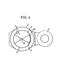
- Fig. 4 eine Draufsicht auf die Vorrichtung nach Fig. 3.
- 1 is a schematic representation of a vertical section through a first embodiment of the device according to the invention,
- 2 shows a cross section through this embodiment along the section line II-II of FIG. 1,
- Fig. 3 shows a schematic representation of a longitudinal section through a second embodiment of the device according to the invention and
- 4 shows a top view of the device according to FIG. 3.
In den Fig. l und 2, die eine erste Ausführungsform darstellen, ist ein Absorptions-Wärmetasucher insgesamt mit 1 bezeichnet. Dieser ist im wesentlichen schornstein- bzw. turmförmig aufgebaut. Er weist ein im wesentlichen zylindrisches, vertikal stehendes Gehäuse 2 auf, in welchem zentrisch ein rohrförmiger Rauchgaskamin 3 im wesentlichen durch das ganze Gehäuse hindurchgehend angeordnet ist. Am oberen Ende des Gehäuses 1 ist ein ringförmiger Verteilungskanal 4 vorgesehen, in welchen eine Eintrittsleitung 5 für das zu reinigende Rauchgas einmündet. Die überwiegende Höhe des Gehäuses 2 wird von einem Wärmetauscher 6 eingenommen, welcher aus vertikal verlaufenden Rohren 7 für den Durchtritt des Rauchgases besteht. An den Stirnenden der Rohre 7 sind die Zwischenräume zwischen den Rohren 7 jeweils verschlossen, so daß ein oberer Eintritt 8 und ein unterer Austritt 9 für das Rauchgas gebildet wird. Der Eintritt 8 und der Austritt 9 des Wärmetauschers 6 ist vorzugsweise in sechs nebeneinander angeordnete, sektorenartige, sich um den Rauchgaskamin 3 gruppierende Zonen mit Hilfe von radialen Wänden 13 unterteilt. Fünf der Zonen, hier mit 12 bezeichnet, bilden in noch näher zu beschreibender Weise jeweils eine erste Betriebszone, während eine der Zonen, hier mit 11 gekennzeichnet, eine zweite Betriebszone darstellt. Allen Zonen 11 bzw. 12 gemeinsam ist an der Unterseite des Gehäuses 2 ein Kühlluft-Gebläse 10 zugeordnet, welches angesaugte Frischluft am unteren Ende des Wärmetauschers 6 zwischen die Rohre 7 einleiten, so daß die Kühlluft eine Flußrichtung von unten nach oben, also entgegengesetzt der Rauchgasströmung, besitzt. Am unteren Teil des Gehäuses 2, unterhalb des unteren Austritts 9 des Wärmetauschers 6, ist eine ebenfalls zonenmäßig unterteilte Sammelwanne 14 vorgesehen, die zur Aufnahme bzw. Weiterleitung des austretenden Rauchgases und des Kondensates dient. Der Boden der Sammelwanne 14 ist in jeder Zone über eine Kondensatleitung 15 mit je einem Behälter 16 verbunden. In den jeweiligen Behälter 16 mündet eine mit einem Kalkmilch-Behälter 18 verbundene Leitung 17 ein. In der Leitung 17 ist eine Dosiereinrichtung 19 vorgesehen. Aus einem jeden der Behälter 16 führt eine ein pH-Messgerät 21 aufweisende Leitung 20 in das Innere des Verteilungskanales 4, wo sie in Sprühdüsen 22 enden, die jeweils über dem Eintritt 8 der zugeordneten Zone 11 bzw. 12 angeordnet sind.1 and 2, which represent a first embodiment, an absorption heat exchanger is designated by 1 as a whole. This is essentially chimney or tower-shaped. It has an essentially cylindrical, vertically standing
In der zylindrischen Innenwand der Sammelwanne 14 sind in jeder Zone 11 bzw. 12 zwei durch Klappen wechselweise verschließbare Öffnungen 23 bzw. 24 vorgesehen. Die obere Öffnung 23 steht jeweils mit dem Rauchgaskamin 3 in Verbindung. Die untere Öffnung 24 führt in eine vom Rauchgaskamin abgetrennte Kammer 25, welche über eine Bypassleitung 26, in der ein Zusatzgebläse 27 angeordnet ist, mit der Eintrittsleitung 5 verbunden ist.In the cylindrical inner wall of the collecting trough 14, two
Der Wärmetauscher 6 weist am oberen Ende an seiner dem Rauchgaskamin 3 zugewandten Wand Öffnungen 29 auf, die eine Verbindung zum Rauchgaskamin darstellen. Auf Höhe der Öffnungen 29 ist im Rauchgaskamin 3 ein perforiertes Durchtrittsdach 30 vorgesehen, welches der besseren Vermischung des Rauchgases mit der erwärmten Kühlluft dient.At its upper end, the
Dem Absorptions-Wärmetauscher 1 ist eine nur schematisch dargestellte, in bekannter Weise arbeitende Wärmerückgewinnungsanlage 31 vorgeschaltet.The absorption heat exchanger 1 is preceded by a
Die Vorrichtung nach den Fig. 1 und 2 arbeitet folgendermaßen:
- Das in
der Wärmerückgewinnungsanlage 31 bis auf vorzugsweise 40°C bis 60°C vorgekühlte Rauchgas tritt über die Eintrittsleitung 5 in die ringförmige Verteilungskammer 4 ein, in der sie in Teilströmen gleichmäßig auf die sechs Zonen 11 bzw. 12 verteilt wird.Am Eintritt 8 jeder Zone 11 bzw. 12 wird eine Absorptionsflüssigkeit über dieSprühdüsen 22 auf die Tauschflächen des Absorptions-Wärmetauschers aufgesprüht. Dabei wird in die fünfZonen 12 als sogenannte erste Absorptionsflüssigkeit ein mittels Calciumhydroxid oder einer ähnlichen Kalksuspension neutralisiertes Kondensat eingebracht, während in der sechsten Zone 11 als sogenannte zweite Absorptionsflüssigkeit unbehandeltes Kondensat eingedüst wird. Es hat sich gezeigt, daß dieses unbehandelte Kondensat, das schwefelige Säure aufgrund aus dem Rauchgas ausgewaschenen Schwefeldioxids enthält, eine ausgezeichnete Reinigungswirkung auf Ablagerungen aufweist, welche überlicherweise in Rauchgasreinigungsanlagen auftreten. Allerdings ist in dieser Zone z.B. der Entschwefelungswirkungsgrad relativ niedrig, so daß das nur teilweise entschwefelte Rauchgasam Zonenaustritt 9 des Absorptions-Wärmetauschers 6 über dieÖffnung 24, dieBypassleitung 26und das Zusatzgebläse 27 wieder dem Gesamtrauchgasstrom in der Eintrittsleitung 5 zugeführt wird.
- The flue gas pre-cooled in the
heat recovery system 31 to preferably 40 ° C. to 60 ° C. enters the annular distribution chamber 4 via the inlet line 5, in which it is evenly distributed in partial flows to the sixzones 11 and 12. At theinlet 8 of eachzone 11 or 12, an absorption liquid is sprayed onto the exchange surfaces of the absorption heat exchanger via thespray nozzles 22. A condensate neutralized by means of calcium hydroxide or a similar lime suspension is introduced into the fivezones 12 as the so-called first absorption liquid, while untreated condensate is injected into the sixth zone 11 as the so-called second absorption liquid. It has been shown that this untreated condensate, which contains sulfurous acid due to sulfur dioxide washed out of the flue gas, has an excellent cleaning effect on deposits, which usually occur in flue gas cleaning systems. However, the desulfurization efficiency is relatively low in this zone, for example, so that the only partially desulfurized flue gas at thezone outlet 9 of theabsorption heat exchanger 6 via theopening 24, thebypass line 26 and theadditional fan 27 again the total smoke gas flow in the inlet line 5 is supplied.
In den restlichen fünf Zonen 12, in welchen das neutralisierte Kondensat aufgesprüht wird, bewirkt der Kontakt zwischen dieser ersten Absorptionsflüssigkeit und dem Rauchgas einen hohen Entschwefelungsgrad. Gleichzeitig wird durch die Außenluftkühlung im Wärmetauscher 6 laufend Kondensat aus dem Rauchgas gewonnen, so daß für den Betrieb der Anlage kein Frischwasser benötigt wird. Das gereinigte Rauchgas strömt schließlich durch die Öffnungen 23 aus den einzelnen Zonen in den zentralen Rauchgaskamin 3 und danach durch das perforierte Durchtrittsdach 30 im Rauchgaskamin, worauf es sich mit der aus den Öffnungen 29 strömenden erwärmten Kühlluft mischt und so verdünnt in die Atmosphäre entweicht.In the remaining five
Das sich im Absorptions-Wärmetauscher 1 bildende Kondensat fließt zonenweise über die Sammelwanne 14 und die Kondensatleitungen 15 in die Behälter 16. In den fünf Zonen 12 findet eine Neutralisation des Kondensates mit Calciumhydroxid oder einer ähnlichen Kalksuspension statt, welche aus dem Kalkmilch-Behälter 18 und der Leitung 17 in den Behälter 16 durch die Dosiereinrichtung 19 eingebracht wird. Aus dem Behälter 16 wird das neutralisierte Kondensat über das pH-Meßgerät 21 und die Kondensatleitung 20 den Sprühdüsen 22 zugeleitet. Die Steuerung der Kalksuspensionsmenge erfolgt über das pH-Meßgerät 21. Für eine zufriedenstellende Schwefeloxidabscheidung soll das Kondensat am Austritt 9 des Absorptions-Wärmetauschers mindestens einen Wert von pH 5 aufweisen. In der sechsten Zone 11 wird das Kondensat nicht behandelt, also nicht neutralisiert, sondern in unbehandeltem Zustand über das pH-Meßgerät 21 und die Leitung 20 der Düse 22 zugeführt. Das unbehandelte Kondensat weist einen sehr niedrigen pH-Wert je nach Brennstoff bis 1,0 auf, wodurch der auf den Wänden der Rohre dieser Zone befindliche Steinansatz gelöst und mit der Absorptionsflüssigkeit entfernt wird.The condensate formed in the absorption heat exchanger 1 flows zone by zone via the collecting trough 14 and the
Der Reinigungseffekt für das ganze System wird dadurch erreicht, daß in zeitlichen Abständen von vorzugsweise ein bis vier Stunden der Betrieb mit reinem, unneutralisiertem Kondensat von einer Zone zur anderen umgeschaltet wird. Da jede Zone mit einem eigenen Behälter und Leitungsnetz ausgerüstet ist, werden sämtliche Teile der Rauchgasreinigungsanlage, welche mit der Absorptionsflüssigkeit in Berührung kommen, saubergehalten.The cleaning effect for the entire system is achieved in that the operation with pure, unneutralized condensate is switched from one zone to another at intervals of preferably one to four hours. Since each zone is equipped with its own tank and pipe network, all parts of the flue gas cleaning system that come into contact with the absorption liquid are kept clean.
Die Betriebssicherheit des Systems wird durch den Umstand erhöht, daß für die Reinigung der Rauchgase nur fünf der insgesamt sechs installierten Zonen benötigt werden. Da alle sechs Zonen 11, 12 mit unabhängigen Kondensataufbereitungsanlagen ausgerüstet sind, kann bei einem Defekt in einer Zone 11, 12 diese sofort außer Betrieb genommen werden. Es hat sich gezeigt, daß auch bei einer Verzögerung des Umschaltbetriebes von mehreren Stunden bei Wiederaufnahme des erfindungsgemäßen Normalbetriebes durch die intensive Reinigungswirkung des Kondensates keine bleibenden Verkrustungen auftreten.The operational safety of the system is increased by the fact that only five of the six installed zones are required for cleaning the flue gases. Since all six
Eine zweite grundsätzliche Ausführungsform der Vorrichtung ergibt sich aus den Fig. 3 und 4. Dabei sind mit dem Ausführungsbeispiel nach den Fig. 1 und 2 vergleichbare Teile mit denselben Bezugszahlen bezeichnet.A second basic embodiment of the device results from FIGS. 3 and 4. In the embodiment according to FIGS. 1 and 2, comparable parts are designated with the same reference numbers.
Bei dieser Konstruktion ist der Rauchgaskamin 3 außerhalb des Gehäuses 2, in dem der Wärmetauscher 3 angeordnet ist, geführt, und zwar parallel zur Achse des Gehäuses 2 bzw. der Rohre 7 des Wärmetauschers 6. Durch diese Maßnahme ergibt sich gegenüber der zuvor erläuterten Konstruktion eine Reduktion sowohl des Durchmessers des Rauchgaskamins 3 als auch der Außendimensionen des Wärmetauschers, was insgesamt zu einer noch kompakteren und kostengünstigeren Bauweise führt.In this construction, the
Zentral im Wärmetauscher 6 verläuft ein Doppelmantelrohr 40, das von einem extern angeordneten Motorantrieb 41 in eine zyklisch-schaltende oder auch in eine kontinuierliche Drehbewegung versetzbar ist. In dem Innenrohr 40a des Doppelmantelrohrs 40 wird mittels einer Pumpe 43 aus einem Behälter 42 unbehandeltes Kondensat, d.h. also saure Absorptionsflüssigkeit, nach oben zu einer mit dem Doppelmantelrohr 40 starr befestigten und sich damit mit diesem mitdrehenden Sprühdüsenanordnung 45 gefördert. Mit dieser Sprühdüsenanordnung 45 wird sukzessive in eine Betriebszone des Wärmetauschers 6 das saure Kondensat, d.h. die zweite Absorptionsflüssigkeit, mit der die Reinigung der Anlage bewirkt wird, eingesprüht.A
Für das Einbringen der ersten Absorptionsflüssigkeit für die Reinigung des Gases ist eine zentrale Sprühdüsenanordnung 51 vorgesehen, die sich oberhalb der Sprühdüsenanordnung 45 befindet. Um ein Vermischen mit dem von der zentralen Sprühdüsenanordnung 51 abgegebenen ersten Absorptionsflüssigkeit mit der von der Sprühdüsenanordnung 45 abgegebenen zweiten Absorptionsflüssigkeit und damit ein Eindringen der ersten Absorptionsflüssigkeit in die Behandlungszone
des Wärmetauschers 6, in der gerade die Reinigung der Anlage stattfindet, zu vermeiden, besitzt die Sprühdüsenanordnung 45 eine sektorenförmige Abdeckung 46, welche nicht ganz bis zu der oberen Eintrittsfläche 8 des Wärmetauschers 6'reicht. Diese erlaubt aber andererseits den ungehinderten Eintritt von 1/6 des zu behandelnden Rauchgases in die Betriebszone 11, in der die Reinigung der Anlage stattfindet. Diese Betriebszone umfaßt, wie bei dem vorstehend behandelten Ausführungsbeispiel 1/6 der Wärmetauscherrohre 7. Dementsprechend fließt das von der Sprühdüsenanordnung 45 abgegebene unbehandelte Kondensat, d.h. die zweite Absorptionsflüssigkeit, durch dieses 1/6 der Wärmetauscherrohre 7 nach unten und wird dort von einer starr mit dem Doppelmantelrohr 40 verbundenen, ebenfalls sektorenförmigen Sammelwanne 47 aufgefangen, die unmittelbar unterhalb des unteren Austritts 9 des Wärmetauschers und fluchtend zu der Sprühdüsenanordnung 45 angeordnet ist. Das in der sektorförmigen Sammelwanne 47 aufgefangene unbehandelte Kondensat fließt von dort durch eine im Doppelmantelrohr befindliche Öffnung nach unten und im Ringspalt über einen Syphon zurück in den Behälter 42 für das unbehandelte Kondensat, d.h. die zweite Absorptionsflüssigkeit. Zusätzlich zum eingedüsten Kondensat fließt in dieser Behandlungszone, die der Anlagenreinigung dient, jenes Kondensat in die Sammelwanne 47 ab, welches durch die Kondensation des über das extern angeordnete Bypass-Gebläse 27 im Gleichstrom mit dem Kondensat geförderten Rauchgases gebildet wird. Die Sammelwanne 47 besitzt an ihrem äußeren Umfang mit Abstand vom Wannenboden eine Öffnung 49, durch welche das vom Kondensat getrennte, aber nur unvollständig gereinigte Rauchgas in eine an der unteren Sammelwanne des Wärmetauschers angebrachte ringförmige Rauchleitung strömt, von welcher aus - unabhängig von der jeweiligen Stellung eines Segment-Drehschiebers 50 - das Rauchgas mittels des Bypass-Gebläses 27 wieder zurück in die Eintrittsleitung 5 gefördert wird.A central
to avoid the
Das äußere Rohr 40b des zentralen Doppelmantelrohrs 40 besitzt an seinem oberen Ende eine abgekröpfte Verlängerung, welche exzentrisch endet und die während jeweils zwei Positionen des Drehschiebers 50 sich genau gegenüber der doppelt ausgeführten zentralen Sprühdüsenanordnung 51 für die erste Absorptionsflüssigkeit, d.h. für die Gasreinigung, befindet. Diese doppelte Ausführung der Düsenanordnung 51 hat zum Zweck, daß abwechselnd das eine oder andere System mit saurem, unbehandeltem Kondensat, d.h. mit der zweiten Absorptionsflüssigkeit, betrieben und dadurch von Ablagerungen befreit werden kann. Zu diesem Zweck ist nicht nur die Düsenanordnung 51 doppelt ausgebildet, sondern es sind vorzugsweise auch die Hauptwaschpumpe 54 und ein Dreiwegeventil 52 doppelt vorhanden. Ferner ist je eine Ansaugleitung 53 zum Behälter 42 für das unbehandelte Kondensat sowie je eine Leitung 54 zum Behälter 16 für die erste Absorptionsflüssigkeit, d.h. für das neutralisierte Kondensat, vorgesehen. Mit dieser Einrichtung kann somit das gesamte Leitungssystem mit allen Armaturen nach je einem halben Umfangsdurchlauf des Doppelrohrs 40 periodisch mit dem sauren Kondensat, d. h. mit der zweiten Absorptionsflüssigkeit, betrieben werden. Die während dieser der Anlagenreinigung dienenden Phase geförderte Menge an saurem Kondensat fließt durch das abgekröpfte Außenrohr 40b über den Doppelmantel des Rohrs 40 nach unten ab und tritt über den Syphon wieder zurück in den Behälter 42 für das saure Kondensat, wodurch der Kreislauf geschlossen ist. Vorzugsweise wird die Hauptpumpe 54 während dieser Betriebsphase durch geeignete Maßnahmen in ihrer Drehzahl reduziert, was z.B. durch einen polumschaltbaren Antrieb erfolgen kann. Es resultiert daraus eine wesentlich verringerte Fördermenge und stark reduzierter Energiebedarf für den Pumpenbetrieb, wodurch die Wirtschaftlichkeit der Anlage verbessert wird.The
Die restlichen fünf Betriebszonen 12 des Absorptions-Wärmetauschers 1 arbeiten in bekannter Weise, wobei allerdings im Unterschied zu der vorstehend beschriebenen Anlage nach Fig. l und 2 die Sammelwanne 56 unterhalb des Austritts 9 des Wärmetauschers 6 nicht mehr in sechs Zonen unterteilt ist, sondern die erste Absorptionsflüssigkeit aus sämtlichen Zonen aufnimmt. Aus dieser Sammelwanne 46 wird die erste Absorptionsflüssigkeit über die Leitung 50 in den Behälter 16 gefördert, wo es in schon beschriebener Weise auf einen vorgegebenen pH-Wert neutralisiert wird.The remaining five
Claims (21)
dadurch gekennzeichnet,
characterized,
dadurch gekennzeichnet,
characterized,
Priority Applications (1)
| Application Number | Priority Date | Filing Date | Title |
|---|---|---|---|
| AT84115763T ATE47042T1 (en) | 1983-12-23 | 1984-12-19 | METHOD AND DEVICE FOR SEPARATING POLLUTANTS FROM A FLUE GAS. |
Applications Claiming Priority (2)
| Application Number | Priority Date | Filing Date | Title |
|---|---|---|---|
| DE3346865A DE3346865C1 (en) | 1983-12-23 | 1983-12-23 | Method and device for separating pollutants from a flue gas |
| DE3346865 | 1983-12-23 |
Publications (3)
| Publication Number | Publication Date |
|---|---|
| EP0148469A2 true EP0148469A2 (en) | 1985-07-17 |
| EP0148469A3 EP0148469A3 (en) | 1986-12-10 |
| EP0148469B1 EP0148469B1 (en) | 1989-10-11 |
Family
ID=6217984
Family Applications (1)
| Application Number | Title | Priority Date | Filing Date |
|---|---|---|---|
| EP84115763A Expired EP0148469B1 (en) | 1983-12-23 | 1984-12-19 | Process and apparatus for separating noxious gases from a fume |
Country Status (9)
| Country | Link |
|---|---|
| US (1) | US4600561A (en) |
| EP (1) | EP0148469B1 (en) |
| JP (1) | JPS60156533A (en) |
| AT (1) | ATE47042T1 (en) |
| AU (1) | AU572245B2 (en) |
| CA (1) | CA1242865A (en) |
| DE (2) | DE3346865C1 (en) |
| DK (1) | DK624684A (en) |
| ES (1) | ES8702160A1 (en) |
Cited By (1)
| Publication number | Priority date | Publication date | Assignee | Title |
|---|---|---|---|---|
| EP0583197A1 (en) * | 1992-08-13 | 1994-02-16 | Aquafrance | Process for cleaning fumes from liquid fuel heaters by cooling and washing of the fumes and neutralisation of the effluents |
Families Citing this family (17)
| Publication number | Priority date | Publication date | Assignee | Title |
|---|---|---|---|---|
| JPS6490090A (en) * | 1987-09-30 | 1989-04-05 | Yamato Scient Co Ltd | Neutralizing device for opener of semiconductor package |
| JPS6490091A (en) * | 1987-09-30 | 1989-04-05 | Yamato Scient Co Ltd | Neutralizing device for opener of semiconductor package |
| US5122352A (en) * | 1988-03-08 | 1992-06-16 | Johnson Arthur F | Heat exchanger and pollutant removal system |
| AU5103490A (en) * | 1989-02-15 | 1990-09-05 | Kota, George A. | Apparatus and process for the elimination of atmospheric pollution |
| US5130097A (en) * | 1990-07-31 | 1992-07-14 | The United States Of America As Represented By The Department Of Energy | Apparatus for hot-gas desulfurization of fuel gases |
| US5273727A (en) * | 1991-07-16 | 1993-12-28 | Energy Conservation Partnership, Ltd. | Flue gas purification and production of dry ammonium bisulfites and bisulfates |
| US5401480A (en) * | 1990-08-14 | 1995-03-28 | Energy Conservation Partnership Ltd. | Removal of sulfur and nitrogen oxides from flue gases |
| US5230870A (en) * | 1992-05-26 | 1993-07-27 | Johnson Arthur F | Method for converting noxious pollutants from flue gas into merchantable by-products |
| US5384106A (en) * | 1991-07-16 | 1995-01-24 | Energy Conservation Partnership Ltd. | Method for removing pollutants from a gas stream using a fractional condensing heat exchanger |
| US5354364A (en) * | 1993-06-23 | 1994-10-11 | The Babcock & Wilcox Company | High efficiency advanced dry scrubber |
| DE19601759A1 (en) * | 1995-01-26 | 1996-08-01 | Koenig Ag | Exhaust air cleaner for e.g. a tenter frame |
| US5643344A (en) * | 1995-02-14 | 1997-07-01 | The Babcock & Wilcox Company | Dry scrubber with forced recirculation |
| US5649985A (en) * | 1995-11-29 | 1997-07-22 | Kanken Techno Co., Ltd. | Apparatus for removing harmful substances of exhaust gas discharged from semiconductor manufacturing process |
| CN1311891C (en) * | 2002-12-12 | 2007-04-25 | 上海电力学院 | Condensing smoke desulfurizing method and device thereof |
| CA2613405A1 (en) * | 2007-12-11 | 2009-06-11 | Benjamin Arquiza Harina | Revcrein tank |
| JP5751743B2 (en) | 2009-03-09 | 2015-07-22 | 三菱重工業株式会社 | Exhaust gas treatment apparatus and exhaust gas treatment method |
| US11828492B2 (en) * | 2020-10-01 | 2023-11-28 | Carrier Corporation | Identification of premature heat exchanger failure |
Citations (4)
| Publication number | Priority date | Publication date | Assignee | Title |
|---|---|---|---|---|
| DE2263319A1 (en) * | 1972-02-02 | 1973-08-23 | Midland Ross Corp | PROCESS AND DEVICE FOR THE REDUCTION OF THE WATER VAPOR CONTENT IN THE AIR |
| DE2325733A1 (en) * | 1972-06-02 | 1974-01-03 | Fmc Corp | PROCESS FOR SEPARATION OF SULFUR OXIDES FROM GAS TROEMS |
| DE2249874A1 (en) * | 1972-10-11 | 1974-04-25 | Mitsubishi Heavy Ind Ltd | Wet process for flue gas desulphurisation - by two stage absorption with recirculation of lime suspension giving efficient absorption and low lime loss |
| DE2161475B2 (en) * | 1970-12-29 | 1974-05-22 | Mitsubishi Jukogyo K.K., Tokio | Process for cyclic countercurrent washing of combustion exhaust gases containing sulfur oxide |
Family Cites Families (8)
| Publication number | Priority date | Publication date | Assignee | Title |
|---|---|---|---|---|
| US945112A (en) * | 1907-12-03 | 1910-01-04 | Du Pont Powder Co | Apparatus for recovering sulfur from sulfur-bearing gases. |
| US1297639A (en) * | 1918-03-15 | 1919-03-18 | Henry Blumenberg Jr | Apparatus for recovering potassium compounds from cement-kiln gases. |
| US1296462A (en) * | 1918-03-15 | 1919-03-04 | Henry Blumenberg Jr | Apparatus for recovering potassium salts from cement-kilns. |
| CH120072A (en) * | 1926-08-11 | 1927-09-01 | Kaegi Emil | Device on internal combustion engines. |
| US2090142A (en) * | 1933-12-28 | 1937-08-17 | Ici Ltd | Wet purification of gases |
| US3795486A (en) * | 1973-02-22 | 1974-03-05 | Environeering | Wet scrubber |
| JPS5633024A (en) * | 1979-08-28 | 1981-04-03 | Mitsubishi Heavy Ind Ltd | Wet process exhaust gas desulfurizing method |
| AU547543B1 (en) * | 1982-05-11 | 1985-10-24 | Pfizer Inc. | Flue gas desulfurization process |
-
1983
- 1983-12-23 DE DE3346865A patent/DE3346865C1/en not_active Expired
-
1984
- 1984-12-19 AT AT84115763T patent/ATE47042T1/en not_active IP Right Cessation
- 1984-12-19 DE DE8484115763T patent/DE3480056D1/en not_active Expired
- 1984-12-19 EP EP84115763A patent/EP0148469B1/en not_active Expired
- 1984-12-20 US US06/684,068 patent/US4600561A/en not_active Expired - Fee Related
- 1984-12-20 CA CA000470676A patent/CA1242865A/en not_active Expired
- 1984-12-21 DK DK624684A patent/DK624684A/en not_active Application Discontinuation
- 1984-12-21 AU AU37027/84A patent/AU572245B2/en not_active Ceased
- 1984-12-21 ES ES538943A patent/ES8702160A1/en not_active Expired
- 1984-12-24 JP JP59282063A patent/JPS60156533A/en active Pending
Patent Citations (4)
| Publication number | Priority date | Publication date | Assignee | Title |
|---|---|---|---|---|
| DE2161475B2 (en) * | 1970-12-29 | 1974-05-22 | Mitsubishi Jukogyo K.K., Tokio | Process for cyclic countercurrent washing of combustion exhaust gases containing sulfur oxide |
| DE2263319A1 (en) * | 1972-02-02 | 1973-08-23 | Midland Ross Corp | PROCESS AND DEVICE FOR THE REDUCTION OF THE WATER VAPOR CONTENT IN THE AIR |
| DE2325733A1 (en) * | 1972-06-02 | 1974-01-03 | Fmc Corp | PROCESS FOR SEPARATION OF SULFUR OXIDES FROM GAS TROEMS |
| DE2249874A1 (en) * | 1972-10-11 | 1974-04-25 | Mitsubishi Heavy Ind Ltd | Wet process for flue gas desulphurisation - by two stage absorption with recirculation of lime suspension giving efficient absorption and low lime loss |
Cited By (3)
| Publication number | Priority date | Publication date | Assignee | Title |
|---|---|---|---|---|
| EP0583197A1 (en) * | 1992-08-13 | 1994-02-16 | Aquafrance | Process for cleaning fumes from liquid fuel heaters by cooling and washing of the fumes and neutralisation of the effluents |
| FR2694707A1 (en) * | 1992-08-13 | 1994-02-18 | Aquafrance | Process for decontaminating smoke from liquid fuel boilers by cooling and washing the smoke, and neutralization of effluents. |
| US5352366A (en) * | 1992-08-13 | 1994-10-04 | Aquafrance | Method for purifying liquid fuel boiler smoke by cooling and washing the smoke and neutralizing the effluents |
Also Published As
| Publication number | Publication date |
|---|---|
| AU3702784A (en) | 1985-07-04 |
| DE3346865C1 (en) | 1985-04-18 |
| US4600561A (en) | 1986-07-15 |
| EP0148469A3 (en) | 1986-12-10 |
| ES8702160A1 (en) | 1987-01-01 |
| DK624684D0 (en) | 1984-12-21 |
| CA1242865A (en) | 1988-10-11 |
| AU572245B2 (en) | 1988-05-05 |
| DK624684A (en) | 1985-06-24 |
| ATE47042T1 (en) | 1989-10-15 |
| ES538943A0 (en) | 1987-01-01 |
| DE3480056D1 (en) | 1989-11-16 |
| EP0148469B1 (en) | 1989-10-11 |
| JPS60156533A (en) | 1985-08-16 |
Similar Documents
| Publication | Publication Date | Title |
|---|---|---|
| EP0148469B1 (en) | Process and apparatus for separating noxious gases from a fume | |
| EP0243778B1 (en) | Process and apparatus for purifying waste gases | |
| DE2431130A1 (en) | METHOD OF REMOVING SO DEEP 2 AND / OR OTHER ACID COMPONENTS FROM EXHAUST GASES | |
| EP0215864B1 (en) | Smoke gas exhaust by way of a cooling tower | |
| DE19629500C1 (en) | Multi-scrubber and process for the total purification of gases | |
| DE3236905C2 (en) | Process for desulphurization of flue gases and device for carrying out the process | |
| WO2010139377A1 (en) | Scrubber tower and related flue gas scrubbing device | |
| WO1984003843A1 (en) | Installation for the treatment of combustion gases | |
| EP0800851B1 (en) | Process for purifying air containing noxious material from a tentering frame | |
| EP3124096B1 (en) | Limestone/hydrated lime - flue gas purification system with clean gas bypass channel and sump extension system | |
| DE2905778A1 (en) | WASHING SYSTEM FOR GASES | |
| AT506546B1 (en) | METHOD FOR CLEANING EXHAUST GAS AND DEVICE FOR IMPLEMENTING THE PROCESS | |
| WO1983003295A1 (en) | Method for purifying exhaust gases containing noxious products and installation for implementing such method | |
| DE3732191C1 (en) | Method for treating the heat exchanger impinged with an ammonium sulphate-containing gas on washing | |
| DE3525770C2 (en) | ||
| DE1909675A1 (en) | Device for cleaning polluted gases | |
| DE2157831C3 (en) | Device for removing sulfur oxides from exhaust gases | |
| EP0211977A1 (en) | Process and apparatus for preheating raw material for glass production, especially cullet | |
| WO1990000437A1 (en) | Process and device for purifying waste gases | |
| DE2109324C3 (en) | Exhaust gas cleaning device | |
| DE19710247C1 (en) | Cleaning of flue gas by a dry method | |
| CH676436A5 (en) | Wet scrubbing of flue gases - by injection into turbulent alkali metal esp. potassium carbonate soln. | |
| EP0354506A1 (en) | Heat exchanger for use in either the dry or wet mode | |
| DE3614789C2 (en) | ||
| DE3217979A1 (en) | Process for purifying fluoride-containing flue gases by wet absorption |
Legal Events
| Date | Code | Title | Description |
|---|---|---|---|
| PUAI | Public reference made under article 153(3) epc to a published international application that has entered the european phase |
Free format text: ORIGINAL CODE: 0009012 |
|
| AK | Designated contracting states |
Designated state(s): AT BE CH DE FR GB IT LI LU NL SE |
|
| PUAL | Search report despatched |
Free format text: ORIGINAL CODE: 0009013 |
|
| AK | Designated contracting states |
Kind code of ref document: A3 Designated state(s): AT BE CH DE FR GB IT LI LU NL SE |
|
| 17P | Request for examination filed |
Effective date: 19870327 |
|
| 17Q | First examination report despatched |
Effective date: 19871103 |
|
| GRAA | (expected) grant |
Free format text: ORIGINAL CODE: 0009210 |
|
| ITF | It: translation for a ep patent filed |
Owner name: MARCHI & MITTLER S.R.L. |
|
| AK | Designated contracting states |
Kind code of ref document: B1 Designated state(s): AT BE CH DE FR GB IT LI LU NL SE |
|
| PG25 | Lapsed in a contracting state [announced via postgrant information from national office to epo] |
Ref country code: SE Effective date: 19891011 Ref country code: NL Effective date: 19891011 Ref country code: GB Effective date: 19891011 Ref country code: BE Effective date: 19891011 |
|
| REF | Corresponds to: |
Ref document number: 47042 Country of ref document: AT Date of ref document: 19891015 Kind code of ref document: T |
|
| REF | Corresponds to: |
Ref document number: 3480056 Country of ref document: DE Date of ref document: 19891116 |
|
| ET | Fr: translation filed | ||
| PGFP | Annual fee paid to national office [announced via postgrant information from national office to epo] |
Ref country code: CH Payment date: 19891228 Year of fee payment: 6 |
|
| PG25 | Lapsed in a contracting state [announced via postgrant information from national office to epo] |
Ref country code: LU Free format text: LAPSE BECAUSE OF NON-PAYMENT OF DUE FEES Effective date: 19891231 |
|
| NLV1 | Nl: lapsed or annulled due to failure to fulfill the requirements of art. 29p and 29m of the patents act | ||
| GBV | Gb: ep patent (uk) treated as always having been void in accordance with gb section 77(7)/1977 [no translation filed] | ||
| PLBE | No opposition filed within time limit |
Free format text: ORIGINAL CODE: 0009261 |
|
| STAA | Information on the status of an ep patent application or granted ep patent |
Free format text: STATUS: NO OPPOSITION FILED WITHIN TIME LIMIT |
|
| 26N | No opposition filed | ||
| PG25 | Lapsed in a contracting state [announced via postgrant information from national office to epo] |
Ref country code: LI Effective date: 19901231 Ref country code: CH Effective date: 19901231 |
|
| REG | Reference to a national code |
Ref country code: CH Ref legal event code: PL |
|
| PGFP | Annual fee paid to national office [announced via postgrant information from national office to epo] |
Ref country code: FR Payment date: 19941209 Year of fee payment: 11 |
|
| PGFP | Annual fee paid to national office [announced via postgrant information from national office to epo] |
Ref country code: AT Payment date: 19941227 Year of fee payment: 11 |
|
| PGFP | Annual fee paid to national office [announced via postgrant information from national office to epo] |
Ref country code: DE Payment date: 19941229 Year of fee payment: 11 |
|
| PG25 | Lapsed in a contracting state [announced via postgrant information from national office to epo] |
Ref country code: AT Effective date: 19951219 |
|
| PG25 | Lapsed in a contracting state [announced via postgrant information from national office to epo] |
Ref country code: FR Effective date: 19960830 |
|
| PG25 | Lapsed in a contracting state [announced via postgrant information from national office to epo] |
Ref country code: DE Effective date: 19960903 |
|
| REG | Reference to a national code |
Ref country code: FR Ref legal event code: ST |