EP0148308B1 - Klopfkontrollvorrichtung für Brennkraftmaschinen - Google Patents
Klopfkontrollvorrichtung für Brennkraftmaschinen Download PDFInfo
- Publication number
- EP0148308B1 EP0148308B1 EP84103812A EP84103812A EP0148308B1 EP 0148308 B1 EP0148308 B1 EP 0148308B1 EP 84103812 A EP84103812 A EP 84103812A EP 84103812 A EP84103812 A EP 84103812A EP 0148308 B1 EP0148308 B1 EP 0148308B1
- Authority
- EP
- European Patent Office
- Prior art keywords
- circuit
- output
- knock
- voltage
- signal
- Prior art date
- Legal status (The legal status is an assumption and is not a legal conclusion. Google has not performed a legal analysis and makes no representation as to the accuracy of the status listed.)
- Expired - Lifetime
Links
Images


Classifications
-
- G—PHYSICS
- G01—MEASURING; TESTING
- G01L—MEASURING FORCE, STRESS, TORQUE, WORK, MECHANICAL POWER, MECHANICAL EFFICIENCY, OR FLUID PRESSURE
- G01L23/00—Devices or apparatus for measuring or indicating or recording rapid changes, such as oscillations, in the pressure of steam, gas, or liquid; Indicators for determining work or energy of steam, internal-combustion, or other fluid-pressure engines from the condition of the working fluid
- G01L23/22—Devices or apparatus for measuring or indicating or recording rapid changes, such as oscillations, in the pressure of steam, gas, or liquid; Indicators for determining work or energy of steam, internal-combustion, or other fluid-pressure engines from the condition of the working fluid for detecting or indicating knocks in internal-combustion engines; Units comprising pressure-sensitive members combined with ignitors for firing internal-combustion engines
- G01L23/221—Devices or apparatus for measuring or indicating or recording rapid changes, such as oscillations, in the pressure of steam, gas, or liquid; Indicators for determining work or energy of steam, internal-combustion, or other fluid-pressure engines from the condition of the working fluid for detecting or indicating knocks in internal-combustion engines; Units comprising pressure-sensitive members combined with ignitors for firing internal-combustion engines for detecting or indicating knocks in internal combustion engines
- G01L23/225—Devices or apparatus for measuring or indicating or recording rapid changes, such as oscillations, in the pressure of steam, gas, or liquid; Indicators for determining work or energy of steam, internal-combustion, or other fluid-pressure engines from the condition of the working fluid for detecting or indicating knocks in internal-combustion engines; Units comprising pressure-sensitive members combined with ignitors for firing internal-combustion engines for detecting or indicating knocks in internal combustion engines circuit arrangements therefor
-
- F—MECHANICAL ENGINEERING; LIGHTING; HEATING; WEAPONS; BLASTING
- F02—COMBUSTION ENGINES; HOT-GAS OR COMBUSTION-PRODUCT ENGINE PLANTS
- F02P—IGNITION, OTHER THAN COMPRESSION IGNITION, FOR INTERNAL-COMBUSTION ENGINES; TESTING OF IGNITION TIMING IN COMPRESSION-IGNITION ENGINES
- F02P5/00—Advancing or retarding ignition; Control therefor
- F02P5/04—Advancing or retarding ignition; Control therefor automatically, as a function of the working conditions of the engine or vehicle or of the atmospheric conditions
- F02P5/145—Advancing or retarding ignition; Control therefor automatically, as a function of the working conditions of the engine or vehicle or of the atmospheric conditions using electrical means
- F02P5/15—Digital data processing
- F02P5/152—Digital data processing dependent on pinking
- F02P5/1526—Digital data processing dependent on pinking with means for taking into account incorrect functioning of the pinking sensor or of the electrical means
-
- Y—GENERAL TAGGING OF NEW TECHNOLOGICAL DEVELOPMENTS; GENERAL TAGGING OF CROSS-SECTIONAL TECHNOLOGIES SPANNING OVER SEVERAL SECTIONS OF THE IPC; TECHNICAL SUBJECTS COVERED BY FORMER USPC CROSS-REFERENCE ART COLLECTIONS [XRACs] AND DIGESTS
- Y02—TECHNOLOGIES OR APPLICATIONS FOR MITIGATION OR ADAPTATION AGAINST CLIMATE CHANGE
- Y02T—CLIMATE CHANGE MITIGATION TECHNOLOGIES RELATED TO TRANSPORTATION
- Y02T10/00—Road transport of goods or passengers
- Y02T10/10—Internal combustion engine [ICE] based vehicles
- Y02T10/40—Engine management systems
Definitions
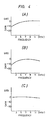
- Fig. 2(1) shows the spark timing waveform.
- the waveform signal is the base signal to the power transistor 134 of the ignition control device 103.
- the power transistor 134 is turned ON at an H level and is turned off at an L level.
- the spark is generated by the ignition coil 135 in the transient period in which the transistor 134 is switched from ON to OFF.
- Fig, 2(2) shows the output signal of a predetermined pulse width of the monostable circuit 128 which receives the base signal as the input and is triggered when the transistor changes from ON to OFF thereby to generate a pulse signal of a predetermined width t 1 .
- Fig. 2(3) shows the boosted output of the knock sensor 100.
- the signals detected by the knock sensor 100 are those which change to positive and negative with a d.c.
- Fig. 2(6) shows the knock signal detected by the comparator 118 and fig. 2(7) is a partially enlarged view of this knock signal. If the operation of the comparator 138 is hereby neglected, the integration circuit 125 receives the output signal of the retard angle setting circuit 126 and integrates the pulse only when the pulse is at the high level "1" (fig. 2(7)). Accordingly, an integration value corresponding to the number of pulses is produced from the integration circuit 125.
- Fig. 2(8) shows the output of the integration circuit 125. The retard angle control is effected in the retard circuit 132 by means of this output of the integration circuit 125.
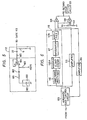
- the condenser coupling circuit 112 consists of a capacitor 22 and a resistor 6.
- the ignition noise cut circuit 113 consists of resistors 5, 14, a Zener diode 31, a capacitor 23, a transistor 28 and an operational amplifier 35.
- the condenser coupling circuit 112 is provided as means for taking out the knock signal from the knock sensor output signal in a satisfactory manner. As the knocking signal is passed through this condenser coupling circuit 112, the d.c. bias voltage overlapping the knock sensor output signal is removed. When only the knock signal is to be taken out from the knock sensor output overlapping the d.c. bias component and when the above-mentioned noise mask is to be applied, the treatment becomes extremely complicated. The concept of d.c. cutting itself is simple and is an extremely practical technique in order to correctly discriminate the knock signal.
- Fig. 5 shows a circuit diagram in which a piezoelectric sensor 100 is disposed in place of the knock sensor using a magnetostriction element. Equivalently, this piezoelectric sensor 100 consists of a capacitor 180.
- the characterizing feature of this construction resides in the connection between the piezoelectric sensor 100 and the capacitor 22. Namely, in this construction, a series circuit of a resistor 181 and a capacitor 182 is disposed and a reference voltage of +3 V is impressed via a high resistor 183 (approx. 1 MO). Furthermore, the reference voltage and the output of the knock sensor 100 via the capacitor 182 are impressed upon the positive terminal of the operation amplifier 184. The reason why the reference voltage is applied via the high resistor 183 is to bring the knock sensor output into the operating range of the operational amplifier 184. The capacitor 182 takes only the a.c. output from the piezoelectric sensor 100.
- the sensor short detector 108 consists of the resistors 9, 10, 11 and the comparator 36.
- the sensor open detector 109 consists of the resistors 7, 8 and the comparator 37. It will hereby be assumed that the potential at point (c) of the comparator 36 is set to approximately 0,2 V and the potential at the point (b) of the comparator 37 to approximately 28 V. If the knock sensor 100 is short-circuited at this instance, the potential at the point (a) becomes approximately 0 V. Accordingly, the potential at the point (a) becomes ,lower than that at the point (c) and the output of the comparator 36 becomes approximately 0 V.
- An advance angle circuit for engine start 201 consists of resistors 68, 69, 70, 59, 61, 57, 58, transistors 73, 75, 78, a Zener diode 81 and a diode 82.
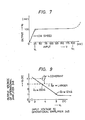
- the transistor 76 is turned ON in synchronism with the knock signal which is the output of the retard angle setting circuit 126. Accordingly, as shown in fig. 2(7), the transistor 76 becomes conductive during the period of the pulse width to of the knock signal (approximately 1 to 1,5 ms) and the current 1 1 flows to the ground from the operational amplifier 85 through the capacitors 72, 71, the resistor 60 and the transisitor 76. The output voltage of the operational amplifier 33 at this time is 3 V.
- the output voltage of the operational amplifier 85 increases in proportion to the mumber of the knocking pulses, i.e the pulse width to.
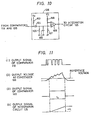
- Fig. 15 shows the operation waveform diagram when the abnormal voltage overlaps at point (a) of fig. 13. This detection of an abnormal voltage is effected with the detectors 108 and 109 which act also as detectors of abnormal voltage.
- Fig. 15 (1) shows the base signal of the power transistors 134. If for any reason the knock sensor 100 produces an abnormal signal, voltages higher than the voltage at point (b) are continuously produced as shown in fig. 15(2) so that the output of the comparator 37 continuously drops to 0 V as shown in fig. 15(3). Consequently, the output of the integration circuit 125 such as shown in fig. 15(4) is first increasing and is then clamped to the fail-safe clamp voltage (5, 4 V in the drawing). Accordingly, the operation of the circuit is not adversely affected by abnormal voltages.
Landscapes
- Engineering & Computer Science (AREA)
- Chemical & Material Sciences (AREA)
- Combustion & Propulsion (AREA)
- Signal Processing (AREA)
- Mechanical Engineering (AREA)
- General Engineering & Computer Science (AREA)
- Physics & Mathematics (AREA)
- General Physics & Mathematics (AREA)
- Electrical Control Of Ignition Timing (AREA)
Claims (3)
Applications Claiming Priority (3)
| Application Number | Priority Date | Filing Date | Title |
|---|---|---|---|
| JP11099980A JPS5738667A (en) | 1980-08-14 | 1980-08-14 | Knock controller |
| JP110999/80 | 1980-08-14 | ||
| EP81106002A EP0047394B1 (de) | 1980-08-14 | 1981-07-30 | Vorrichtung zur Kontrolle des Klopfens von Brennkraftmaschinen |
Related Parent Applications (1)
| Application Number | Title | Priority Date | Filing Date |
|---|---|---|---|
| EP81106002.9 Division | 1981-07-30 |
Publications (4)
| Publication Number | Publication Date |
|---|---|
| EP0148308A2 EP0148308A2 (de) | 1985-07-17 |
| EP0148308A3 EP0148308A3 (en) | 1987-01-21 |
| EP0148308B1 true EP0148308B1 (de) | 1990-06-13 |
| EP0148308B2 EP0148308B2 (de) | 1995-04-05 |
Family
ID=26081077
Family Applications (1)
| Application Number | Title | Priority Date | Filing Date |
|---|---|---|---|
| EP84103812A Expired - Lifetime EP0148308B2 (de) | 1980-08-14 | 1981-07-30 | Klopfkontrollvorrichtung für Brennkraftmaschinen |
Country Status (2)
| Country | Link |
|---|---|
| EP (1) | EP0148308B2 (de) |
| DE (1) | DE3177108D1 (de) |
Families Citing this family (4)
| Publication number | Priority date | Publication date | Assignee | Title |
|---|---|---|---|---|
| US4761992A (en) * | 1987-06-09 | 1988-08-09 | Brunswick Corporation | Knock detection circuit with gated automatic gain control |
| DE3901564A1 (de) * | 1989-01-20 | 1990-08-02 | Audi Ag | Verfahren zum betreiben einer klopfgeregelten brennkraftmaschine |
| US5421191A (en) * | 1993-03-08 | 1995-06-06 | Chrysler Corporation | Knock sensor diagnostic system |
| DE10150377A1 (de) * | 2001-10-11 | 2003-04-17 | Bosch Gmbh Robert | Verfahren und Vorrichtung zur Kurzschlusserkennung von Signalleitungen eines Sensors, insbesondere eines Klopfsensors für eine Brennkraftmaschine |
Family Cites Families (5)
| Publication number | Priority date | Publication date | Assignee | Title |
|---|---|---|---|---|
| US4240388A (en) * | 1977-09-19 | 1980-12-23 | Nippondenso Co., Ltd. | Method for controlling timing of spark ignition for an internal combustion engine |
| US4111035A (en) * | 1977-11-07 | 1978-09-05 | General Motors Corporation | Engine knock signal generating apparatus with noise channel inhibiting feedback |
| IT1088734B (it) * | 1977-12-06 | 1985-06-10 | Snam Progetti | Sistema automatico di sopressione del rumore di fondo su apparecchiature per la misura del battito in testa |
| DE3069821D1 (en) * | 1979-05-25 | 1985-01-31 | Hitachi Ltd | Method and apparatus for controlling the ignition timing of internal combustion engines |
| DE3022307C2 (de) * | 1979-06-15 | 1986-02-20 | Nissan Motor Co., Ltd., Yokohama, Kanagawa | Zündzeitpunkt-Steuereinrichtung |
-
1981
- 1981-07-30 DE DE8484103811T patent/DE3177108D1/de not_active Expired
- 1981-07-30 EP EP84103812A patent/EP0148308B2/de not_active Expired - Lifetime
Also Published As
| Publication number | Publication date |
|---|---|
| EP0148308B2 (de) | 1995-04-05 |
| EP0148308A3 (en) | 1987-01-21 |
| EP0148308A2 (de) | 1985-07-17 |
| DE3177108D1 (en) | 1989-11-02 |
Similar Documents
| Publication | Publication Date | Title |
|---|---|---|
| EP0146668B1 (de) | Kontrollvorrichtung für das Klopfen in Verbrennungsmaschinen | |
| US4111035A (en) | Engine knock signal generating apparatus with noise channel inhibiting feedback | |
| US4599982A (en) | Knock control apparatus for internal combustion engines | |
| US4333334A (en) | Knocking discrimination apparatus | |
| US5866808A (en) | Apparatus for detecting condition of burning in internal combustion engine | |
| US4528955A (en) | Knock control system | |
| EP0148308B1 (de) | Klopfkontrollvorrichtung für Brennkraftmaschinen | |
| US6889655B1 (en) | Device for controlling the ignition timing for internal combustion engines | |
| US4476709A (en) | Knock detecting apparatus for internal combusion engines | |
| JPS5965225A (ja) | 内燃機関のノツキング検出装置 | |
| US4429565A (en) | Knocking detecting apparatus for an internal combustion engine | |
| US4454750A (en) | Apparatus for generating a knock signal for use with an internal combustion engine | |
| JPH0136567B2 (de) | ||
| JPS6326278B2 (de) | ||
| JP3199662B2 (ja) | 内燃機関のノッキング検出装置 | |
| JPS6122141B2 (de) | ||
| JP3101234B2 (ja) | 内燃機関のイオン電流検出装置 | |
| EP0055298A1 (de) | Zündzeitpunkt-steuereinrichtung für eine brennkraftmaschine | |
| EP0071472B1 (de) | Kontaktloses Zündsystem für Brennkraftmaschine | |
| JPS6350548B2 (de) | ||
| JPS6060034B2 (ja) | ノツク制御装置 | |
| US4351282A (en) | Ignition timing control system for internal combustion engine | |
| EP0366681A1 (de) | Klopfdetektorschaltung mit automatischer verstärkungsfaktorsteuerung während eines messfensters | |
| JPS5813159A (ja) | ノツク制御装置 | |
| JPH11315775A (ja) | イオン電流検出装置 |
Legal Events
| Date | Code | Title | Description |
|---|---|---|---|
| PUAI | Public reference made under article 153(3) epc to a published international application that has entered the european phase |
Free format text: ORIGINAL CODE: 0009012 |
|
| 17P | Request for examination filed |
Effective date: 19840412 |
|
| AC | Divisional application: reference to earlier application |
Ref document number: 47394 Country of ref document: EP |
|
| AK | Designated contracting states |
Designated state(s): DE FR GB |
|
| PUAL | Search report despatched |
Free format text: ORIGINAL CODE: 0009013 |
|
| AK | Designated contracting states |
Kind code of ref document: A3 Designated state(s): DE FR GB |
|
| 17Q | First examination report despatched |
Effective date: 19880725 |
|
| GRAA | (expected) grant |
Free format text: ORIGINAL CODE: 0009210 |
|
| AC | Divisional application: reference to earlier application |
Ref document number: 47394 Country of ref document: EP |
|
| AK | Designated contracting states |
Kind code of ref document: B1 Designated state(s): DE FR GB |
|
| REF | Corresponds to: |
Ref document number: 3177191 Country of ref document: DE Date of ref document: 19900719 |
|
| ET | Fr: translation filed | ||
| PLBI | Opposition filed |
Free format text: ORIGINAL CODE: 0009260 |
|
| 26 | Opposition filed |
Opponent name: ROBERT BOSCH GMBH Effective date: 19910305 |
|
| PUAH | Patent maintained in amended form |
Free format text: ORIGINAL CODE: 0009272 |
|
| STAA | Information on the status of an ep patent application or granted ep patent |
Free format text: STATUS: PATENT MAINTAINED AS AMENDED |
|
| 27A | Patent maintained in amended form |
Effective date: 19950405 |
|
| AK | Designated contracting states |
Kind code of ref document: B2 Designated state(s): DE FR GB |
|
| ET3 | Fr: translation filed ** decision concerning opposition | ||
| APAC | Appeal dossier modified |
Free format text: ORIGINAL CODE: EPIDOS NOAPO |
|
| APAC | Appeal dossier modified |
Free format text: ORIGINAL CODE: EPIDOS NOAPO |
|
| PGFP | Annual fee paid to national office [announced via postgrant information from national office to epo] |
Ref country code: FR Payment date: 20000622 Year of fee payment: 20 |
|
| PGFP | Annual fee paid to national office [announced via postgrant information from national office to epo] |
Ref country code: GB Payment date: 20000627 Year of fee payment: 20 |
|
| PGFP | Annual fee paid to national office [announced via postgrant information from national office to epo] |
Ref country code: DE Payment date: 20000929 Year of fee payment: 20 |
|
| PG25 | Lapsed in a contracting state [announced via postgrant information from national office to epo] |
Ref country code: GB Free format text: LAPSE BECAUSE OF EXPIRATION OF PROTECTION Effective date: 20010729 |
|
| REG | Reference to a national code |
Ref country code: GB Ref legal event code: PE20 Effective date: 20010729 |
|
| APAH | Appeal reference modified |
Free format text: ORIGINAL CODE: EPIDOSCREFNO |