EP0147184B1 - Flat glass sight gauge - Google Patents
Flat glass sight gauge Download PDFInfo
- Publication number
- EP0147184B1 EP0147184B1 EP84308944A EP84308944A EP0147184B1 EP 0147184 B1 EP0147184 B1 EP 0147184B1 EP 84308944 A EP84308944 A EP 84308944A EP 84308944 A EP84308944 A EP 84308944A EP 0147184 B1 EP0147184 B1 EP 0147184B1
- Authority
- EP
- European Patent Office
- Prior art keywords
- backing plate
- glass
- plate means
- trough
- block
- Prior art date
- Legal status (The legal status is an assumption and is not a legal conclusion. Google has not performed a legal analysis and makes no representation as to the accuracy of the status listed.)
- Expired
Links
- 239000005357 flat glass Substances 0.000 title claims description 15
- 239000011521 glass Substances 0.000 claims description 84
- 239000007788 liquid Substances 0.000 claims description 28
- 239000002184 metal Substances 0.000 claims description 24
- 238000007789 sealing Methods 0.000 claims description 13
- 230000008878 coupling Effects 0.000 claims description 10
- 238000010168 coupling process Methods 0.000 claims description 10
- 238000005859 coupling reaction Methods 0.000 claims description 10
- 239000012530 fluid Substances 0.000 claims description 2
- 230000002787 reinforcement Effects 0.000 claims description 2
- 239000003566 sealing material Substances 0.000 claims description 2
- 230000006835 compression Effects 0.000 claims 1
- 238000007906 compression Methods 0.000 claims 1
- 238000009434 installation Methods 0.000 description 16
- 238000010276 construction Methods 0.000 description 8
- 239000011324 bead Substances 0.000 description 7
- 238000004891 communication Methods 0.000 description 3
- 210000001503 joint Anatomy 0.000 description 3
- 210000004907 gland Anatomy 0.000 description 2
- 238000010079 rubber tapping Methods 0.000 description 2
- 239000005336 safety glass Substances 0.000 description 2
- 240000005020 Acaciella glauca Species 0.000 description 1
- 241000538562 Banjos Species 0.000 description 1
- 230000004308 accommodation Effects 0.000 description 1
- 238000006243 chemical reaction Methods 0.000 description 1
- 239000000446 fuel Substances 0.000 description 1
- 239000000463 material Substances 0.000 description 1
- 239000003921 oil Substances 0.000 description 1
- 230000003287 optical effect Effects 0.000 description 1
- 235000003499 redwood Nutrition 0.000 description 1
- 238000009877 rendering Methods 0.000 description 1
- 238000007493 shaping process Methods 0.000 description 1
- 229910001220 stainless steel Inorganic materials 0.000 description 1
- 239000010935 stainless steel Substances 0.000 description 1
Images


Classifications
-
- G—PHYSICS
- G01—MEASURING; TESTING
- G01F—MEASURING VOLUME, VOLUME FLOW, MASS FLOW OR LIQUID LEVEL; METERING BY VOLUME
- G01F23/00—Indicating or measuring liquid level or level of fluent solid material, e.g. indicating in terms of volume or indicating by means of an alarm
- G01F23/02—Indicating or measuring liquid level or level of fluent solid material, e.g. indicating in terms of volume or indicating by means of an alarm by gauge glasses or other apparatus involving a window or transparent tube for directly observing the level to be measured or the level of a liquid column in free communication with the main body of the liquid
Definitions
- This invention relates to liquid level gauges incorporating a plurality offlat sight glasses of the kind in which a liquid whose level is to be measured, is adapted to be brought into contact with a prismatically grooved or fluted face of a heavy pressure resistant safety glass usually in the form of a thick block.
- a flat glass is to be distinguished from a tubular sight glass and provides an optical effect, whereby the appearance of the glass is silvery in the space above the liquid, but black where liquid is present. This contrast is very helpful in rendering visible the level of even colourless liquids.
- gauges having such flat sight glasses are to be found in the prior art, in US-A-1 082441; US-A-1 181 139; US-A-1 183 872; US-A-1 954 466; US-A-2 326 449; and US-A-2 608 095; and an individual sight glass for use in such a gauge is described in BE-A-546 786.
- each sight glass consists of a block of heavy safety glass with a prismatically grooved or fluted face on the liquid side, and each such block is clamped with intervening seals or gaskets between a metal windowed cover plate means and a metal backing plate means.
- the backing plate means Behind each sight glass the backing plate means is recessed and defines with the fluted face of the glass, a passage in which the liquid. whose level is to be viewed. rises and falls.
- wedge means are used to secure the glass sandwiched between the cover plate and the backing plate; while in US-A-1 183 872, the cover plate means and the backing plate means are integral with one another.
- the flat glass sight gauge known, for example from the specification of the aforementioned US-A-1 181 139, has two such sight glasses which are arranged in alignment, but these are well spaced apart.
- Sight gauge constructions are known in which the sight tubes terminate in banjo-type pipe couplings or unions which are fitted over cylindrical pipes having bores communicating with the interiors of liquid containers; or the banjo-type couplings may be fitted over cylindrical parts of valve bodies, screwed into tank walls or into bosses formed on such walls of containers or tanks.
- banjo-type couplings There are many installations of gauges in existence with banjo-type couplings of the kind referred to, but fitted with round glass tubes. It is one purpose of the present invention to allow conversion of gauge installations, from, round to flat glass sight tubes, with an execution which will meet up to date official requirements for flat glass gauges. Accordingly, it is a further intention that the gauge proposed, at least in some embodiments thereof, should be capable of being equipped with one or more end. fittings of the kind comprising banjo-type couplings, such as will inter-fit with existing cylindrical tank fittings, which may be valve bodies screwed into suitable tank bosses.
- the invention provides a flat glass sight gauge of the kind comprising at least two sight glasses in alignment each sight glass being constituted by a glass block having on its liquid side. longitudinally extending prismatic flutes or grooves, and each glass block being sandwiched between a cover plate means and a backing plate means, which is characterized in that two or more such sight glasses are aligned end to end in close proximity and are connected for sealed liquid flow in series, this being achieved by each glass block being formed.
- Each said glass block has a said trough on one of its major faces, and preferably, the trough is surrounded by a continuous substantially planar marginal portion of that face, which trough has a base provided with the said longitudinal prismatic grooves; seal means being disposed to surround the said trough and to form a seal between a said substantially planar marginal face portion of each said glass block and a said substantially flat frontal face of said metal backing plate means; each glass block being secured against the flat frontal face of the backing plate means by being sandwiched between the backing plate means and a said metal cover plate means, and wherein at each junction between adjacent ends of aligned glass blocks, there is secured by some of said screw-threaded bolt means to a reverse face of the backing plate means, a said rigid metal connector block, the said backing plate means being apertured at or towards each end of each said trough to afford holes leading to the two troughs at or near their adjacent ends; and said metal connector block having a duct giving sealed intercommunication between the holes leading to the ends of the adjacent
- the gauge according to this proposal allows for efficient sealing of all the liquid passages of the gauge and for structural integrity of the gauge assembly. enabling it to withstand rough handling, vibration and severe changes of pressure and temperature; a particular advantage which is achieved by the construction now proposed. being that efficient sealing may be accomplished by interposing sealing strips or gaskets between surfaces which are planar and continuous over the whole area of each seal.
- This sealing efficiency is obtainable firstly, in the case of the seal between the flat sight glasses and the flat frontal face of the backing plate means, which seals can completely surround the mouth of the liquid receiving trough in each glass; and secondly, in the case of seals or gaskets interposed between the backing plate on its reverse side, and the connector blocks.
- These flat surfaces can be made to bring pressure evenly on to the whole area of each seal or gasket, suitably by employing the same bolt means which are used to secure the cover plate means, the sight glasses and the connnector block means to the backing plate means.
- the invention affords a versatile sight gauge installation which may have a length ranging up to 4 metres or more, the structural integrity of the installation being provided mainly by the backing plate.
- the rigid metal connector blocks bolted to the rear of the backing plates, form a structural bridge between the aligned backing plates.
- the connector blocks provide liquid inter-communication, with efficient sealing, between adjacent aligned glasses.
- the cover plate means which are bolted to the backing plate contributes to the structural strength of the installation, the glasses themselves being largely relieved of stress. This structural strength enables the installation to withstand vibration, rough handling and changes of pressure and temperature.
- the versatility may be enhanced by C-clamps for securing the installation to a tank wall, being adjustable longitudinally of the backing plate; while provision for positional adjustment of its end fittings is also provided for, as is the equipping of the gauge with the ability to have end fittings of any required type attached to rigid end connector blocks or pipes leading therefrom.
- the backing plate of the gauge according to the invention is preferably U or channel-shaped in cross-section, so as to be structurally stiff, and it may be longitudinally co-extensive with at least two such glass blocks secured to its frontal face in end to end alignment; or, a plurality of backing plates may be arranged in end to end alignment, each backing plate having a single glass block secured on its frontal face.
- a said metal connecting block will be provided at each junction between adjacent aligned glass blocks.
- the connector blocks in some cases, may form structural connections between separate backing plate sections which are aligned end to end in close proximity.
- the cover plate which is bolted to the backing plate has lateral flanges which butt with the backing plate on tightening the bolts so as to limit excessive transverse flexing of the backing plate.
- Each said cover plate may be longitudinally co-extensive with at least two glass blocks arranged end to end in alignment.
- the gauge is provided at one or both of its ends with a banjo-type pipe coupling for providing liquid flow inter- communication between the adjacent end of a sight glass trough, and the bore of a pipe communicating with the interior of a liquid container.
- the trough and said pipe bore will extend approximately at right angles to one another, and said banjo-type coupling .will surround the bore of the said pipe.
- Means are provided whereby the distance between the banjo-type pipe coupling and the trough is adjust- ably variable. in the direction in which the trough extends longitudinally.
- At least one endless strip 12 of sealing material is disposed to surround each trough 15 and to form a seal between the substantially planar face portion 14 of each glass block 10 and a frontal planar face of a metal backing plate 13.
- the backing plate 13 has lateral flanges 113 so that it is U-shaped as seen in Figure 3; this U or channel- shape gives the backing plate a configuration of great structural stiffness.
- Clamping means. for clamping each said sighting glass to a said backing plate 13 comprise a cover plate 21 secured to the backing plate 13 on bolts 26 being tightened. Strips 22 of cushioning material are interposed between the glass 10 and the cover plate 21.
- the cover plate 21 has lateral flanges 23 which may abut with the backing plate 13; the flanges also prevent flexing of the plate 13 when the bolts 26 are tightened.
- gauge assembly when bolted up will be afforded structural stiffness and strength, by the channel configuration given to both the backing plate 13 and to the cover plate 21.
- Each cover plate 21 may be co-extensive with two glass blocks 10, disposed aligned end to end, and in the example shown in Figure 1, the backing plate 13 is also co-extensive with the two blocks 10 forming the sight glasses la and lb.
- the cover plate 21 has oblong windows 27 through which the glasses are exposed to view.
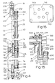
- Each said backing plate 13 is apertured at or towards each end of the trough 15 in each block 10, and conduit means in the form of connector blocks generally designated 16, (see Figure 4), are sealed over the rear of each said aperture so as to give sealed intercommunication between adjacent ends of successive troughs 15, intermediate the ends of the gauge.
- further connector blocks 16 are provided to give sealed liquid flow intercommunication between the ends of the troughs 15 and two gauge end fittings, generally designated 17 and 18.
- 100 represents the wall of a tank or container.
- a boss 101 is welded at 102 to the tank wall 100, and the boss has a through bore 103, which will communicate through a hole in wall 100 (not shown) with the interior of the tank.
- 10 indicates a glass block of a sight gauge and the block 10 defines a trough 15 extending over a frontal face of the backing plate 13. Adjacent the end of the trough 15 the backing plate is apertured at 130.
- Bolted to the rear of the backing plate 13 is a connector block 131 which contains a passage 132 which communicates with the hole 130 and with the trough 15.
- 133 is a seal at the mouth of the hole 130.
- the block 131 has a banjo-type extension 134 (see also Figures 1 and 2) which fits over a cylindrical extension 107 of the boss 101.
- This cylindrical extension 107 defines the bore 103 and has also radial bores 108 which provide communication between the bore 103 and the passage 132 in the connector block 131.
- the extension 107 of the boss (which may be an existing valve or like fitting provided on the wall of a tank or container) is threaded to receive nuts 139 and 140 for clamping the banjo-type extension 134 of the connector block 131.
- 109 generally represents a tap screw which may be employed to drain the contents of the sight gauge.
- the upper end fitting 18 in Figure 4 comprises a connector block 231 bolted to the rear face of backing plate 13, and having a passage 232 communicating with the trough 15 through a hole 230 in the backing plate 13.
- a pipe 234 is secured by a gland nut 235 to a fitting 236 threadedly secured to the block 231.
- 233 is a seal at the mouth of the hole 230 in the backing plate 13, the seal being seated in a recess formed for the purpose in the connector block 231.
- the upper end fitting in Figure 16 is somewhat similar to that shown in Figure 4, except that the pipe 234 is adjustable longitudinally relative to the connector block 231, such adjustability being permitted by a gland nut 235 which in this case is threaded to a tapped hole in the block 231 to urge a seal ring 237 backed up by a washer 239 to seal between the pipe and the block 231 which has a frusto-conically tapering bore in this region.
- the pipe 234 leads to a banjo extension 334 which surrounds a spigot 336.
- the spigot 336 is cylindrical and forms part of a hollow plug 337 which is threaded in a boss 401 secured by welds 402 to a tank wall 100.
- the spigot 336 has an axial bore 403 and radial bores 408, which communicate with the bore of the pipe 234.
- the adjustability of the pipe 234 relative to the block 231. will provide accommodation for variations, within predetermined limits, of the preestablished distances between the locations on the tank wall 100, for the bottom fitting 17 and for the upper fitting 18 of Figure 16. Further variation in the distance between such upper and lower locations, already established in the case of existing tanks, will be accommodated by including in the gauge installation, an appropriate number of sighting glasses la, Ib, each of an appropriate length and arranged end to end; these will be provided with intercommunicating means for their respective troughs as will be described below, first with reference to Figures 4 to 6, alternative intercommunicating means being shown in Figures 7 to 15.
- the end fittings 17 and 18 may be seen and understood to provide means for securing the ends of the gauge assembly to the tank wall 100.
- the gauge will be secured by the clamping arrangement depicted in Figure 3.
- 10 again represents the sight glass, and 21 its windowed cover plate, secured by bolts 26 to the backing plate 13, 12 and 22 being interposed sealing strips.
- 23 again designates the lateral flanges of the cover plate 21 which butt with the backing plate 13 to limit flexing of the latter.
- the backing plate 13 itself has lateral flanges 113 which afford its instructural stiffness.
- 114 represents a C-clip secured by bolts 115 to a boss 116, welded to the wall 100 of the tank.
- the C-clip 114 embraces the flanges 113 of the backing plate 13. and is tightened by means of a clamping screw 117 having a nut 118.
- such a clamping arrangement is designated generally at 120 and any number of clamps 120 may be provided, as necessary, over the length of the gauge. such as will locate it securely on the tank wall.
- Such clamps will be adjustable longitudinally of the backing plate so that they may be located appropriately to be bolted to pre positioned bosses 116 welded to the wall 100.
- the clamps might be affixed to threaded sockets by fixing bolts.
- such sockets already existing in the wall 100, and the clamps may need to be appropriately adjusted to suit the locations of these sockets.
- an appropriate number of evenly spaced bosses 116 may be welded in position; or threaded sockets may be provided for receiving bolts 115.
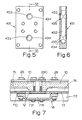
- FIGs 4, 5 and 6 two sight glasses la and Ib are shown aligned with their ends nearly abutting. Each comprises a glass block 10 defining, with a backing plate 13. a trough 15. At the junction between the two glasses 10, means have to be provided for interconnecting the adjacent ends of the two troughs 15. In the embodiment of Figures 4 to 6, these inter onnecting means comprise the connector block 431, shown in Figures 5 and 6, secured by bolts 260 to the reverse face of the backing plate 13 between its lateral flanges 113.
- the backing plate 13 has through holes 130 opening into the troughs 15.
- the connector block 431 has one longitudinal bore 432 and two transverse bores 433, the latter being positioned to align with the holes 130, and having enlarged mouth cavities 434 to receive O-rings 435 for sealing with the backing plate 13 about the mouths of its holes 130.
- the longitudinal bore is closed at one end by a plug 436 its other end being blind.
- the block 431 has tapped holes to receive the ends of bolts 26 and 260, whereby it is secured on the reverse side of the backing plate 13.
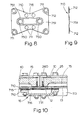
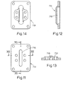
- connector block 731 is shown in Figures 11 to 14. This is employed in the arrangements of intercommunicating means shown in Figures 7 and 10.
- each glass block 10 has its own backing plate, while Figure 7 illustrates a junction in the case of a backing plate which is co-extensive with two glass blocks 10.
- Nuts are shown threaded on thses bolts in these arrangements as illustrated; however the bolts could engage tapped holes in the connector block 731.
- the gasket 710 shown in Figures 8 and 9, has a main body position 718 of planar configuration preformed with holes 711 to allow passage to the bolts as described. It also has two through holes at 750 which are calculated to align with holes 130 of the plate or plates 13 leading to the adjacent ends of aligned troughs 15 in the glass blocks 10.
- the gasket Around the holes 750, the gasket has preformed upstanding annular beads 751; also upstanding are bead portions which, with the beads 751, have an oval configuration in plan view.
- the annular beads of the upper gasket seal about the mouths of the holes 130 in the backing plates 13, while the oval bead of the lower gasket, seals about the mouth of an oval trough 716 of the connector block as best shown in Figure 11.
- the gasket 710 may have short bead portions 712 adjacent its bolt holes 711.
- the sandwich plate 715. of Figure 15 has holes for the bolts and two holes 753 to align with the holes 750 of the gaskets 710.
- the sandwich plate 715 is suitably of stainless steel. as are preferably, each connector block, each cover plate 21 and each backing plate 13.
- each backing plate 13 co-extensive with each glass block 10, but so also is each windowed cover plate 21.
- the bolts 26 secure each block 10 to form a unit with its own backing plate 13 and cover plate 21; the bolts 260 being to secure the extreme ends of the abutting units and to provide an even distribution of pressure upon the whole extent of the seals 12 surrounding each trough and upon the gasket 710 whose bead 751 surrounds the trough 716 in the connector block 731.
- the connector block 731 secured by the bolts 26 and 260 forms the sole structural connection between the two flat glass units aligned end to end, as shown in Figure 10.
- a gauge installation may be shipped complete and fully assembled; or it may be provided as a kit of parts which are easily assembled on site.
- the clamping means provided are adjustable longitudinally of the gauge assembly.
- the end fittings are adjustable to suit the predetermined dimensions of a pre-existing installation so that a new gauge can be fitted instead of an existing one.
- end fitting Although a particular type of end fitting has been described and illustrated, those skilled in the art will appreciate that other types of end fitting. conventional in the art, could be used instead; for example those incorporating bleed taps or valves.
- the glasses and the channel members between which individual glasses are located can be produced in sets each of different lengths, so that, with various lengths suitably combined, a wide range of overall lengths can be achieved.
- the U or channel shaping of the backing plates provides the main contribution to the structural stiffness and strength of the installation.
- the metal connector blocks which are securely bolted to the backing plates, may be employed to form structurally strong connections between adjacent backing plates disposed aligned end to end.
- the glasses themselves are mainly relieved of structural stresses, as are also the C-clamps which merely secure the gauge installation to the wall of the tank or container.
- the gauge now proposed will be found to have a strength/weight characteristic favourably comparable with that of any other gauge of equivalent versatility.
Landscapes
- Physics & Mathematics (AREA)
- Fluid Mechanics (AREA)
- General Physics & Mathematics (AREA)
- Securing Of Glass Panes Or The Like (AREA)
- Filling Or Discharging Of Gas Storage Vessels (AREA)
- Gasket Seals (AREA)
- Insulating Bodies (AREA)
- Insulators (AREA)
Applications Claiming Priority (2)
| Application Number | Priority Date | Filing Date | Title |
|---|---|---|---|
| GB8334305 | 1983-12-23 | ||
| GB838334305A GB8334305D0 (en) | 1983-12-23 | 1983-12-23 | Sight gauge |
Publications (3)
| Publication Number | Publication Date |
|---|---|
| EP0147184A2 EP0147184A2 (en) | 1985-07-03 |
| EP0147184A3 EP0147184A3 (en) | 1985-08-21 |
| EP0147184B1 true EP0147184B1 (en) | 1988-09-21 |
Family
ID=10553751
Family Applications (2)
| Application Number | Title | Priority Date | Filing Date |
|---|---|---|---|
| EP84308944A Expired EP0147184B1 (en) | 1983-12-23 | 1984-12-20 | Flat glass sight gauge |
| EP85900482A Withdrawn EP0165985A1 (en) | 1983-12-23 | 1984-12-20 | Flat glass sight gauge |
Family Applications After (1)
| Application Number | Title | Priority Date | Filing Date |
|---|---|---|---|
| EP85900482A Withdrawn EP0165985A1 (en) | 1983-12-23 | 1984-12-20 | Flat glass sight gauge |
Country Status (7)
| Country | Link |
|---|---|
| US (1) | US4621527A (enExample) |
| EP (2) | EP0147184B1 (enExample) |
| JP (1) | JPS61500867A (enExample) |
| DE (1) | DE3474209D1 (enExample) |
| GB (1) | GB8334305D0 (enExample) |
| NO (1) | NO162681C (enExample) |
| WO (1) | WO1985002904A1 (enExample) |
Families Citing this family (5)
| Publication number | Priority date | Publication date | Assignee | Title |
|---|---|---|---|---|
| US4788929A (en) * | 1988-06-14 | 1988-12-06 | Parker-Hannifin Corporation | Fluid indicator for refrigeration system |
| GB2310722B (en) * | 1996-02-28 | 1999-11-10 | Seetru Ltd | Flat glass sight gauge |
| GB2468887A (en) * | 2009-03-25 | 2010-09-29 | Aes Eng Ltd | Apparatus including a vessel containing a body of liquid essential for the proper functioning of the apparatus |
| US8720269B2 (en) | 2011-05-13 | 2014-05-13 | James H. Haskins | Particulate material monitoring system |
| US8959999B2 (en) | 2011-05-13 | 2015-02-24 | James H. Haskins | Particulate material monitoring system |
Citations (9)
| Publication number | Priority date | Publication date | Assignee | Title |
|---|---|---|---|---|
| BE546786A (enExample) * | ||||
| US231350A (en) * | 1880-08-17 | clough | ||
| US1082441A (en) * | 1913-03-07 | 1913-12-23 | William M Paul | Water-gage-glass column. |
| US1181139A (en) * | 1910-04-07 | 1916-05-02 | George L Huntress Jr | Water-gage. |
| US1183872A (en) * | 1911-04-28 | 1916-05-23 | Edwin P Groff | Gage-glass for registering devices. |
| US1954466A (en) * | 1931-01-07 | 1934-04-10 | Yarnall Waring Co | Water gauge |
| US2326448A (en) * | 1942-09-11 | 1943-08-10 | Ernst Eugene | Knockdown flat offset gauge |
| US2326449A (en) * | 1942-12-29 | 1943-08-10 | Ernst Eugene | Flat offset gauge |
| US2608095A (en) * | 1946-03-06 | 1952-08-26 | Yarnall Waring Co | Flat glass insert assembly |
Family Cites Families (4)
| Publication number | Priority date | Publication date | Assignee | Title |
|---|---|---|---|---|
| GB688581A (en) * | 1951-05-19 | 1953-03-11 | Joseph Charles Copeland | Improved liquid-level indicating gauge glass |
| US2767586A (en) * | 1954-08-31 | 1956-10-23 | Standard Oil Co | Interface level indicator |
| US3358510A (en) * | 1964-11-18 | 1967-12-19 | Oil Rite Corp | Liquid level gauge and method of making a gauge enclosure |
| US4352629A (en) * | 1981-10-19 | 1982-10-05 | United Technologies Corporation | Wind turbine |
-
1983
- 1983-12-23 GB GB838334305A patent/GB8334305D0/en active Pending
-
1984
- 1984-12-20 WO PCT/GB1984/000442 patent/WO1985002904A1/en not_active Ceased
- 1984-12-20 EP EP84308944A patent/EP0147184B1/en not_active Expired
- 1984-12-20 EP EP85900482A patent/EP0165985A1/en not_active Withdrawn
- 1984-12-20 DE DE8484308944T patent/DE3474209D1/de not_active Expired
- 1984-12-20 JP JP60500371A patent/JPS61500867A/ja active Granted
- 1984-12-20 US US06/756,988 patent/US4621527A/en not_active Expired - Lifetime
-
1985
- 1985-08-22 NO NO85853315A patent/NO162681C/no not_active IP Right Cessation
Patent Citations (9)
| Publication number | Priority date | Publication date | Assignee | Title |
|---|---|---|---|---|
| BE546786A (enExample) * | ||||
| US231350A (en) * | 1880-08-17 | clough | ||
| US1181139A (en) * | 1910-04-07 | 1916-05-02 | George L Huntress Jr | Water-gage. |
| US1183872A (en) * | 1911-04-28 | 1916-05-23 | Edwin P Groff | Gage-glass for registering devices. |
| US1082441A (en) * | 1913-03-07 | 1913-12-23 | William M Paul | Water-gage-glass column. |
| US1954466A (en) * | 1931-01-07 | 1934-04-10 | Yarnall Waring Co | Water gauge |
| US2326448A (en) * | 1942-09-11 | 1943-08-10 | Ernst Eugene | Knockdown flat offset gauge |
| US2326449A (en) * | 1942-12-29 | 1943-08-10 | Ernst Eugene | Flat offset gauge |
| US2608095A (en) * | 1946-03-06 | 1952-08-26 | Yarnall Waring Co | Flat glass insert assembly |
Also Published As
| Publication number | Publication date |
|---|---|
| NO162681C (no) | 1990-01-31 |
| NO162681B (no) | 1989-10-23 |
| JPS61500867A (ja) | 1986-05-01 |
| GB8334305D0 (en) | 1984-02-01 |
| EP0165985A1 (en) | 1986-01-02 |
| DE3474209D1 (en) | 1988-10-27 |
| NO853315L (no) | 1985-08-22 |
| EP0147184A3 (en) | 1985-08-21 |
| WO1985002904A1 (en) | 1985-07-04 |
| JPH0466296B2 (enExample) | 1992-10-22 |
| US4621527A (en) | 1986-11-11 |
| EP0147184A2 (en) | 1985-07-03 |
Similar Documents
| Publication | Publication Date | Title |
|---|---|---|
| CA1315644C (en) | Expandable manifold for water delivery system | |
| RU2325624C2 (ru) | Модуль измерительного преобразователя давления с устойчивым к утечке кожухом датчика | |
| US5501472A (en) | Dual compression seal for conduits with compliance to both axial and angular movement | |
| US3995888A (en) | Flexible pipe connector | |
| AU688908B2 (en) | Mounting system for pressure transmitters | |
| US3334928A (en) | Pipe coupling | |
| US4026586A (en) | Plain end pipe joint | |
| US4621527A (en) | Flat glass sight gauge | |
| WO2003027561A1 (en) | An arrangement for monitoring and/or testing of flange joints | |
| US3355193A (en) | Service connection clamp | |
| US4295668A (en) | Adapter for connecting plastic pipe system to cast iron pipe system | |
| US4050700A (en) | Seal having fluent packing material | |
| CN219413901U (zh) | 一种防泄漏的软管接头 | |
| CA1087530A (en) | Leak repair clamp | |
| US5474207A (en) | Liquid storage tank with glass reinforced plastic tie rods | |
| US3331622A (en) | Device for branching-off a secondary piping having a certain diameter, from a main pipe having any diameter | |
| US6173967B1 (en) | Gaskets for fluid conduits | |
| RU2123631C1 (ru) | Фланцевое соединение деталей | |
| US3472537A (en) | Pipe clamp having side outlet | |
| AU2004257931A1 (en) | A hydraulic coupling device and a valve device provided with a sealing member | |
| CA1167027A (en) | Plate-type heat-exchanger and manifold assembly | |
| CN210739993U (zh) | 一种长输油气管道内流体参数检测装置 | |
| US2759360A (en) | Static head compensator for orifice plate companion flanges | |
| US1165388A (en) | Repair device for pipe-lines. | |
| US5590690A (en) | Centering support for double-containment pipe assembly |
Legal Events
| Date | Code | Title | Description |
|---|---|---|---|
| PUAI | Public reference made under article 153(3) epc to a published international application that has entered the european phase |
Free format text: ORIGINAL CODE: 0009012 |
|
| PUAL | Search report despatched |
Free format text: ORIGINAL CODE: 0009013 |
|
| AK | Designated contracting states |
Designated state(s): DE FR GB IT SE |
|
| AK | Designated contracting states |
Designated state(s): DE FR GB IT SE |
|
| 17P | Request for examination filed |
Effective date: 19851203 |
|
| 17Q | First examination report despatched |
Effective date: 19870406 |
|
| GRAA | (expected) grant |
Free format text: ORIGINAL CODE: 0009210 |
|
| ITF | It: translation for a ep patent filed | ||
| AK | Designated contracting states |
Kind code of ref document: B1 Designated state(s): DE FR GB IT SE |
|
| REF | Corresponds to: |
Ref document number: 3474209 Country of ref document: DE Date of ref document: 19881027 |
|
| ET | Fr: translation filed | ||
| PLBE | No opposition filed within time limit |
Free format text: ORIGINAL CODE: 0009261 |
|
| STAA | Information on the status of an ep patent application or granted ep patent |
Free format text: STATUS: NO OPPOSITION FILED WITHIN TIME LIMIT |
|
| 26N | No opposition filed | ||
| ITTA | It: last paid annual fee | ||
| EAL | Se: european patent in force in sweden |
Ref document number: 84308944.2 |
|
| REG | Reference to a national code |
Ref country code: GB Ref legal event code: IF02 |
|
| PGFP | Annual fee paid to national office [announced via postgrant information from national office to epo] |
Ref country code: SE Payment date: 20021216 Year of fee payment: 19 |
|
| PG25 | Lapsed in a contracting state [announced via postgrant information from national office to epo] |
Ref country code: SE Free format text: LAPSE BECAUSE OF NON-PAYMENT OF DUE FEES Effective date: 20031221 |
|
| PGFP | Annual fee paid to national office [announced via postgrant information from national office to epo] |
Ref country code: GB Payment date: 20040120 Year of fee payment: 20 |
|
| PGFP | Annual fee paid to national office [announced via postgrant information from national office to epo] |
Ref country code: DE Payment date: 20040211 Year of fee payment: 20 |
|
| PGFP | Annual fee paid to national office [announced via postgrant information from national office to epo] |
Ref country code: FR Payment date: 20040430 Year of fee payment: 20 |
|
| EUG | Se: european patent has lapsed | ||
| PG25 | Lapsed in a contracting state [announced via postgrant information from national office to epo] |
Ref country code: GB Free format text: LAPSE BECAUSE OF EXPIRATION OF PROTECTION Effective date: 20041219 |
|
| REG | Reference to a national code |
Ref country code: GB Ref legal event code: PE20 |