EP0146972A2 - Adjustable strap fastener - Google Patents
Adjustable strap fastener Download PDFInfo
- Publication number
- EP0146972A2 EP0146972A2 EP84116459A EP84116459A EP0146972A2 EP 0146972 A2 EP0146972 A2 EP 0146972A2 EP 84116459 A EP84116459 A EP 84116459A EP 84116459 A EP84116459 A EP 84116459A EP 0146972 A2 EP0146972 A2 EP 0146972A2
- Authority
- EP
- European Patent Office
- Prior art keywords
- strap
- strap fastener
- sharp corner
- cross bar
- head portion
- Prior art date
- Legal status (The legal status is an assumption and is not a legal conclusion. Google has not performed a legal analysis and makes no representation as to the accuracy of the status listed.)
- Granted
Links
- 229920003002 synthetic resin Polymers 0.000 claims description 4
- 239000000057 synthetic resin Substances 0.000 claims description 4
- 239000000463 material Substances 0.000 abstract description 5
- 230000000717 retained effect Effects 0.000 abstract 1
- 238000003780 insertion Methods 0.000 description 5
- 230000037431 insertion Effects 0.000 description 5
- 238000006073 displacement reaction Methods 0.000 description 4
- 230000004048 modification Effects 0.000 description 4
- 238000012986 modification Methods 0.000 description 4
- 230000000694 effects Effects 0.000 description 3
- 238000010276 construction Methods 0.000 description 2
Images


Classifications
-
- A—HUMAN NECESSITIES
- A44—HABERDASHERY; JEWELLERY
- A44B—BUTTONS, PINS, BUCKLES, SLIDE FASTENERS, OR THE LIKE
- A44B17/00—Press-button or snap fasteners
-
- A—HUMAN NECESSITIES
- A44—HABERDASHERY; JEWELLERY
- A44B—BUTTONS, PINS, BUCKLES, SLIDE FASTENERS, OR THE LIKE
- A44B11/00—Buckles; Similar fasteners for interconnecting straps or the like, e.g. for safety belts
- A44B11/02—Buckles; Similar fasteners for interconnecting straps or the like, e.g. for safety belts frictionally engaging surface of straps
- A44B11/04—Buckles; Similar fasteners for interconnecting straps or the like, e.g. for safety belts frictionally engaging surface of straps without movable parts
-
- Y—GENERAL TAGGING OF NEW TECHNOLOGICAL DEVELOPMENTS; GENERAL TAGGING OF CROSS-SECTIONAL TECHNOLOGIES SPANNING OVER SEVERAL SECTIONS OF THE IPC; TECHNICAL SUBJECTS COVERED BY FORMER USPC CROSS-REFERENCE ART COLLECTIONS [XRACs] AND DIGESTS
- Y10—TECHNICAL SUBJECTS COVERED BY FORMER USPC
- Y10T—TECHNICAL SUBJECTS COVERED BY FORMER US CLASSIFICATION
- Y10T24/00—Buckles, buttons, clasps, etc.
- Y10T24/40—Buckles
- Y10T24/4002—Harness
- Y10T24/4012—Clamping
- Y10T24/4014—One-piece
-
- Y—GENERAL TAGGING OF NEW TECHNOLOGICAL DEVELOPMENTS; GENERAL TAGGING OF CROSS-SECTIONAL TECHNOLOGIES SPANNING OVER SEVERAL SECTIONS OF THE IPC; TECHNICAL SUBJECTS COVERED BY FORMER USPC CROSS-REFERENCE ART COLLECTIONS [XRACs] AND DIGESTS
- Y10—TECHNICAL SUBJECTS COVERED BY FORMER USPC
- Y10T—TECHNICAL SUBJECTS COVERED BY FORMER US CLASSIFICATION
- Y10T24/00—Buckles, buttons, clasps, etc.
- Y10T24/40—Buckles
- Y10T24/4072—Pivoted lever
- Y10T24/4077—Looped strap
-
- Y—GENERAL TAGGING OF NEW TECHNOLOGICAL DEVELOPMENTS; GENERAL TAGGING OF CROSS-SECTIONAL TECHNOLOGIES SPANNING OVER SEVERAL SECTIONS OF THE IPC; TECHNICAL SUBJECTS COVERED BY FORMER USPC CROSS-REFERENCE ART COLLECTIONS [XRACs] AND DIGESTS
- Y10—TECHNICAL SUBJECTS COVERED BY FORMER USPC
- Y10T—TECHNICAL SUBJECTS COVERED BY FORMER US CLASSIFICATION
- Y10T24/00—Buckles, buttons, clasps, etc.
- Y10T24/40—Buckles
- Y10T24/4086—Looped strap
-
- Y—GENERAL TAGGING OF NEW TECHNOLOGICAL DEVELOPMENTS; GENERAL TAGGING OF CROSS-SECTIONAL TECHNOLOGIES SPANNING OVER SEVERAL SECTIONS OF THE IPC; TECHNICAL SUBJECTS COVERED BY FORMER USPC CROSS-REFERENCE ART COLLECTIONS [XRACs] AND DIGESTS
- Y10—TECHNICAL SUBJECTS COVERED BY FORMER USPC
- Y10T—TECHNICAL SUBJECTS COVERED BY FORMER US CLASSIFICATION
- Y10T24/00—Buckles, buttons, clasps, etc.
- Y10T24/40—Buckles
- Y10T24/4088—One-piece
- Y10T24/4093—Looped strap
Definitions
- This invention relates to a strap fastener for adjustably connecting a strap, belt or band to a variety of articles.
- Advanced such fasteners are made of a plastic material formed into an integrally molded structure which generally comprises a pair of opposing side flanges, a grip end portion at the one ends of the side flanges, an anchor end portion at the opposite ends of the side flanges and a plurality of parallel cross bars disposed in between the grip and anchor end portions and extending transversely across between the side flanges.
- one end portion of a strap or the like is looped about one of the cross bars, passed under the anchor end of the fastener and secured in place as by rivetting.
- the other end portion of the strap which is adapted for length adjustment is looped about another cross bar, passed under the grip end of the fastener and gripped therebetween against displacement.
- the gap therebetween is desirably the larger the better. Conversely, however, the larger the gap, the tendency will be greater for the strap to get loose under tension. Vice versa, this tendency is less the smaller the gap, but the insertion of the strap becomes more difficult.
- the present invention seeks to provide an adjustable strap fastener made of a plastic material which is simple in construction and reliable in operation.
- the present invention further seeks to provide an adjustable strap fastener which is relatively low in profile, yet capable of easy insertion of a strap or the like but resistant to force tending to loosen the strap from the adjustable strap fastener.
- the present invention seeks to provide an adjustable strap fastener which has multi-point stops for the strap to hold the same against displacement under heavy tension.
- the present invention further seeks to provide an adjustable strap fastener capable of holding a strap or the like against displacement with a holding'force which increases as a tension on the strap or the like becomes greater.
- the present invention further seeks to provide an adjustable strap fastener which can be manipulated with utmost ease.
- a strap fastener molded on synthetic resin for adjustably connecting ends of a strap or the like comprising: a grip head portion; a pair of parallel spaced side flange portions extending from said grip head portion in a common direction and having respective bottom surfaces; a connecting portion extending perpendicularly to said side flange portions to interconnect them at their distal ends; and a pair of parallel spaced first and second cross bars extending parallel to said connecting portion and joined with said side flange portions, said first cross bar being disposed adjacent to said grip head portion, said grip head portion having a first sharp corner edge disposed adjacent to said first cross bar and lying flush with said bottom surfaces of said side flange portions, characterized in that said first cross bar has a first projection extending toward said grip head portion and terminating in a second sharp corner edge, and a second projection extending toward said connecting portion and terminating in a third sharp corner edge, said first projection having a top surface and a flat bottom surface merging together to jointly define said second sharp corner
- FIGS 1 through 8 show an adjustable strap fastener generally designated 10 according to one embodiment of the present invention.
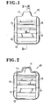
- the strap fastener 10 is made of a synthetic resin or plastic material formed into an integral molded construction generally rectangular in shape as shown in Figures 1 and 2.
- the strap fastener 10 comprises a grip head portion 11 at one of its ends, a connecting portion 12 at the other end, a pair of opposed side flange portions 13, 14 extending longitudinally between and secured to opposite ends of the head portion 11 and the connencting portion 12, a first cross bar 15 adjacent to the head portion 11, and a second cross bar 16 adjacent to the connecting portion 12, the cross bars 15 and 16 extending in spaced parallel relation to each other between and connected to the opposed side flanges 13 and 14.
- the head portion 11, as shown in Figure 5, includes a projecting tab lla of reduced thickness, a bevelled portion lla' extending downwardly from the tab lla at an angle, and a lower portion llb extending from the bevelled portion lla' downwardly substantially at a right angle to the plane of the fastener 10 adjacent the first cross bar 15, the lower portion llb terminating with a flat bottom surface llc lying flush with the bottom surfaces of the opposed side flanges 13, 14.
- the flat bottom surface llc has a sharp corner lld which serves as a first strap stop as later described.
- the side flanges 13, 14 are tapered from the region of the second cross bar 16 toward the connecting portion 12.
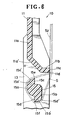
- the first cross bar 15 includes a pair of integral top and bottom portions 15a, 15b displaced from one another in a direction parallel to the side flange portions 13 so as to provide a pair of first and second projections 15a', 15b'.
- the first projection 15a' extends toward the grip head portion 11 and terminates in a second sharp corner edge 15e which is defined jointly by a flat bottom surface 15c and an arcuate top surface 15c', while the second projection 15b' extends toward the connecting portion 12 and terminates in a third sharp corner edge 15f which is defined jointly by a flat top surface 15d and an arcuate bottom suraface 15d'.
- the flat bottom surface 15c of the first projection 15a' and the flat top surface 15d of the second projection 15b' extend in opposite directions from substantially the midpoint of the thickness of the cross bar 15, and also in a plane substantially parallel to the general plane of the fastener 10, the flat surfaces 15c, 15d lying slightly above the middle of the height of the side flange portion 13.
- the second sharp corner edge 15e as viewed from the plan, is spaced from the first sharp corner edge 11d by a distance larger than the thickness of the strap S.
- the second and third sharp corner edges 15e, 15f serve as second and third stops as later described.
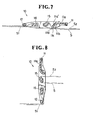
- the strap or belt S so inserted into the strap fastener 10 first with one of its ends designated S 1 looped about the second cross bar 16 and passed underneath the connecting portion 12, the extension of the strap S at this end being secured in place as by rivetting or stitching.
- the other end of the strap designated S 2 is then looped about the first cross bar 15 and passed underneath the lower portion 11b of the head 11, in which instance the leading end portion of the strap S 2 is brought into contact with the flat bottom surface llc.
- the strap end S2 is adjustable in length to suit the particular application. This adjustment may be made by pulling out the leading strap end S 2 to shorten the effective length of the strap S as disposed in the condition of Figure 7, or, shown in Figure 8, by rotating the fastener 10 counter-clockwise about the connecting portion 12 to release the strap end S 2 and thereby pulling the strap S out to shorten or to lengthen the effective length of the strap S as desired.
- the strap fastener 10 thus constructed is, as shown in Figure 6, provided with multi-point stops, namely, at corners lld, 15e and 15f along the path of the strap S 2 which is to be adjusted in length, so that the strap. S is firmly held against displacement which would otherwise occur under the influence of heavy tension exerted in use.
- This multi-point stop arrangement permits an increase in the gap between the grip head 11 and the first cross bar 15 to facilitate insertion of the strap.
- Another advantage of the present structure is that the strap fastener 10 can be made to present a relatively low profile, which is aesthetically and economically desirable.
- Figures 9 and 10 illustrates a modification of the strap fastener 10 already described in which the only addition is the provision of alternate ridges 17 and grooves 18 for the regions of the head 11 with which the strap S comes in direct contact when mounted in normal use.
- Such regions comprise the flat bottom surface llc, the arcuate top surface portion 15a and the bottom portion 15b. More specifically, the bottom surface llc has throughout the length thereof the ridges 17 and the grooves 18 extending parallel to the side flange portion 13.
- the ridges 17 and the grooves 18 are also provided at the sharp corners 15e, 15f of the first cross bar 15 and extend normal to the general plane of the fastener 10. This ridge-and-groove arrangement gives a rise to the effect of gripping the inserted strap S.
- Figures 11, 12 and 13 inclusive show another modification in which the lower portion portion llb of the head 11 extends toward the first cross bar 15 in parallel relation to the side flange portion 13 with the result that the bottom surface llc is enlarged also toward the first cross bar 15, the arrangement being conceived to improve the gripping effect.
- the sharp corner lid of the lower portion portion llb is spaced from the sharp corner 15e of the cross bar 15, as viewed from the plan, by a distance which is larger than the thickness of the strap or belt S.
- the ridge-and-groove arrangement of Figures 9 and 10 may also be combined to further enhance the gripping effect.
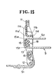
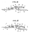
- Figures 14, 15, 16 and 17 inclusive show a further modification of the strap fastener 10 in which the first cross bar 15, the second cross bar 16 and the connecting portion 12 are disposed out of alignment with respect to the general plane of the strap fastener 10. This is better illustrated in Figure 14 from which it will be understood that the second bar 16 is displaced above the level of the connecting portion 12 and the first cross bar 15 is displaced slightly above the level of the second cross bar 16.
- the connecting portion 12 has a bottom surface lying flush with the bottom surfaces of the side flanges 13, 14.
- the first cross bar 15 is recessed as at 19 throughout the length thereof for saving the amount of synthetic resin material used.
- each of the flange portions 13 is thickened at a region supporting the cross bar 15 and the head portion 11, and the flat surfaces 15e, 15f of the cross bar 15 extend substantially flush with the top surface of the flange portion 13.
- This arrangement provides a tendency for the rotational force upon the connecting portion 12 to orient toward the top of the fastener 10 and for the rotational force upon the lower portion portion llb to orient toward the bottom of the fastener 10. This tendency becomes greater the larger the tension applied to the strap S, thus ensuring firm anchorage of the strap S even when the same is roughly handled.
Landscapes
- Buckles (AREA)
- Purses, Travelling Bags, Baskets, Or Suitcases (AREA)
Abstract
Description
- This invention relates to a strap fastener for adjustably connecting a strap, belt or band to a variety of articles.
- Various adjustable strap fasteners or buckles have been proposed which may be manipulated to adjust the effective length of a strap on for example a bag or a safety seat belt on a motor car.
- Advanced such fasteners are made of a plastic material formed into an integrally molded structure which generally comprises a pair of opposing side flanges, a grip end portion at the one ends of the side flanges, an anchor end portion at the opposite ends of the side flanges and a plurality of parallel cross bars disposed in between the grip and anchor end portions and extending transversely across between the side flanges. In use, one end portion of a strap or the like is looped about one of the cross bars, passed under the anchor end of the fastener and secured in place as by rivetting. The other end portion of the strap which is adapted for length adjustment is looped about another cross bar, passed under the grip end of the fastener and gripped therebetween against displacement. For ease of insertion or passage of the strap between the cross bar and the grip end portion, the gap therebetween is desirably the larger the better. Conversely, however, the larger the gap, the tendency will be greater for the strap to get loose under tension. Vice versa, this tendency is less the smaller the gap, but the insertion of the strap becomes more difficult.
- A proposition is made to thicken the fastener, or to incline the gap defining surfaces instead of enlarging the insertion gap, as disclosed in Japanese Patent Kokai (laid-open) Publication 54-144244. Such attempts are however not satisfactory in that the resulting fastener is costly and becomes unsightly.
- The present invention seeks to provide an adjustable strap fastener made of a plastic material which is simple in construction and reliable in operation.
- The present invention further seeks to provide an adjustable strap fastener which is relatively low in profile, yet capable of easy insertion of a strap or the like but resistant to force tending to loosen the strap from the adjustable strap fastener.
- The present invention seeks to provide an adjustable strap fastener which has multi-point stops for the strap to hold the same against displacement under heavy tension.
- The present invention further seeks to provide an adjustable strap fastener capable of holding a strap or the like against displacement with a holding'force which increases as a tension on the strap or the like becomes greater.
- The present invention further seeks to provide an adjustable strap fastener which can be manipulated with utmost ease.
- According to the present invention, there is provided a strap fastener molded on synthetic resin for adjustably connecting ends of a strap or the like, comprising: a grip head portion; a pair of parallel spaced side flange portions extending from said grip head portion in a common direction and having respective bottom surfaces; a connecting portion extending perpendicularly to said side flange portions to interconnect them at their distal ends; and a pair of parallel spaced first and second cross bars extending parallel to said connecting portion and joined with said side flange portions, said first cross bar being disposed adjacent to said grip head portion, said grip head portion having a first sharp corner edge disposed adjacent to said first cross bar and lying flush with said bottom surfaces of said side flange portions, characterized in that said first cross bar has a first projection extending toward said grip head portion and terminating in a second sharp corner edge, and a second projection extending toward said connecting portion and terminating in a third sharp corner edge, said first projection having a top surface and a flat bottom surface merging together to jointly define said second sharp corner edge, said second projection having a flat top surface and a bottom surface merging together to jointly define said third sharp corner edge, said first and seocnd sharp corner edges, as viewed from the plan, being spaced from one another by a distance larger than the thickness of the strap or the like.
- Many other advantages and features of the present invention will become manifest to those versed in the art upon making reference to the detailed description and the accompanying sheets of drawings in which preferred structural embodiments incorporating the principles of the present invention are shown by way of illustrative example.
- Figure 1 is a front plan view of an adjustable strap fastener according to an embodiment of the present invention;
- Figure 2 is a bottom plan view of the strap fastener of Figure 1;
- Figure 3 is a side elevational view of the strap fastener of Figure 1;
- Figure 4 is a back elevational view of the strap fastener of Figure 1;
- Figure 5 is a cross-sectional view taken along the line V - V of Figure 1;
- Figure 6 is a cross-sectional view on enlarged scale taken along the line VI - VI of Figure 1;
- Figures 7 and 8 are schematic views utilized to explain the operative relations of the strap fastener and the strap;
- Figure 9 is a view similar to Figure 6 but showing another embodiment of the invention;
- Figure 10 is a cross-sectional view taken along the line X - X of Figure 9;
- Figure 11 is a view similar to Figure 1 but showing a further embodiment of the invention;
- Figure 12 is a cross-sectional view taken along the line XII- XII of Figure 11;
- Figure 13 is a cross-sectional view taken along the line XIII - XIII of Figure 11; and
- Figures 14 - 17 inclusive illustrate still another modification of the strap fastener according to the invention.
- Figures 1 through 8 show an adjustable strap fastener generally designated 10 according to one embodiment of the present invention.
- The
strap fastener 10 is made of a synthetic resin or plastic material formed into an integral molded construction generally rectangular in shape as shown in Figures 1 and 2. Thestrap fastener 10 comprises agrip head portion 11 at one of its ends, a connectingportion 12 at the other end, a pair of opposedside flange portions head portion 11 and the connenctingportion 12, afirst cross bar 15 adjacent to thehead portion 11, and asecond cross bar 16 adjacent to the connectingportion 12, thecross bars opposed side flanges - The
head portion 11, as shown in Figure 5, includes a projecting tab lla of reduced thickness, a bevelled portion lla' extending downwardly from the tab lla at an angle, and a lower portion llb extending from the bevelled portion lla' downwardly substantially at a right angle to the plane of thefastener 10 adjacent thefirst cross bar 15, the lower portion llb terminating with a flat bottom surface llc lying flush with the bottom surfaces of theopposed side flanges - The
side flanges second cross bar 16 toward the connectingportion 12. - The
first cross bar 15; as better shown in Figure 6, includes a pair of integral top andbottom portions side flange portions 13 so as to provide a pair of first andsecond projections 15a', 15b'. Thefirst projection 15a' extends toward thegrip head portion 11 and terminates in a secondsharp corner edge 15e which is defined jointly by aflat bottom surface 15c and an arcuatetop surface 15c', while thesecond projection 15b' extends toward the connectingportion 12 and terminates in a thirdsharp corner edge 15f which is defined jointly by aflat top surface 15d and anarcuate bottom suraface 15d'. Theflat bottom surface 15c of thefirst projection 15a' and theflat top surface 15d of thesecond projection 15b' extend in opposite directions from substantially the midpoint of the thickness of thecross bar 15, and also in a plane substantially parallel to the general plane of thefastener 10, theflat surfaces side flange portion 13. The secondsharp corner edge 15e, as viewed from the plan, is spaced from the firstsharp corner edge 11d by a distance larger than the thickness of the strap S. The second and thirdsharp corner edges - As better shown in Figure 7, the strap or belt S so inserted into the
strap fastener 10, first with one of its ends designated S1 looped about thesecond cross bar 16 and passed underneath the connectingportion 12, the extension of the strap S at this end being secured in place as by rivetting or stitching. The other end of the strap designated S2 is then looped about thefirst cross bar 15 and passed underneath thelower portion 11b of thehead 11, in which instance the leading end portion of the strap S2 is brought into contact with the flat bottom surface llc. - While the strap end S1 is held stationary, the strap end S2 is adjustable in length to suit the particular application. This adjustment may be made by pulling out the leading strap end S2 to shorten the effective length of the strap S as disposed in the condition of Figure 7, or, shown in Figure 8, by rotating the
fastener 10 counter-clockwise about the connectingportion 12 to release the strap end S2 and thereby pulling the strap S out to shorten or to lengthen the effective length of the strap S as desired. - It is to be noted that the
strap fastener 10 thus constructed is, as shown in Figure 6, provided with multi-point stops, namely, at corners lld, 15e and 15f along the path of the strap S2 which is to be adjusted in length, so that the strap. S is firmly held against displacement which would otherwise occur under the influence of heavy tension exerted in use. This multi-point stop arrangement permits an increase in the gap between thegrip head 11 and thefirst cross bar 15 to facilitate insertion of the strap. Another advantage of the present structure is that thestrap fastener 10 can be made to present a relatively low profile, which is aesthetically and economically desirable. - Figures 9 and 10 illustrates a modification of the
strap fastener 10 already described in which the only addition is the provision ofalternate ridges 17 andgrooves 18 for the regions of thehead 11 with which the strap S comes in direct contact when mounted in normal use. Such regions comprise the flat bottom surface llc, the arcuatetop surface portion 15a and thebottom portion 15b. More specifically, the bottom surface llc has throughout the length thereof theridges 17 and thegrooves 18 extending parallel to theside flange portion 13. Theridges 17 and thegrooves 18 are also provided at thesharp corners first cross bar 15 and extend normal to the general plane of thefastener 10. This ridge-and-groove arrangement gives a rise to the effect of gripping the inserted strap S. - Figures 11, 12 and 13 inclusive show another modification in which the lower portion portion llb of the
head 11 extends toward thefirst cross bar 15 in parallel relation to theside flange portion 13 with the result that the bottom surface llc is enlarged also toward thefirst cross bar 15, the arrangement being conceived to improve the gripping effect. The sharp corner lid of the lower portion portion llb is spaced from thesharp corner 15e of thecross bar 15, as viewed from the plan, by a distance which is larger than the thickness of the strap or belt S. The ridge-and-groove arrangement of Figures 9 and 10 may also be combined to further enhance the gripping effect. - Figures 14, 15, 16 and 17 inclusive show a further modification of the
strap fastener 10 in which thefirst cross bar 15, thesecond cross bar 16 and the connectingportion 12 are disposed out of alignment with respect to the general plane of thestrap fastener 10. This is better illustrated in Figure 14 from which it will be understood that thesecond bar 16 is displaced above the level of the connectingportion 12 and thefirst cross bar 15 is displaced slightly above the level of thesecond cross bar 16. The connectingportion 12 has a bottom surface lying flush with the bottom surfaces of theside flanges first cross bar 15 is recessed as at 19 throughout the length thereof for saving the amount of synthetic resin material used. In this embodiment, each of theflange portions 13 is thickened at a region supporting thecross bar 15 and thehead portion 11, and theflat surfaces cross bar 15 extend substantially flush with the top surface of theflange portion 13. This arrangement, as appear clear from Figures 16 and 17, provides a tendency for the rotational force upon the connectingportion 12 to orient toward the top of thefastener 10 and for the rotational force upon the lower portion portion llb to orient toward the bottom of thefastener 10. This tendency becomes greater the larger the tension applied to the strap S, thus ensuring firm anchorage of the strap S even when the same is roughly handled.
Claims (12)
Applications Claiming Priority (4)
| Application Number | Priority Date | Filing Date | Title |
|---|---|---|---|
| JP199964/84 | 1983-12-29 | ||
| JP19996483U JPS60109428U (en) | 1983-12-29 | 1983-12-29 | belt adjuster |
| JP2614084U JPS60137825U (en) | 1984-02-25 | 1984-02-25 | belt adjuster |
| JP26140/84U | 1984-02-25 |
Publications (3)
| Publication Number | Publication Date |
|---|---|
| EP0146972A2 true EP0146972A2 (en) | 1985-07-03 |
| EP0146972A3 EP0146972A3 (en) | 1986-06-25 |
| EP0146972B1 EP0146972B1 (en) | 1988-11-02 |
Family
ID=26363886
Family Applications (1)
| Application Number | Title | Priority Date | Filing Date |
|---|---|---|---|
| EP84116459A Expired EP0146972B1 (en) | 1983-12-29 | 1984-12-28 | Adjustable strap fastener |
Country Status (11)
| Country | Link |
|---|---|
| US (1) | US4571783A (en) |
| EP (1) | EP0146972B1 (en) |
| KR (1) | KR860001416Y1 (en) |
| AU (1) | AU559643B2 (en) |
| BR (1) | BR8406865A (en) |
| CA (1) | CA1260674A (en) |
| DE (1) | DE3474900D1 (en) |
| GB (1) | GB2153000B (en) |
| HK (1) | HK93989A (en) |
| MY (1) | MY100227A (en) |
| SG (1) | SG56889G (en) |
Cited By (1)
| Publication number | Priority date | Publication date | Assignee | Title |
|---|---|---|---|---|
| EP0186853A1 (en) * | 1984-12-26 | 1986-07-09 | Nippon Notion Kogyo Co., Ltd. | Adjustable strap fastener |
Families Citing this family (32)
| Publication number | Priority date | Publication date | Assignee | Title |
|---|---|---|---|---|
| US4677711A (en) * | 1986-03-19 | 1987-07-07 | National Molding Corporation | Reversible buckle |
| US4901373A (en) * | 1988-03-07 | 1990-02-20 | Bell Helmets, Inc. | Helmet retention system with adjustable buckle |
| USD319174S (en) | 1989-07-03 | 1991-08-20 | Flanigan Larry L | Strap shortening device |
| US4922582A (en) * | 1989-07-05 | 1990-05-08 | Flanigan Larry L | Strap shortening device |
| USD328044S (en) | 1990-01-12 | 1992-07-21 | Yoshida Kogyo K.K. | Adjustable strap fastener |
| USD328045S (en) | 1990-01-12 | 1992-07-21 | Nippon Notion Kogyo Co., Ltd. | Belt adjuster for apparel or similar article |
| USD347601S (en) | 1991-02-14 | 1994-06-07 | National Molding Corporation | Buckle fastener |
| USD340008S (en) | 1991-05-28 | 1993-10-05 | National Molding Corporation | Tensionlock fastener |
| US5243741A (en) * | 1991-11-29 | 1993-09-14 | Yoshida Kogyo K.K. | Buckle |
| DE69321512T2 (en) * | 1992-04-30 | 1999-03-11 | Ykk Corp., Tokio/Tokyo | Adjustable buckle for attaching a belt or the like |
| US5385782A (en) * | 1992-05-21 | 1995-01-31 | Minnesota Mining And Manufacturing Co. | Pre-coated data cartridge base plate |
| USD356491S (en) | 1993-11-24 | 1995-03-21 | National Molding Corporation | Strap fastener |
| DE19614979C2 (en) | 1995-04-20 | 2001-05-17 | Fujitsu Ltd | Radio frequency transceiver for data communication |
| US5661878A (en) * | 1996-07-22 | 1997-09-02 | Net/Werk/Usa, Inc. | Strapping system and buckle therefor |
| US5715580A (en) * | 1996-09-09 | 1998-02-10 | Net/Werk/Usa, Inc. | Strapping system and fastener therefor |
| USD386110S (en) * | 1996-09-17 | 1997-11-11 | Ykk Corporation Of America | Strap adjuster |
| GB9721286D0 (en) * | 1997-10-08 | 1997-12-10 | Europa Packaging Co Ltd | Novel clip |
| US6152664A (en) * | 1999-01-20 | 2000-11-28 | Dew; Robert W. | Cargo restraining apparatus |
| US7150079B2 (en) * | 2004-07-01 | 2006-12-19 | Illinois Tool Works Inc | Cord adjuster |
| US20090078268A1 (en) * | 2007-09-20 | 2009-03-26 | 3 M Innovative Properties Company | Buckle having a flexural strap attachment member and respirator using such buckle |
| EP2200704A4 (en) * | 2007-09-20 | 2011-08-10 | 3M Innovative Properties Co | Filtering face-piece respirator having buckles integral to the mask body support structure |
| AU2008302619B2 (en) | 2007-09-20 | 2011-02-03 | 3M Innovative Properties Company | Filtering face-piece respirator support structure that has living hinges |
| USD629885S1 (en) | 2007-09-20 | 2010-12-28 | 3M Innovative Properties Company | Filtering face-piece respirator support structure |
| US8375951B2 (en) * | 2008-02-06 | 2013-02-19 | 3M Innovative Properties Company | Buckle and respirator using such buckle, having a deformable cinch bar, and method |
| KR200461831Y1 (en) * | 2010-12-13 | 2012-08-07 | 주식회사 니프코코리아 | Belt connector |
| TWM439499U (en) * | 2012-03-19 | 2012-10-21 | Global Esprit Inc | Swimming goggles |
| US10004301B2 (en) | 2015-01-20 | 2018-06-26 | John Minson | Belt buckle |
| US10188177B2 (en) * | 2015-08-17 | 2019-01-29 | Bell Sports, Inc. | Friction stop strap adjustor |
| US10835001B2 (en) * | 2016-08-30 | 2020-11-17 | Dutch Clips LLC | Cord and webbing fastener and assembly |
| USD1014327S1 (en) * | 2019-11-15 | 2024-02-13 | WHG Properties, LLC | Buckle |
| US12529541B2 (en) | 2021-06-27 | 2026-01-20 | Daniel Spychalski | Carry assist harness system |
| CN116118978A (en) * | 2021-11-12 | 2023-05-16 | 科越思潜水股份公司 | Backrest with adjustable shoulder straps and integrated waist strap for scuba divers |
Family Cites Families (14)
| Publication number | Priority date | Publication date | Assignee | Title |
|---|---|---|---|---|
| US157772A (en) * | 1874-12-15 | Improvement in rein-holders | ||
| US1729608A (en) * | 1925-12-12 | 1929-10-01 | Universal Button Fastening And | Suspender-adjusting device |
| US1656751A (en) * | 1927-03-18 | 1928-01-17 | William L Myers | Buckle |
| US1920549A (en) * | 1932-07-14 | 1933-08-01 | Universal Button Fastening & B | Slide loop |
| US2302258A (en) * | 1941-09-02 | 1942-11-17 | Walter E Rose | Cinch for belts and the like |
| US2316846A (en) * | 1942-04-27 | 1943-04-20 | George L Diebold | Adjustable strap fastener |
| GB582296A (en) * | 1943-09-18 | 1946-11-12 | United Carr Fastener Corp | Improvements in and relating to buckles |
| US2981994A (en) * | 1957-04-11 | 1961-05-02 | Parva Products Co | One-piece lingerie buckle |
| US2981993A (en) * | 1959-04-06 | 1961-05-02 | Aeroquip Corp | Buckle |
| US3192587A (en) * | 1962-01-11 | 1965-07-06 | Parva Buckle Company | Method of securing a strap to a buckle |
| US3349449A (en) * | 1964-12-21 | 1967-10-31 | Irving Air Chute Co Inc | Safety belt buckle and webbing |
| SE396932B (en) * | 1975-03-24 | 1977-10-10 | Chrija Handelsbolaget | MOUNTING DEVICE FOR HOLDING A LOAD ON, FOR EXAMPLE, A ROOF RACK |
| US4171555A (en) * | 1978-05-01 | 1979-10-23 | Illinois Tool Works Inc. | Buckle |
| US4395803A (en) * | 1981-04-06 | 1983-08-02 | American Cord & Webbing Co., Inc. | Buckle |
-
1984
- 1984-12-20 CA CA000470617A patent/CA1260674A/en not_active Expired
- 1984-12-20 AU AU36983/84A patent/AU559643B2/en not_active Ceased
- 1984-12-28 US US06/687,583 patent/US4571783A/en not_active Expired - Lifetime
- 1984-12-28 DE DE8484116459T patent/DE3474900D1/en not_active Expired
- 1984-12-28 BR BR8406865A patent/BR8406865A/en not_active IP Right Cessation
- 1984-12-28 EP EP84116459A patent/EP0146972B1/en not_active Expired
- 1984-12-28 KR KR2019840014341U patent/KR860001416Y1/en not_active Expired
- 1984-12-28 GB GB08432739A patent/GB2153000B/en not_active Expired
-
1987
- 1987-07-18 MY MYPI87001054A patent/MY100227A/en unknown
-
1989
- 1989-08-25 SG SG568/89A patent/SG56889G/en unknown
- 1989-11-23 HK HK939/89A patent/HK93989A/en not_active IP Right Cessation
Cited By (1)
| Publication number | Priority date | Publication date | Assignee | Title |
|---|---|---|---|---|
| EP0186853A1 (en) * | 1984-12-26 | 1986-07-09 | Nippon Notion Kogyo Co., Ltd. | Adjustable strap fastener |
Also Published As
| Publication number | Publication date |
|---|---|
| GB8432739D0 (en) | 1985-02-06 |
| AU3698384A (en) | 1985-07-04 |
| DE3474900D1 (en) | 1988-12-08 |
| AU559643B2 (en) | 1987-03-19 |
| EP0146972B1 (en) | 1988-11-02 |
| CA1260674A (en) | 1989-09-26 |
| GB2153000A (en) | 1985-08-14 |
| MY100227A (en) | 1990-05-29 |
| HK93989A (en) | 1989-12-01 |
| EP0146972A3 (en) | 1986-06-25 |
| KR860001416Y1 (en) | 1986-07-12 |
| KR850007922U (en) | 1985-10-26 |
| US4571783A (en) | 1986-02-25 |
| BR8406865A (en) | 1985-10-29 |
| GB2153000B (en) | 1988-03-16 |
| SG56889G (en) | 1989-12-29 |
| DE3474900T (en) | 1988-12-08 |
Similar Documents
| Publication | Publication Date | Title |
|---|---|---|
| EP0146972B1 (en) | Adjustable strap fastener | |
| EP0186853B1 (en) | Adjustable strap fastener | |
| CA1260677A (en) | Slider for slide fastener | |
| EP0568371A1 (en) | Buckle for adjustably securing a belt or the like | |
| US4639982A (en) | Releasable buckle | |
| EP0345014B1 (en) | Adjustable fastener | |
| US3328856A (en) | Adjustable strap buckle | |
| EP0103186B1 (en) | Strap adjustment assembly | |
| US5272794A (en) | Flexible closure device | |
| US5485658A (en) | Garment closure | |
| US5566427A (en) | Strap clip and retainer | |
| EP0169342B1 (en) | Buckle | |
| EP0368170A1 (en) | Separable slide fastener | |
| US5638585A (en) | Separable bottom-end-stop assembly of synthetic resin for slide fastener | |
| US5329674A (en) | Slider for slide fastener with automatic stop means | |
| JP2004283300A (en) | Slide fastener with open fitting insert | |
| EP0168937B1 (en) | Buckle | |
| HK194095A (en) | Buckle of synthetic resin | |
| EP0211988B1 (en) | Sliding bar buckle | |
| US5991986A (en) | Buckle having misthreading preventor | |
| EP1166662A2 (en) | Linear-type fasteners | |
| JPH0638809A (en) | Buckle made of synthetic resin | |
| HK1005827B (en) | Buckle for adjustably securing a belt or the like | |
| CA1131908A (en) | Wrist band | |
| CN115251542A (en) | Novel zipper head |
Legal Events
| Date | Code | Title | Description |
|---|---|---|---|
| PUAI | Public reference made under article 153(3) epc to a published international application that has entered the european phase |
Free format text: ORIGINAL CODE: 0009012 |
|
| AK | Designated contracting states |
Designated state(s): BE CH DE FR IT LI NL SE |
|
| PUAL | Search report despatched |
Free format text: ORIGINAL CODE: 0009013 |
|
| AK | Designated contracting states |
Kind code of ref document: A3 Designated state(s): BE CH DE FR IT LI NL SE |
|
| 17P | Request for examination filed |
Effective date: 19860929 |
|
| 17Q | First examination report despatched |
Effective date: 19880122 |
|
| GRAA | (expected) grant |
Free format text: ORIGINAL CODE: 0009210 |
|
| AK | Designated contracting states |
Kind code of ref document: B1 Designated state(s): BE CH DE FR IT LI NL SE |
|
| ITF | It: translation for a ep patent filed | ||
| ET | Fr: translation filed | ||
| REF | Corresponds to: |
Ref document number: 3474900 Country of ref document: DE Date of ref document: 19881208 |
|
| PLBE | No opposition filed within time limit |
Free format text: ORIGINAL CODE: 0009261 |
|
| STAA | Information on the status of an ep patent application or granted ep patent |
Free format text: STATUS: NO OPPOSITION FILED WITHIN TIME LIMIT |
|
| 26N | No opposition filed | ||
| ITTA | It: last paid annual fee | ||
| EAL | Se: european patent in force in sweden |
Ref document number: 84116459.3 |
|
| PGFP | Annual fee paid to national office [announced via postgrant information from national office to epo] |
Ref country code: SE Payment date: 20011206 Year of fee payment: 18 |
|
| PGFP | Annual fee paid to national office [announced via postgrant information from national office to epo] |
Ref country code: NL Payment date: 20011228 Year of fee payment: 18 |
|
| PGFP | Annual fee paid to national office [announced via postgrant information from national office to epo] |
Ref country code: DE Payment date: 20020109 Year of fee payment: 18 |
|
| PGFP | Annual fee paid to national office [announced via postgrant information from national office to epo] |
Ref country code: CH Payment date: 20020115 Year of fee payment: 18 |
|
| PGFP | Annual fee paid to national office [announced via postgrant information from national office to epo] |
Ref country code: BE Payment date: 20020213 Year of fee payment: 18 |
|
| REG | Reference to a national code |
Ref country code: FR Ref legal event code: TP |
|
| PG25 | Lapsed in a contracting state [announced via postgrant information from national office to epo] |
Ref country code: SE Free format text: LAPSE BECAUSE OF NON-PAYMENT OF DUE FEES Effective date: 20021229 |
|
| PG25 | Lapsed in a contracting state [announced via postgrant information from national office to epo] |
Ref country code: LI Free format text: LAPSE BECAUSE OF NON-PAYMENT OF DUE FEES Effective date: 20021231 Ref country code: CH Free format text: LAPSE BECAUSE OF NON-PAYMENT OF DUE FEES Effective date: 20021231 Ref country code: BE Free format text: LAPSE BECAUSE OF NON-PAYMENT OF DUE FEES Effective date: 20021231 |
|
| BERE | Be: lapsed |
Owner name: *NIPPON NOTION KOGYO CO. LTD Effective date: 20021231 |
|
| PG25 | Lapsed in a contracting state [announced via postgrant information from national office to epo] |
Ref country code: NL Free format text: LAPSE BECAUSE OF NON-PAYMENT OF DUE FEES Effective date: 20030701 Ref country code: DE Free format text: LAPSE BECAUSE OF NON-PAYMENT OF DUE FEES Effective date: 20030701 |
|
| EUG | Se: european patent has lapsed | ||
| REG | Reference to a national code |
Ref country code: CH Ref legal event code: PL |
|
| NLV4 | Nl: lapsed or anulled due to non-payment of the annual fee |
Effective date: 20030701 |
|
| PGFP | Annual fee paid to national office [announced via postgrant information from national office to epo] |
Ref country code: FR Payment date: 20031210 Year of fee payment: 20 |