EP0146869A2 - Intermediate stacking device for cutting goods - Google Patents
Intermediate stacking device for cutting goods Download PDFInfo
- Publication number
- EP0146869A2 EP0146869A2 EP84115166A EP84115166A EP0146869A2 EP 0146869 A2 EP0146869 A2 EP 0146869A2 EP 84115166 A EP84115166 A EP 84115166A EP 84115166 A EP84115166 A EP 84115166A EP 0146869 A2 EP0146869 A2 EP 0146869A2
- Authority
- EP
- European Patent Office
- Prior art keywords
- board
- stops
- stack
- work
- boards
- Prior art date
- Legal status (The legal status is an assumption and is not a legal conclusion. Google has not performed a legal analysis and makes no representation as to the accuracy of the status listed.)
- Granted
Links
Images
Classifications
-
- B—PERFORMING OPERATIONS; TRANSPORTING
- B65—CONVEYING; PACKING; STORING; HANDLING THIN OR FILAMENTARY MATERIAL
- B65H—HANDLING THIN OR FILAMENTARY MATERIAL, e.g. SHEETS, WEBS, CABLES
- B65H33/00—Forming counted batches in delivery pile or stream of articles
- B65H33/16—Forming counted batches in delivery pile or stream of articles by depositing articles in batches on moving supports
- B65H33/18—Forming counted batches in delivery pile or stream of articles by depositing articles in batches on moving supports with separators between adjacent batches
-
- Y—GENERAL TAGGING OF NEW TECHNOLOGICAL DEVELOPMENTS; GENERAL TAGGING OF CROSS-SECTIONAL TECHNOLOGIES SPANNING OVER SEVERAL SECTIONS OF THE IPC; TECHNICAL SUBJECTS COVERED BY FORMER USPC CROSS-REFERENCE ART COLLECTIONS [XRACs] AND DIGESTS
- Y10—TECHNICAL SUBJECTS COVERED BY FORMER USPC
- Y10S—TECHNICAL SUBJECTS COVERED BY FORMER USPC CROSS-REFERENCE ART COLLECTIONS [XRACs] AND DIGESTS
- Y10S414/00—Material or article handling
- Y10S414/10—Associated with forming or dispersing groups of intersupporting articles, e.g. stacking patterns
- Y10S414/101—Associated with forming or dispersing groups of intersupporting articles, e.g. stacking patterns with article-supporting fluid cushion
-
- Y—GENERAL TAGGING OF NEW TECHNOLOGICAL DEVELOPMENTS; GENERAL TAGGING OF CROSS-SECTIONAL TECHNOLOGIES SPANNING OVER SEVERAL SECTIONS OF THE IPC; TECHNICAL SUBJECTS COVERED BY FORMER USPC CROSS-REFERENCE ART COLLECTIONS [XRACs] AND DIGESTS
- Y10—TECHNICAL SUBJECTS COVERED BY FORMER USPC
- Y10S—TECHNICAL SUBJECTS COVERED BY FORMER USPC CROSS-REFERENCE ART COLLECTIONS [XRACs] AND DIGESTS
- Y10S414/00—Material or article handling
- Y10S414/10—Associated with forming or dispersing groups of intersupporting articles, e.g. stacking patterns
- Y10S414/112—Group formed or dispensed by reversible apparatus
Landscapes
- Pile Receivers (AREA)
- Details Of Cutting Devices (AREA)
- Stacking Of Articles And Auxiliary Devices (AREA)
- Sheets, Magazines, And Separation Thereof (AREA)
- Warehouses Or Storage Devices (AREA)
- Collation Of Sheets And Webs (AREA)
- Forming Counted Batches (AREA)
Abstract
Description
Die Erfindung betrifft eine Vorrichtung zum Zwischenstapeln von Schneidegut, bei der das Schneidegut von dem Arbeitstisch einer ersten Arbeitsstation, insbesonderen einem Rütteltisch, einem Stapellift zugeführt wird, auf dem das Schneidegut unter Zwischenlagerung von Brettern zu Teilstapeln gelagert wird und von dort dem Arbeitstisch einer zweiten Arbeitsstation, insbesondere einem Schneidetisch einer Schneidemaschine, zugeführt wird.The invention relates to a device for intermediate stacking of material to be cut, in which the material to be cut is fed from the work table to a first work station, in particular a vibrating table, to a stack lift, on which the material to be cut is stored with the intermediate storage of boards to form partial stacks and from there to the work table of a second work station , in particular a cutting table of a cutting machine.
Eine derartige Vorrichtung ist aus der DE-PS 1 244 711 bekannt. Bei dieser wird das Schneidegut vor dem Schneidevorgang auf einem Rütteltisch gerüttelt, um dadurch die einzelnen Blätter genau zueinander auszurichten. Im Anschluß an den Rüttelvorgang erfolgt eine Zwischenstapelung des Schneideguts auf einem Stapellift. Die Teilstapel liegen dabei auf dem Stapellift übereinander, wobei zwischen den einzelnen Teilstapeln Bretter angeordnet sind. Das Verschieben der Teilstapel vom Rütteltisch auf die Bretter bzw. von den Brettern auf den Schneidetisch erfolgt in einfacher Art und Weise dadurch, daß die Bretter als Luftbretter ausgebildet sind, d.h. sie sind mit einer Luftzufuhr sowie auf der den aufliegenden Teil stapeln zugewandten Oberfläche mit Luftaustrittsdüsen versehen.Such a device is known from DE-PS 1 244 711. In this case, the material to be cut is shaken on a vibrating table before the cutting process, in order to thereby align the individual sheets precisely with one another. After the shaking process, the material to be cut is stacked on a stack lift. The partial stacks lie one above the other on the stack lift, boards being arranged between the individual partial stacks. The partial stacks are shifted from the vibrating table to the boards or from the boards to the cutting table in a simple manner in that the boards are designed as air boards, i.e. they are provided with an air supply and, on the surface facing the stacking part, are provided with air outlet nozzles.
Eine derartige Vorrichtung weist jedoch den Nachteil auf, daß es durch ungleichmäßig hohes Auftragen der einen Teilstapel bildenden Einzelbogen dazu kommen kann, daß das auf dem Teilstapel aufliegende Luftbrett schief liegt. Eine Bündigkeit des Luftbrettes mit den Auf- lageflächen der Arbeitstische ist damit nicht mehr gewährleistet. Beim Beschicken oder Entladen des auf dem obersten Luftbrett liegenden Teilstapels wird der unter diesem Brett liegende Teilstapel verschoben. Beim Schneiden dieses Teilstapels können sich dann keine exakten Schnittgrößen mehr ergeben.However, such a device has the disadvantage that the unevenly high application of the individual sheets forming a partial stack can result in the air board resting on the partial stack is wrong. A flush of the air board using the up la geflächen work tables is no longer assured. When loading or unloading the partial stack lying on the top air board, the partial stack below this board is moved. When cutting this partial stack, exact cutting sizes can no longer result.
Aufgabe der Erfindung ist es, eine Vorrichtung zu schaffen, mit der es möglich ist, Schneidegut zu stapeln, ohne daß beim Beschicken oder Entladen die Teilstapel in sich verschoben werden.The object of the invention is to provide a device with which it is possible to stack material to be cut without the partial stacks being shifted during loading or unloading.
Gelöst wird die Aufgabe dadurch, daß unterhalb des Niveaus der Auflageflächen der Arbeitstische bewegliche Anschläge angeordnet sind, wobei die Anschläge sich in eingefahrener Position außerhalb des beim Heben und Senken der Bretter gebildeten Hubraumes befinden, in ausgefahrener Position in den Hubraum eingreifen und beim Auflegen eines Brettes auf die ausgefahrenen Anschläge die Auflagefläche des Brettes mit den Auflageflächen-der Arbeitstische eine Ebene bildet.The object is achieved in that movable stops are arranged below the level of the support surfaces of the work tables, the stops being in the retracted position outside the displacement formed when the boards are raised and lowered, engaging in the extended position in the extended position and when a board is placed on the board on the extended stops the support surface of the board forms a level with the support surfaces - the work tables.
Beim Beschicken des Stapelliftes wird dieser soweit abgesenkt, daß eine auf diesem liegende Transportpalette und/oder bereits abgelegte Teilstapel unterhalb der Anschläge sich befinden. Sodann werden die Anschläge in die ausgefahrene Position bewegt und das Brett auf dirsp gelegt. Die Anschläge halten das Brett in dieser Position, in der die Auflagefläche des Brettes mit der Auflagefläche der Arbeitstische eine Ebene bildet. Der abzulegende Teilstapel wird auf das Brett geschoben und anschließend der Stapellift soweit angehoben, daß das oberste Brett mit dem jetzt abgelegten Teilstapel die Anschläge entlastet. Die Anschläge werden in ihre eingefahrene Position bewegt, d.h. sie befinden sich außerhalb des beim Heben und ![]()
![]()
Beim Abarbeiten der Teilstapel wird der Stapellift soweit hochgefahren, daß sich die Anschläge unter das den obersten Teilstapel tragende Brett bewegen lassen. Der Stapellift wird soweit abgesenkt, daß das oberste Brett auf den Anschlägen aufliegt und sich ein Zwischenraum zwischen der Unterseite des obersten Brettes und der Oberfläche des darunter bereitgehaltenen Teilstapels bzw. im Endstadium des Arbeitsablaufs sich ein Zwischenraum zwischen der Unterseite des obersten Luftbretts und der Oberfläche der Transportpalette bildet. Der bereitgelegte Teilstapel wird sodann der zweiten Arbeitsstation zugeführt, das Brett herausgenommen und die Anschläge in-die eingefahrene Posjtion bewegt. Es erfolgt dann das Hochfahren des nächsten Teilstapels durch den Stapellift.When processing the partial stack, the stack lift is raised so far that the stops can be moved under the board carrying the uppermost partial stack. The stack lift is lowered to such an extent that the top board rests on the stops and there is a gap between the underside of the top board and the surface of the sub-stack provided underneath, or in the final stage of the workflow there is a gap between the underside of the top air board and the surface of the Transport pallet forms. The prepared partial stack is then fed to the second work station, the board is removed and the stops are moved into the retracted position. The next partial stack is then raised by the stack lift.
Die erfindungsgemäßen Anschläge haben somit in ihrer ausgefahrenen Position die Aufgabe, die horizontale Lage des auf ihnen liegenden Brettes sowie die Bündigkeit der Auflagefläche des Brettes mit den Auflageflächen der Arbeitstische zu gewährleisten. Während üblicherweise der Stapellift die Tragefunktion für die Teilstapel sowie die dazwischen befindlichen Bretter übernimmt, wird diese Tragefunktion für das oberste Brett sowie den darauf befindlichen Teilstapel durch die Anschläge wahrgenommen. Durch das Trennen des obersten Brettes vom Reststapel während des Beschickens oder Entladens wird verhindert, daß sich der unter dem obersten Brett liegende Teilstapel verschiebt.In their extended position, the stops according to the invention thus have the task of ensuring the horizontal position of the board lying on them and the flushness of the contact surface of the board with the contact surfaces of the work tables. While usually the stack lift takes over the bearing function for the partial stack and the intervening boards, this is Tra g efunktion for the top board and the partial stack thereon perceived by the attacks. The separation of the uppermost board from the remaining stack during loading or unloading prevents the partial stack lying under the uppermost board from shifting.
Die Befestigung der Anschläge kann sowohl an den Arbeitsstationen als auch am Stapellift erfolgen. Zweckmäßig sind die Anschläge als Klappen ausgebildet. deren eines Ende an der Unterseite der Arbeitstische ![]()
![]()
![]()
![]()
Um eine stabile Lage des Brettes bezüglich der Auflageflächen der Tische zu gewährleisten, sollten über die Breite des-Brettes, d.h. senkrecht zur Verschieberich- tung der Teilstapel auf dem Brett, mehrere Klappen mit Kraftelementen vorgesehen sein.To a stable position of the board with respect to the bearing surfaces of the tables to ensure, should the width of the-board, ie perpendicular to Verschieberich- t u of the sub-stack ng on the board, with its force elements is provided a plurality of flaps.
Es bietet sich jedoch gleichfalls an, die Anschläge nicht verschwenkbar, sondern verschiebbar an der Unterseite der Arbeitstische anzuordnen. In einem solchen Fall könnten dornenartig gestaltete Fortsätze in ausgefahrener Position das Brett untergreifen bzw. in entsprechende Ausnehmungen im Brett eingreifen und derart das Brett in bündiger Position zu den Arbeitstischen halten. Die Verschiebung der Fortsätze von der eingefahrenen in die ausgefahrene Position und zurück würde gleichfalls durch Kraftelemente bewirkt.However, it is also advisable to arrange the stops not on the underside of the work tables, but rather on a swivel. In such a case, thorn-like projections could extend under the board in the extended position or engage in corresponding recesses in the board and thus hold the board in a flush position with the work tables. The displacement of the extensions from the retracted to the extended position and back would also be effected by force elements.
Es ist schließlich möglich, die Anschläge nicht an den Arbeitsstationen, sondern am Stapellift verschwenkbar oder verschiebbar anzuordnen.Finally, it is possible not to arrange the stops so that they can be pivoted or displaced at the work stations, but rather at the stack lift.
Vorteilhaft weisen die Bretter an ihrer Unterseite Stützen auf, wobei die Länge der einzelnen Stützen gleich , jedoch größer als die Höhe des unter dem Brett liegenden Teilstapels ist. Der Einsatz derartiger Bretter mit Stützen ist dann angezeigt, wenn die einzelnen Teilstapel aus leichtgewichtigen, qualitativ hochwertigen Finzelbogen bestehen. In diesem Fall ruht nicht die Last aller Teilstapel auf dem unteren Teilstapeln, sondern es stützen sich die Bretter auf den anderen Brettern ab.The boards advantageously have supports on their underside, the length of the individual supports being the same but greater than the height of the sub-stack lying under the board. The use of such boards with supports is indicated when the individual partial stacks consist of lightweight, high-quality fin sheets. In this case, the load of all partial stacks does not rest on the lower partial stack, but the boards are supported on the other boards.
Um ein leichtes überschieben der leilstapel zu gewährleisten, sollten die Bretter als Luftbretter mji Luftein- und -ausblasöffnungen ausgebildet sein.In order to ensure that the stack of cables can be easily pushed over, the boards should be designed as air boards with air intake and exhaust openings.
Vorteilhaft weist der Stapellift Räder zum ![]()
![]()
![]()
![]()
Weitere Merkmale der Erfindung sind in der Zeichnung der Figur dargestellt.
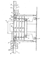
Diese zeigt einen Längsschnitt durch die Vorrichtung. Zwischen einem teilweise nur dargestellten Rütteltisch 1 sowie einem gleichfalls nur teilweise dargestellten Schneidetisch einer Papierschneidemaschine befindet sich -ein Stapellift 3. Dieser weist an seiner Unterseite Räder 4 zum Verfahren auf. Die teilweise angehobene Hubgabel 5 des Stapellifts 4 durchgreift eine Palette 6, auf der das Schneidegut unter Zwischenlage von Luftbrettern 7a bis 7e zu Teilstapeln 8a bis 8d gelagert wird.Further features of the invention are shown in the drawing of the figure.
This shows a longitudinal section through the device. Between a partly only shown vibrating table 1 and also a partly shown cutting table of a paper cutting machine there is a stack lift 3. This has wheels 4 for moving on its underside. The partially raised
An der Unterseite 9 der Arbeitsplatte 10 des Rütteltisches 1 sowie der Unterseite 11 der Arbeitsplatic 12 des Schneidetisches 2 sind senkrecht zur Zeichenebens mehrere Klappen 13 um die Gelenke 14 schwenkbar ![]()
![]()
![]()
![]()
Die Anordnung der Klappen an den Unterseiten 9 und 11 sowie die Abmessung der Klappen mit den am ![]()
![]()
![]()
![]()
Bei ausgefahrenen Klappen 13 ist die Hubgabel 5 des Stapelliftes 3 soweit nach unten verfahren, daß zwischen der Unterseite des Luftbrettes 7e und der Oberflache des Teilstapels 8d ein Zwischenraum verbleibt. Durch diesen ist gewährleistet, daß während des Verschiebens des Teilstapels 8e auf das Luftbrett 7e die oberen einzelnen Bogen des Teilstapels 8d nicht mit verschoben werden können.When the
Nachdem der Teilstapel 8e sich auf dem Luftbrett 7e befindet, wird die Hubgabel 5 des Stapelliftes 3 geringfügig angehoben , um die Klappen 13 zu entlasten. Im Gegensatz zu den Luftbrettern 7a bis 7d kommt dabei das Luftbrett 7e mit seinen vier Stützen 23 auf dem Luftbrett 7d zum Stehen, wobei es den auf dem Luftbrett 7d befindlichen Teilstapel 8d nicht berührt. Im Unterschied dazu weisen die übrigen Luftbretter 7a bis 7d derartige Stützen 23 nicht auf, das Brett 7b liegt direkt auf dem leilstapel 8a , das Brett 7c direkt auf dem Teilstapel 8b und das Brett 7d direkt auf dem Teilstapel 8c auf. Es ist jedoch gleichfalls möglich, alle Bretter mit oder ohne Stützen zu versehen.After the
Nachdem die Klappen 13 entlastet sind, werden sie über die hydraulischen Kraftglieder 15 zurückgeschwenkt. so daß sie sich außerhalb des beim Heben und Senken der Bretter 7a bis 7e gebildeten Hubraumes befinden (Außenkontur des Hubraumes strichliert dargestellt).After the
Das Einfügen weiterer Teilstapel in den Stapellift bzw. das Abarbeiten der Teilstapel aus dem Stapellift wurde bereits vorstehend erläutert.The insertion of further partial stacks into the stack lift or the processing of the partial stacks from the stack lift has already been explained above.
Claims (8)
dadurch gekennzeichnet, daß
unterhalb des Niveaus der Auflageflächen (20, 21) der Arbeitstische (10, 12) bewegliche Anschläge (13) angeordnet sind, wobei die Anschläge (13) sich in eingefahrener Position außerhalb des beim Heben-und Senken der Bretter (7a, 7b, 7c, 7d, 7e) gebildeten Hubraums befinden, in ausgefahrener Position in den Hubraum eingreifen und beim Auflegen eines Bretts (7e) auf die ausgefahrenen Anschläge (13) die Auflagefläche (19) des Brettes (7e) mit den Auflageflächen (20, 21) der Arbeitstische (10, -12) eine Ebene bildet.1. Device for intermediate stacking of material to be cut, in which the material to be cut is fed from the work table to a first work station, in particular a vibrating table, to a stack lift, on which the material to be cut is stored in part stacks with the interposition of boards and from there to the work table of a second work station, in particular a cutting table of a cutting machine,
characterized in that
Movable stops (13) are arranged below the level of the support surfaces (20, 21) of the work tables (10, 12), the stops (13) being in the retracted position outside of when the boards (7a, 7b, 7c are raised and lowered) , 7d, 7e) formed, engage in the extended position in the displacement and, when placing a board (7e) on the extended stops (13), the support surface (19) of the board (7e) with the support surfaces (20, 21) Work tables (10, -12) forms one level.
dadurch gekennzeichnet, daß die Anschläge als Klappen (13) ausgebildet sind, deren eines Ende an der Unterseite (9, 11) der Arbeitstische (10, 12) schwenkbar befestigt ist, und dessen freies Ende der Auflage des Brettes (7e) dient.2. Device according to claim 1,
characterized in that the stops are designed as flaps (13), one end of which is pivotally attached to the underside (9, 11) of the work tables (10, 12), and the free end of which supports the board (7e).
dadurch gekennzeichnet, daß an der Unterseite (9, 11) Arbeitstische (10, 12) Kraftelemente, insbesondere
characterized in that on the underside (9, 11) work tables (10, 12) force elements, in particular
über die Breite des Brettes (7e) mehrere Klappen (13) vorgesehen sind.4. The device according to one or more of claims 1 to 3, characterized in that
across the width of the board (7e) several flaps (13) are seen.
Priority Applications (1)
| Application Number | Priority Date | Filing Date | Title |
|---|---|---|---|
| AT84115166T ATE27439T1 (en) | 1983-12-14 | 1984-12-11 | DEVICE FOR INTERMEDIATE STACKING OF CUTS. |
Applications Claiming Priority (2)
| Application Number | Priority Date | Filing Date | Title |
|---|---|---|---|
| DE19838335816U DE8335816U1 (en) | 1983-12-14 | 1983-12-14 | DEVICE FOR INTERMEDIATE STACKING OF CUT PRODUCTS |
| DE8335816U | 1983-12-14 |
Publications (3)
| Publication Number | Publication Date |
|---|---|
| EP0146869A2 true EP0146869A2 (en) | 1985-07-03 |
| EP0146869A3 EP0146869A3 (en) | 1985-07-31 |
| EP0146869B1 EP0146869B1 (en) | 1987-05-27 |
Family
ID=6759824
Family Applications (1)
| Application Number | Title | Priority Date | Filing Date |
|---|---|---|---|
| EP84115166A Expired EP0146869B1 (en) | 1983-12-14 | 1984-12-11 | Intermediate stacking device for cutting goods |
Country Status (6)
| Country | Link |
|---|---|
| US (1) | US4613267A (en) |
| EP (1) | EP0146869B1 (en) |
| JP (2) | JPS60144276A (en) |
| AT (1) | ATE27439T1 (en) |
| DE (2) | DE8335816U1 (en) |
| ES (1) | ES8603785A1 (en) |
Cited By (2)
| Publication number | Priority date | Publication date | Assignee | Title |
|---|---|---|---|---|
| FR2587311A1 (en) * | 1985-09-18 | 1987-03-20 | Schauman | Method and installation for automatic handling and temporary storage of stacked packets of semi-finished sheet products |
| EP0652171A1 (en) * | 1993-10-05 | 1995-05-10 | SEEMI Société d'Etudes d'Equipements de Modernisation Industrielle | Method of and device for palletizing tubular sections made of paper or the like |
Families Citing this family (6)
| Publication number | Priority date | Publication date | Assignee | Title |
|---|---|---|---|---|
| DE3613462A1 (en) * | 1986-04-22 | 1987-10-29 | Wolfgang Mohr | Device for loading and unloading a stack lift |
| US5256028A (en) * | 1986-07-23 | 1993-10-26 | Winski Ernest P | Process for handling material |
| DE3914598C2 (en) * | 1989-05-03 | 1994-05-19 | Focke & Co | Method and device for removing objects from a surface with high frictional resistance |
| DE3940190A1 (en) * | 1989-12-05 | 1991-06-06 | Kolbus Gmbh & Co Kg | METHOD FOR LOADING AND UNLOADING PALLETS WITH STACKS OF FLAT PRODUCTS AND DEVICE FOR CARRYING OUT THE METHOD |
| US5562403A (en) * | 1991-02-11 | 1996-10-08 | Winski; Ernest P. | Load forming apparatus and methods |
| US6305500B1 (en) * | 1999-08-25 | 2001-10-23 | Maxtor Corporation | Material delivery system for clean room-like environments |
Citations (5)
| Publication number | Priority date | Publication date | Assignee | Title |
|---|---|---|---|---|
| DE1244711B (en) * | 1965-06-12 | 1967-07-20 | Rudolf Mohr | Device for stacking material to be cut and automatically feeding it to the workbench, in particular for paper cutting machines |
| US3548995A (en) * | 1968-06-13 | 1970-12-22 | Sta Hi Corp | Controlled variable speed stacking device for publication conveyor |
| DE2330569A1 (en) * | 1972-06-15 | 1974-01-03 | Harris Intertype Corp | DEVICE AND METHOD FOR CONTINUOUS TRANSFER AND STACKING OF SHEET MATERIAL, IN PARTICULAR OF SHEETS |
| CA975813A (en) * | 1974-09-06 | 1975-10-07 | Theodore E. O'brien | Apparatus for automatically stacking and compressing batts of compressible material |
| DE2427635A1 (en) * | 1974-06-07 | 1975-12-18 | Hobema Maschf Hermann | Folding machine supply attachment - fitted with sensor unit and locking link to separate pack from stack |
Family Cites Families (11)
| Publication number | Priority date | Publication date | Assignee | Title |
|---|---|---|---|---|
| US30742A (en) * | 1860-11-27 | Improvement in ordnance | ||
| US674262A (en) * | 1900-02-21 | 1901-05-14 | Garland H Duncan | Lumber-stacker. |
| US1225523A (en) * | 1915-02-27 | 1917-05-08 | Robert E Surles | Lumber-stacker. |
| US3146897A (en) * | 1962-01-11 | 1964-09-01 | Kalamazoo Paper Company | Paper pile separating and stacking transfer apparatus |
| US3363781A (en) * | 1963-06-14 | 1968-01-16 | Magnetti Enrico | Stacking mechanism |
| US3398841A (en) * | 1967-02-07 | 1968-08-27 | Mohr Rudolf | Apparatus for stacking material and automatically feeding the material to a worktable of a paper-cutting machine |
| US3897877A (en) * | 1973-08-22 | 1975-08-05 | Goldco Industries | Apparatus for positioning and orienting palletized articles |
| JPS5655166U (en) * | 1979-10-06 | 1981-05-14 | ||
| JPS6011676B2 (en) * | 1980-04-10 | 1985-03-27 | 小森印刷機械株式会社 | Paper flow prevention device in printing machine paper output section |
| JPS5930620B2 (en) * | 1981-05-21 | 1984-07-27 | 東洋ガラス機械株式会社 | Container removal and transfer device from multi-layered containers |
| JPS5811787U (en) * | 1981-07-15 | 1983-01-25 | 株式会社日立製作所 | destination display device |
-
1983
- 1983-12-14 DE DE19838335816U patent/DE8335816U1/en not_active Expired
-
1984
- 1984-12-07 JP JP59257741A patent/JPS60144276A/en active Pending
- 1984-12-10 US US06/679,745 patent/US4613267A/en not_active Expired - Fee Related
- 1984-12-11 DE DE8484115166T patent/DE3463921D1/en not_active Expired
- 1984-12-11 EP EP84115166A patent/EP0146869B1/en not_active Expired
- 1984-12-11 AT AT84115166T patent/ATE27439T1/en not_active IP Right Cessation
- 1984-12-14 ES ES538622A patent/ES8603785A1/en not_active Expired
-
1991
- 1991-09-27 JP JP1991099454U patent/JP2525234Y2/en not_active Expired - Lifetime
Patent Citations (5)
| Publication number | Priority date | Publication date | Assignee | Title |
|---|---|---|---|---|
| DE1244711B (en) * | 1965-06-12 | 1967-07-20 | Rudolf Mohr | Device for stacking material to be cut and automatically feeding it to the workbench, in particular for paper cutting machines |
| US3548995A (en) * | 1968-06-13 | 1970-12-22 | Sta Hi Corp | Controlled variable speed stacking device for publication conveyor |
| DE2330569A1 (en) * | 1972-06-15 | 1974-01-03 | Harris Intertype Corp | DEVICE AND METHOD FOR CONTINUOUS TRANSFER AND STACKING OF SHEET MATERIAL, IN PARTICULAR OF SHEETS |
| DE2427635A1 (en) * | 1974-06-07 | 1975-12-18 | Hobema Maschf Hermann | Folding machine supply attachment - fitted with sensor unit and locking link to separate pack from stack |
| CA975813A (en) * | 1974-09-06 | 1975-10-07 | Theodore E. O'brien | Apparatus for automatically stacking and compressing batts of compressible material |
Cited By (2)
| Publication number | Priority date | Publication date | Assignee | Title |
|---|---|---|---|---|
| FR2587311A1 (en) * | 1985-09-18 | 1987-03-20 | Schauman | Method and installation for automatic handling and temporary storage of stacked packets of semi-finished sheet products |
| EP0652171A1 (en) * | 1993-10-05 | 1995-05-10 | SEEMI Société d'Etudes d'Equipements de Modernisation Industrielle | Method of and device for palletizing tubular sections made of paper or the like |
Also Published As
| Publication number | Publication date |
|---|---|
| JP2525234Y2 (en) | 1997-02-05 |
| JPH081281U (en) | 1996-08-13 |
| EP0146869B1 (en) | 1987-05-27 |
| DE8335816U1 (en) | 1984-04-26 |
| EP0146869A3 (en) | 1985-07-31 |
| US4613267A (en) | 1986-09-23 |
| JPS60144276A (en) | 1985-07-30 |
| DE3463921D1 (en) | 1987-07-02 |
| ES8603785A1 (en) | 1986-01-16 |
| ES538622A0 (en) | 1986-01-16 |
| ATE27439T1 (en) | 1987-06-15 |
Similar Documents
| Publication | Publication Date | Title |
|---|---|---|
| EP0077508B1 (en) | Method and device for packaging goods stacked on a pallet | |
| DE2440278C2 (en) | Device for palletizing objects | |
| DE7908192U1 (en) | STACKING DEVICE | |
| DE10392503T5 (en) | palette | |
| DE10123326C1 (en) | Delivery device, for a machine processing sheets of paper, has a transport unit for transporting sheets from one position to a further position | |
| DE2952624A1 (en) | DEVICE FOR GROUPING OBJECTS IN STACKED LAYERS FOR LOADING PALLETS | |
| DE2547149A1 (en) | METHOD AND DEVICE FOR MANUFACTURING PLATES OR PANELS FROM PULP, OR. FIBER OR CHARPING MATERIAL | |
| EP0146869B1 (en) | Intermediate stacking device for cutting goods | |
| EP0316568A2 (en) | Apparatus for removing stacks of sheets | |
| DE2942965A1 (en) | Stacking control for printer - has insert plate with air cushion to hold stack when magazine is changed | |
| DE202017004863U1 (en) | Plant for storing and transporting pallets | |
| EP0132635A2 (en) | Loading device for elongate objects | |
| DE4021676C1 (en) | ||
| DE19708125A1 (en) | Forklift | |
| DE3820236A1 (en) | INPUT DEVICE OF PACKAGES FORMED FROM PLATE STACKS AND METHOD FOR PROVIDING THE PACKAGES ON THE INPUT DEVICE | |
| DE3105237A1 (en) | System for improving chipboards, fibre boards and the like | |
| DE19831640A1 (en) | Collapsible container for the delivery of motor vehicle body panels | |
| DE2626630C2 (en) | Method and device for separating and stacking punched sheets | |
| EP0298435B1 (en) | Device for transporting cardboard blanks | |
| EP0191807B1 (en) | Process and system for pallet changing | |
| DE3914598C2 (en) | Method and device for removing objects from a surface with high frictional resistance | |
| EP0945370B1 (en) | Positioning device for at least one pallet | |
| DE2630094A1 (en) | Card stacking and separating process - in which stamped cards are stacked on separating table during pallet exchanges | |
| DE1506511A1 (en) | Device and method for transporting panels | |
| DE2900375A1 (en) | DEVICE FOR SEPARATING SHEETS OF PAPER O.AE. |
Legal Events
| Date | Code | Title | Description |
|---|---|---|---|
| PUAI | Public reference made under article 153(3) epc to a published international application that has entered the european phase |
Free format text: ORIGINAL CODE: 0009012 |
|
| PUAL | Search report despatched |
Free format text: ORIGINAL CODE: 0009013 |
|
| 17P | Request for examination filed |
Effective date: 19841224 |
|
| AK | Designated contracting states |
Designated state(s): AT BE CH DE FR GB IT LI LU NL SE |
|
| ITCL | It: translation for ep claims filed |
Representative=s name: MODIANO & ASSOCIATI S.R.L. |
|
| AK | Designated contracting states |
Designated state(s): AT BE CH DE FR GB IT LI LU NL SE |
|
| EL | Fr: translation of claims filed | ||
| TCNL | Nl: translation of patent claims filed | ||
| 17Q | First examination report despatched |
Effective date: 19860221 |
|
| GRAA | (expected) grant |
Free format text: ORIGINAL CODE: 0009210 |
|
| AK | Designated contracting states |
Kind code of ref document: B1 Designated state(s): AT BE CH DE FR GB IT LI LU NL SE |
|
| REF | Corresponds to: |
Ref document number: 27439 Country of ref document: AT Date of ref document: 19870615 Kind code of ref document: T |
|
| REF | Corresponds to: |
Ref document number: 3463921 Country of ref document: DE Date of ref document: 19870702 |
|
| ET | Fr: translation filed | ||
| ITF | It: translation for a ep patent filed |
Owner name: MODIANO & ASSOCIATI S.R.L. |
|
| PLBE | No opposition filed within time limit |
Free format text: ORIGINAL CODE: 0009261 |
|
| STAA | Information on the status of an ep patent application or granted ep patent |
Free format text: STATUS: NO OPPOSITION FILED WITHIN TIME LIMIT |
|
| 26N | No opposition filed | ||
| REG | Reference to a national code |
Ref country code: CH Ref legal event code: PUE Owner name: ROLF MOHR |
|
| NLS | Nl: assignments of ep-patents |
Owner name: ROLF MOHR EN WOLFGANG MOHR BEIDEN TE HOFHEIM A.D. |
|
| REG | Reference to a national code |
Ref country code: FR Ref legal event code: TP |
|
| ITPR | It: changes in ownership of a european patent |
Owner name: CESSIONE;ROLF MOHR |
|
| REG | Reference to a national code |
Ref country code: GB Ref legal event code: 732 |
|
| ITTA | It: last paid annual fee | ||
| EPTA | Lu: last paid annual fee | ||
| EAL | Se: european patent in force in sweden |
Ref document number: 84115166.5 |
|
| PGFP | Annual fee paid to national office [announced via postgrant information from national office to epo] |
Ref country code: LU Payment date: 19961101 Year of fee payment: 13 |
|
| PGFP | Annual fee paid to national office [announced via postgrant information from national office to epo] |
Ref country code: SE Payment date: 19961125 Year of fee payment: 13 Ref country code: CH Payment date: 19961125 Year of fee payment: 13 |
|
| PGFP | Annual fee paid to national office [announced via postgrant information from national office to epo] |
Ref country code: GB Payment date: 19961126 Year of fee payment: 13 Ref country code: BE Payment date: 19961126 Year of fee payment: 13 |
|
| PGFP | Annual fee paid to national office [announced via postgrant information from national office to epo] |
Ref country code: NL Payment date: 19961127 Year of fee payment: 13 |
|
| PGFP | Annual fee paid to national office [announced via postgrant information from national office to epo] |
Ref country code: FR Payment date: 19961128 Year of fee payment: 13 Ref country code: AT Payment date: 19961128 Year of fee payment: 13 |
|
| PGFP | Annual fee paid to national office [announced via postgrant information from national office to epo] |
Ref country code: DE Payment date: 19961227 Year of fee payment: 13 |
|
| PG25 | Lapsed in a contracting state [announced via postgrant information from national office to epo] |
Ref country code: LU Free format text: LAPSE BECAUSE OF NON-PAYMENT OF DUE FEES Effective date: 19971211 Ref country code: GB Free format text: LAPSE BECAUSE OF NON-PAYMENT OF DUE FEES Effective date: 19971211 Ref country code: AT Free format text: LAPSE BECAUSE OF NON-PAYMENT OF DUE FEES Effective date: 19971211 |
|
| PG25 | Lapsed in a contracting state [announced via postgrant information from national office to epo] |
Ref country code: SE Free format text: LAPSE BECAUSE OF NON-PAYMENT OF DUE FEES Effective date: 19971212 |
|
| PG25 | Lapsed in a contracting state [announced via postgrant information from national office to epo] |
Ref country code: LI Free format text: LAPSE BECAUSE OF NON-PAYMENT OF DUE FEES Effective date: 19971231 Ref country code: FR Free format text: THE PATENT HAS BEEN ANNULLED BY A DECISION OF A NATIONAL AUTHORITY Effective date: 19971231 Ref country code: CH Free format text: LAPSE BECAUSE OF NON-PAYMENT OF DUE FEES Effective date: 19971231 Ref country code: BE Free format text: LAPSE BECAUSE OF NON-PAYMENT OF DUE FEES Effective date: 19971231 |
|
| BERE | Be: lapsed |
Owner name: MOHR ROLF Effective date: 19971231 Owner name: MOHR WOLFGANG Effective date: 19971231 |
|
| PG25 | Lapsed in a contracting state [announced via postgrant information from national office to epo] |
Ref country code: NL Free format text: LAPSE BECAUSE OF NON-PAYMENT OF DUE FEES Effective date: 19980701 |
|
| GBPC | Gb: european patent ceased through non-payment of renewal fee |
Effective date: 19971211 |
|
| REG | Reference to a national code |
Ref country code: CH Ref legal event code: PL |
|
| NLV4 | Nl: lapsed or anulled due to non-payment of the annual fee |
Effective date: 19980701 |
|
| PG25 | Lapsed in a contracting state [announced via postgrant information from national office to epo] |
Ref country code: DE Free format text: LAPSE BECAUSE OF NON-PAYMENT OF DUE FEES Effective date: 19980901 |
|
| EUG | Se: european patent has lapsed |
Ref document number: 84115166.5 |
|
| REG | Reference to a national code |
Ref country code: FR Ref legal event code: ST |