EP0146867A2 - Optischer Dämpfungsregler für Kupplung von optischen Fasern - Google Patents
Optischer Dämpfungsregler für Kupplung von optischen Fasern Download PDFInfo
- Publication number
- EP0146867A2 EP0146867A2 EP84115148A EP84115148A EP0146867A2 EP 0146867 A2 EP0146867 A2 EP 0146867A2 EP 84115148 A EP84115148 A EP 84115148A EP 84115148 A EP84115148 A EP 84115148A EP 0146867 A2 EP0146867 A2 EP 0146867A2
- Authority
- EP
- European Patent Office
- Prior art keywords
- fibers
- support
- branch
- face
- optical attenuator
- Prior art date
- Legal status (The legal status is an assumption and is not a legal conclusion. Google has not performed a legal analysis and makes no representation as to the accuracy of the status listed.)
- Granted
Links
Images

Classifications
-
- G—PHYSICS
- G02—OPTICS
- G02B—OPTICAL ELEMENTS, SYSTEMS OR APPARATUS
- G02B6/00—Light guides; Structural details of arrangements comprising light guides and other optical elements, e.g. couplings
- G02B6/24—Coupling light guides
- G02B6/26—Optical coupling means
- G02B6/35—Optical coupling means having switching means
- G02B6/3564—Mechanical details of the actuation mechanism associated with the moving element or mounting mechanism details
- G02B6/3568—Mechanical details of the actuation mechanism associated with the moving element or mounting mechanism details characterised by the actuating force
- G02B6/3574—Mechanical force, e.g. pressure variations
-
- G—PHYSICS
- G02—OPTICS
- G02B—OPTICAL ELEMENTS, SYSTEMS OR APPARATUS
- G02B6/00—Light guides; Structural details of arrangements comprising light guides and other optical elements, e.g. couplings
- G02B6/24—Coupling light guides
- G02B6/26—Optical coupling means
- G02B6/264—Optical coupling means with optical elements between opposed fibre ends which perform a function other than beam splitting
- G02B6/266—Optical coupling means with optical elements between opposed fibre ends which perform a function other than beam splitting the optical element being an attenuator
-
- G—PHYSICS
- G02—OPTICS
- G02B—OPTICAL ELEMENTS, SYSTEMS OR APPARATUS
- G02B6/00—Light guides; Structural details of arrangements comprising light guides and other optical elements, e.g. couplings
- G02B6/24—Coupling light guides
- G02B6/26—Optical coupling means
- G02B6/35—Optical coupling means having switching means
- G02B6/354—Switching arrangements, i.e. number of input/output ports and interconnection types
- G02B6/3544—2D constellations, i.e. with switching elements and switched beams located in a plane
- G02B6/3548—1xN switch, i.e. one input and a selectable single output of N possible outputs
- G02B6/3552—1x1 switch, e.g. on/off switch
-
- G—PHYSICS
- G02—OPTICS
- G02B—OPTICAL ELEMENTS, SYSTEMS OR APPARATUS
- G02B6/00—Light guides; Structural details of arrangements comprising light guides and other optical elements, e.g. couplings
- G02B6/24—Coupling light guides
- G02B6/26—Optical coupling means
- G02B6/35—Optical coupling means having switching means
- G02B6/3594—Characterised by additional functional means, e.g. means for variably attenuating or branching or means for switching differently polarized beams
Definitions
- the present invention is in the field of broadband transmissions by unimodal optical fibers. It relates more particularly to a variable optical attenuator allowing precise measurements of the error rate of such transmission systems and a fine-tuning of the devices returning to these systems. This optical attenuator must therefore be precise, compact, simple and inexpensive.
- unimodal fibers in high speed transmission systems encourages the use of unimodal fiber optic attenuators, in which the attenuation function is obtained by varying the coupling parameters of a fiber to fiber junction, which are the angle of inclination between the ends of the two fibers and their distance or the two orthogonal components which define this distance.
- variable optical attenuator for use in single-mode fiber transmission systems
- the basic idea retained for the realization of a variable optical attenuator then consists in making mobile on an arc of a circle the end of one of the fibers of a weakening element which defines the fiber to fiber junction of this attenuator.
- the weakening element comprises a support with a concave V-groove, extending in an arc of a circle, which receives the two ends of the two unimodal fibers defining the junction.
- the end of one of the fibers is fixed in the groove.
- the end of the other fiber is made mobile along the groove.
- this other fiber is integral with one of the ends of an arm mounted to pivot, at its other end, around the center of the circle defined by the V-groove and controlled from a precision micrometric head giving the amplitude of its displacement.
- the two fibers are necessarily mounted in V-shaped grooves, for reasons of precision, and of reproducibility of the attenuation values provided as a function of groups of values taken individually by these parameters.
- the range of possible attenuation values as well as the precision and the reproducibility of these attenuation values are therefore limited by the very fact of this relative mode of holding the fibers, and also by the parasitic reflections on the walls of the groove when the distance between the ends of the fibers increases.
- the precision and reproducibility of the attenuation values which are linked to the precision of the machining of the groove are also directly dependent on the conditions of use and handling of the attenuator which can lead to damage to the end of the movable fiber in the groove and under the effect of shocks or vibrations applied or transmitted to the attenuator, at the partial or total exit from the groove of the movable fiber in particular which is held against the bottom of the groove simply under the effect of its bending.
- the object of the present invention is to define a structure of simple variable optical attenuator and of easy industrial manufacture, in particular avoiding these drawbacks.
- variable optical attenuator comprising a weakening element providing variable coupling between the first ends of two optical fibers carried by a support by displacement of the first end of one of the fibers on an arc passing through the first end of the other fiber, characterized in that said fibers are both mounted fixed on said support and that said support is of rectangular shape, receives on one of its large faces, said retaining face, said fibers and has, on the one hand, a slit, parallel to its large faces, which extends over part of its length defining therein a first branch to which the said retaining face belongs and a second branch to which the large opposite face belongs , and, on the other hand, a cylindrical hole made transversely in said first branch, substantially at the bottom of said slot and open on said retaining face by defining there the coupling zone between said fibers, and by the fact that it further comprises means for actuating in rotation said first branch displaceable in rotation by elastic deformation of said cylindrical hole, acting substantially at the level of the free end of this first branch.
- control means comprise a threaded rod of which one end is retained, while being free to rotate, in the free end of said first branch and a non-deformable strip on the one hand crossed by said rod and on the other hand made integral with said support, only over the part of its length not divided by said slot.
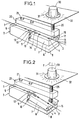
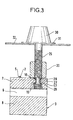
- FIGS. 1 and 2 an embodiment of the optical attenuator according to the invention is illustrated, or more precisely the weakening element which this attenuator comprises and which ensures variable coupling between the first ends of two unimodal fibers 1 and 2.
- This weakening element is of the weakening function type made variable by displacement of the first end of one of the fibers on an arc of a circle on which the first end of the other fiber is fixed.
- the two fibers 1 and 2 will have their respective second ends coupled to line fibers exterior not shown.
- the weakening element of the variable attenuator has a support 3 for. the two fibers 1 and 2.
- This support 3 is of parallelepiped shape; the two fibers 1 and 2 are aligned with each other on one of the large flat faces of the support, called the fiber holding face 4 and fixed on this large face of the support by bonding points such as 5 after precise adjustment of the relative positioning of their respective first coupling ends, carried out using a binocular device and a precision gripper manipulator.
- the support 3 of the fibers has a slot 6 parallel to its large faces and extending over a first part of its length, substantially here a first half.
- the slot 6 divides this first part of the support into two branches 7 and 8. It further comprises a cylindrical hole 9 formed in the branch 7 to which the holding face 4 of the fibers belongs, substantially at the bottom of the slot 6, being parallel to the bottom of this slot.
- the cylindrical hole 9 passes through the support 3 right through.
- This hole 9 remains separated from the slot 6 by a thin partition which it maintains over its length opposite it in the branch 7 and the part of which is thinner referenced 10 is called hinge below. It is, on the other hand, substantially opposite the hinge 10, open along its length on the face 4 for holding the fibers through a narrow opening window 12 transverse to the face 4.
- the first coupling ends of the two fibers 1 and 2 are free of bonding points, they are positioned just above this window 12.
- the support 3 further comprises two blind holes 13 and 14, made through the holding face 4 of the fibers, on either side of the window 12 and on the positioning paths of the fibers. These holes, which are large relative to the diameter of the fibers which extend over their surface, help to facilitate the adjustment of the relative positions of the first ends of the fibers, by allowing an all-round deflection of the ends of the grippers for gripping the fibers of the precision manipulator. cited above.
- the support 3 will preferably be chosen from a brass-based material which is easy to machine and which has a modulus of elasticity of the order of 50 da N / mm 2 ; it will advantageously be made of a material known under the name "NiCladec 3444" marketed by "Le Comptoir Lyon Alemand Louyot”.
- the weakening element further comprises a rigid strip 20 and a control rod 25 associated with each other and with the support 3, for controlling the resulting weakening element.
- the rigid strip 20 is a solid strip, non-deformable. It is applied to the holding face 4 of the fibers and is made integral with the support 3 by screws 21 only on the second half of this support 3, that is to say on the part of the support not divided by the slot 6 , the branch 7 and the strip 20 therefore being not directly fixed to each other.
- This strip 20 extends over the entire length of the face 4 but simply occupies on this face only substantially half the width of this face, the other half being intended for holding the two fibers.
- This strip 20 has, in its part not fixed to the support 3 and in the vicinity of its end, a threaded hole with fine pitch, not referenced, for receiving the control rod 25 which is threaded in correspondence.
- this threaded rod 25 screwed into the strip it crosses has its end held captive, while remaining free in rotation, in the end of branch 7 defined in support 3.
- the end of this rod engaged in the branch 7 has, for this purpose, a groove 27 and two conical shoulders 29 and 28 connecting the groove with the threaded end part and the other adjacent threaded part, giving it a form of diabolo.
- the end of the branch 7 has, in correspondence, an opening 15 formed in its thickness for housing the end of the rod 25. This opening opens at the end of the branch 7, for the insertion of the rod. It is profiled to ensure the retention of the diabolo-shaped end of the rod in the branch while allowing its free rotation, by a rib 17 with inclined edges 18 and 19, which have the edges limiting its outline in the thickness of the branch. This rib 17 is received in the groove 27, the inclined edges 18 and 19 of this rib are applied against the conical shoulders 28 and 29 of the rod 25.
- the opposite end of the rod 25 carries an operating button 30 with indexing flange 31 movable on a plate 32 graduated on the periphery of the flange.
- the coupling between the fibers is made variable by simple actuation in rotation of the operating button 30, according to arrow F in FIG. 2 from the initial position given in FIG. 1.
- This rotation causes the advance, through the slide 20, of the rod 25 which comes to push on the free end of the branch 7, which causes the rotation, according to the arrow d of FIG. 2, of the branch 7 around of the hinge 10 by elastic deformation of the cylindrical hole 9.
- the first end of the fiber 2, carried by this branch 7, thus moves on an arc centered on the hinge 10 in front of the first end of the other fiber 1.
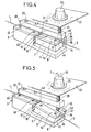
- FIGS. 4, 5 and 6 a variant of realization of the previous optical attenuator.
- the elements identical to those of FIGS. 1 to 3 are designated under the same references and are not described again below.
- the fibers 1 and 2 are positioned at the bottom of a V-groove 40 visible more particularly in FIG. 6, which is defined between the face 4 of the support 3 and the side face of a positioning bar 41, narrower than the support 3, which partially covers the face 4 of the support and is fixed to the support.
- the coupling between these two fibers is also located at the opening window 12 in the support and a slot 42, preferably after machining with the window 12 with which it is aligned, which divides the strip 41 into two dependent parts, one of the branch 7 and the other of the part of the support not divided by the slot 6.
- the fibers 1 and 2 are kept applied to the bottom of their V-groove by two holding plates 43 and 44 having each for this purpose a chamfered edge 45. These plates are substantially the same thickness as the positioning bar. They are attached to the bar 41 and extend on the face 4 of the support 3 on either side of the window 12. They are fixed by screws 46 and 47 to the support 3.
- the positioning bar 41 secured to the support 3 and divided into two parts is therefore simply interposed between the support 3 and the strip 20. It projects under the strip for the accessibility of the V-groove which it defines with support. Its end, on the side of the end of the branch 7 receiving the diabolo end of the rod 25, has a wide notch 48 for the free passage of this rod.
- FIG 7 there is illustrated the optical attenuator according to the invention mounted in a housing 50 closed by a cover 51.
- the fibers 1 and 2 pass through the opposite side walls of this housing through seals 52, 53, sealed.
- the rod 25 passes through the cover 51 through a another etano seal not shown, the operating button 30 being just above this cover.
- the closed housing 50, 51 is preferably filled with a liquid 55, such as that known under the name Opanol or Eucalyptol, with a refractive index approximately equal to that of the core of the fibers, forming an interface junction between the two fibers 1 and 2 to improve their coupling.
- a liquid 55 such as that known under the name Opanol or Eucalyptol
Landscapes
- Physics & Mathematics (AREA)
- General Physics & Mathematics (AREA)
- Optics & Photonics (AREA)
- Optical Couplings Of Light Guides (AREA)
- Mechanical Coupling Of Light Guides (AREA)
Applications Claiming Priority (2)
| Application Number | Priority Date | Filing Date | Title |
|---|---|---|---|
| FR8320214 | 1983-12-16 | ||
| FR8320214A FR2556849B1 (fr) | 1983-12-16 | 1983-12-16 | Attenuateur optique variable pour couplage de fibres optiques |
Publications (3)
| Publication Number | Publication Date |
|---|---|
| EP0146867A2 true EP0146867A2 (de) | 1985-07-03 |
| EP0146867A3 EP0146867A3 (en) | 1985-08-14 |
| EP0146867B1 EP0146867B1 (de) | 1989-07-26 |
Family
ID=9295268
Family Applications (1)
| Application Number | Title | Priority Date | Filing Date |
|---|---|---|---|
| EP84115148A Expired EP0146867B1 (de) | 1983-12-16 | 1984-12-13 | Optischer Dämpfungsregler für Kupplung von optischen Fasern |
Country Status (6)
| Country | Link |
|---|---|
| US (1) | US4645294A (de) |
| EP (1) | EP0146867B1 (de) |
| JP (1) | JPS60151605A (de) |
| CA (1) | CA1251969A (de) |
| DE (1) | DE3479161D1 (de) |
| FR (1) | FR2556849B1 (de) |
Cited By (1)
| Publication number | Priority date | Publication date | Assignee | Title |
|---|---|---|---|---|
| EP1250615A4 (de) * | 1999-12-30 | 2005-04-27 | Corning Inc | Thermisch kompensiertes varibles optisches dämpfungsglied mit verschiebemechanismus |
Families Citing this family (21)
| Publication number | Priority date | Publication date | Assignee | Title |
|---|---|---|---|---|
| US4989938A (en) * | 1988-09-08 | 1991-02-05 | Light Control Systems, Inc. | Continuously variable fiber optic attenuator |
| US4904044A (en) * | 1988-09-08 | 1990-02-27 | Light Control Systems, Inc. | Continuously variable fiber optic attenuator |
| US5109468A (en) * | 1990-05-08 | 1992-04-28 | M/A-Com Light Control Systems, Inc. | Fixed value fiber optic attenuator |
| US5050956A (en) * | 1990-09-20 | 1991-09-24 | Hunter Associates Laboratory Inc. | Optical fiber attenuator and connecting element |
| DE69232082T2 (de) * | 1991-11-18 | 2002-03-07 | Nippon Telegraph And Telephone Corp., Tokio/Tokyo | Einrichtung zum Zusammenstecken von optischen Steckverbindern |
| US5319733A (en) * | 1992-01-02 | 1994-06-07 | Adc Telecommunications, Inc. | Variable fiber optical attenuator |
| AU671599B2 (en) * | 1992-01-02 | 1996-09-05 | Adc Telecommunications, Incorporated | Overlapping fusion attenuator |
| US5311614A (en) * | 1992-03-31 | 1994-05-10 | The Whitaker Corporation | Single mode fiber optic variable attenuator with supported optical fiber |
| US5392146A (en) * | 1993-01-25 | 1995-02-21 | Motorola, Inc. | Optical rotary control device |
| WO1996001014A1 (en) * | 1994-06-29 | 1996-01-11 | Motorola Inc. | Optical rotary control device using a microprocessor |
| US5781341A (en) * | 1995-06-30 | 1998-07-14 | Dicon Fiberoptics, Inc. | Motorized tunable filter and motorized variable attenuator |
| US5727099A (en) * | 1996-07-19 | 1998-03-10 | Harman; Murray R. | Positioning system for controlling optical alignment of optical waveguides |
| US5841915A (en) * | 1996-11-04 | 1998-11-24 | Honeywell Inc. | Apparatus for determining the effect of modal noise on a communication system by affecting an optical fiber discontinuity |
| US6085016A (en) * | 1998-06-15 | 2000-07-04 | Lucent Technologies, Inc. | Magnetically controlled variable optical attenuator |
| US6243528B1 (en) * | 1998-09-25 | 2001-06-05 | Agere Systems Optoelectronics Guardian Corp. | Fiber locking system |
| US6625378B2 (en) | 1999-02-01 | 2003-09-23 | Jds Uniphase Corporation | Variable optical attenuator device |
| US6363203B1 (en) * | 1999-09-16 | 2002-03-26 | Agere Systems Guardian Corp. | Variable fiber optic attenuator |
| US6807331B2 (en) * | 2000-09-19 | 2004-10-19 | Newport Opticom, Inc. | Structures that correct for thermal distortion in an optical device formed of thermally dissimilar materials |
| CA2436392C (en) * | 2002-08-05 | 2011-02-01 | Luminos Industries Ltd. | Moving fiber optical switch |
| US6980727B1 (en) * | 2004-12-13 | 2005-12-27 | Xerox Corporation | Methodology for a MEMS variable optical attenuator |
| US7298954B2 (en) * | 2005-06-16 | 2007-11-20 | Xerox Corporation | Waveguide shuttle MEMS variable optical attenuator |
Family Cites Families (7)
| Publication number | Priority date | Publication date | Assignee | Title |
|---|---|---|---|---|
| JPS52115230A (en) * | 1976-03-24 | 1977-09-27 | Nippon Telegr & Teleph Corp <Ntt> | Optical fiber connector |
| US4196032A (en) * | 1978-03-22 | 1980-04-01 | Essex Group, Inc. | Splice for optical ribbon having elongated strain relief elements in the ribbon and method of splicing the same |
| JPS5678803A (en) * | 1979-11-30 | 1981-06-29 | Fujitsu Ltd | Light attenuator |
| JPS56156812A (en) * | 1980-05-09 | 1981-12-03 | Nippon Telegr & Teleph Corp <Ntt> | Aligning device for optical fiber |
| JPS575601U (de) * | 1980-06-12 | 1982-01-12 | ||
| JPS6024443B2 (ja) * | 1981-02-03 | 1985-06-13 | 日本電信電話株式会社 | 光フアイバ心線のコア軸合せ装置 |
| JPS59111120A (ja) * | 1982-12-15 | 1984-06-27 | Furukawa Electric Co Ltd:The | 光フアイバ用軸合装置 |
-
1983
- 1983-12-16 FR FR8320214A patent/FR2556849B1/fr not_active Expired
-
1984
- 1984-12-11 US US06/680,446 patent/US4645294A/en not_active Expired - Fee Related
- 1984-12-12 JP JP59262642A patent/JPS60151605A/ja active Pending
- 1984-12-13 CA CA000470080A patent/CA1251969A/fr not_active Expired
- 1984-12-13 DE DE8484115148T patent/DE3479161D1/de not_active Expired
- 1984-12-13 EP EP84115148A patent/EP0146867B1/de not_active Expired
Cited By (1)
| Publication number | Priority date | Publication date | Assignee | Title |
|---|---|---|---|---|
| EP1250615A4 (de) * | 1999-12-30 | 2005-04-27 | Corning Inc | Thermisch kompensiertes varibles optisches dämpfungsglied mit verschiebemechanismus |
Also Published As
| Publication number | Publication date |
|---|---|
| DE3479161D1 (en) | 1989-08-31 |
| EP0146867A3 (en) | 1985-08-14 |
| US4645294A (en) | 1987-02-24 |
| EP0146867B1 (de) | 1989-07-26 |
| JPS60151605A (ja) | 1985-08-09 |
| FR2556849A1 (fr) | 1985-06-21 |
| CA1251969A (fr) | 1989-04-04 |
| FR2556849B1 (fr) | 1986-03-28 |
Similar Documents
| Publication | Publication Date | Title |
|---|---|---|
| EP0146867B1 (de) | Optischer Dämpfungsregler für Kupplung von optischen Fasern | |
| EP0097575B1 (de) | Stecker für faseroptisches Verbindungsstück und Verbindungsstück mit solchem Stecker | |
| EP0107989B1 (de) | Vorrichtung zum Montieren optischer Fasern in einer Zwinge | |
| CA1131952A (fr) | Connecteur pour liaison a fibre optique | |
| CA1115102A (fr) | Attenuateur optique fixe pour rayonnements lumineux guides par fibre optique | |
| EP0481876B1 (de) | Justierverfahren der optischen Achsen von einer Faser und von einem optoelektronischen Bauelement und die mit diesem Verfahren hergestellte Vorrichtung | |
| EP0441676B1 (de) | Stecker für optische Fasern | |
| EP0115765B1 (de) | Drehschalter für optische Wellenführungsschaltung | |
| EP0682277B1 (de) | Anordnung zur Verbindung von optischen Fasern und Wellenleitern, die auf einem Substrat angebracht sind | |
| EP0176154B1 (de) | Verfahren zur Herstellung von einem Endbestandteil für eine optische Faser und Bestandteil so erhältlich | |
| FR2834565A1 (fr) | Dispositif pour faire entrer des signaux optiques dans un guide d'ondes de lumiere et/ou pour les en faire sortir | |
| EP0018873B1 (de) | Kompakte optische Koppelungsvorrichtung und solch eine Vorrichtung enthaltender interferometrischer Gyrometer mit einer optischen Faser | |
| EP0045271A1 (de) | Verbindung für optische Fasern | |
| EP0234981B1 (de) | T-förmige, optische Kupplung für Anwendungen in optischen Busnetzwerken und optischer Bus, versehen mit einer Vielzahl solcher Kupplungen | |
| EP0011012B1 (de) | Zentriervorrichtung für eine optische Faser in einer Zwinge und Zwinge mit einer optischem Faser die mit dieser Vorrichtung zentriert worden ist | |
| EP0176397B1 (de) | Vorrichtung zum Orientieren eines optischen Elementes | |
| EP0855721B1 (de) | Faseroptisches Kabel | |
| EP0096608A1 (de) | Faseroptischer Kollimator, Anwendung zur Realisierung optischer Schaltervorrichtungen | |
| EP0100124A1 (de) | Optisches Abbildungssystem für einen Zielsuchkopf | |
| EP0444566B1 (de) | Schneidezange mit kleiner Sperre zum Schneiden von optischen Fasern | |
| EP0098190B1 (de) | Vorrichtung zum Verbinden und zum Ausrichten zweier faseroptischen Verbindungsstecker mit einem V-förmigen Querschnitt | |
| EP0768548A1 (de) | Gerät zum Erleichtern der Herstellung optischer Faserverbindungen | |
| CA1299409C (fr) | Dispositif d'immobilisation rapide d'un element tubulaire dans un boitier d'appareillage et bloc de jonction pour fibres optiques dote d'untel dispositif | |
| EP0462881B1 (de) | Wand zur Abtrennung zweier Bereiche mit einer Vorrichtung zur Verbindung von zwei optischen Fasern | |
| EP0004811A2 (de) | Diaskop für eine Fernsehkamera |
Legal Events
| Date | Code | Title | Description |
|---|---|---|---|
| PUAI | Public reference made under article 153(3) epc to a published international application that has entered the european phase |
Free format text: ORIGINAL CODE: 0009012 |
|
| PUAL | Search report despatched |
Free format text: ORIGINAL CODE: 0009013 |
|
| AK | Designated contracting states |
Designated state(s): CH DE FR GB IT LI NL SE |
|
| AK | Designated contracting states |
Designated state(s): CH DE FR GB IT LI NL SE |
|
| 17P | Request for examination filed |
Effective date: 19860123 |
|
| 17Q | First examination report despatched |
Effective date: 19870126 |
|
| GRAA | (expected) grant |
Free format text: ORIGINAL CODE: 0009210 |
|
| AK | Designated contracting states |
Kind code of ref document: B1 Designated state(s): CH DE FR GB IT LI NL SE |
|
| REF | Corresponds to: |
Ref document number: 3479161 Country of ref document: DE Date of ref document: 19890831 |
|
| ITF | It: translation for a ep patent filed | ||
| GBT | Gb: translation of ep patent filed (gb section 77(6)(a)/1977) | ||
| PLBE | No opposition filed within time limit |
Free format text: ORIGINAL CODE: 0009261 |
|
| STAA | Information on the status of an ep patent application or granted ep patent |
Free format text: STATUS: NO OPPOSITION FILED WITHIN TIME LIMIT |
|
| 26N | No opposition filed | ||
| PGFP | Annual fee paid to national office [announced via postgrant information from national office to epo] |
Ref country code: NL Payment date: 19921231 Year of fee payment: 9 |
|
| PGFP | Annual fee paid to national office [announced via postgrant information from national office to epo] |
Ref country code: SE Payment date: 19930922 Year of fee payment: 10 Ref country code: DE Payment date: 19930922 Year of fee payment: 10 Ref country code: CH Payment date: 19930922 Year of fee payment: 10 |
|
| PGFP | Annual fee paid to national office [announced via postgrant information from national office to epo] |
Ref country code: FR Payment date: 19930930 Year of fee payment: 10 |
|
| PGFP | Annual fee paid to national office [announced via postgrant information from national office to epo] |
Ref country code: GB Payment date: 19931022 Year of fee payment: 10 |
|
| ITTA | It: last paid annual fee | ||
| PG25 | Lapsed in a contracting state [announced via postgrant information from national office to epo] |
Ref country code: NL Effective date: 19940701 |
|
| NLV4 | Nl: lapsed or anulled due to non-payment of the annual fee | ||
| PG25 | Lapsed in a contracting state [announced via postgrant information from national office to epo] |
Ref country code: GB Effective date: 19941213 |
|
| PG25 | Lapsed in a contracting state [announced via postgrant information from national office to epo] |
Ref country code: SE Effective date: 19941214 |
|
| PG25 | Lapsed in a contracting state [announced via postgrant information from national office to epo] |
Ref country code: LI Effective date: 19941231 Ref country code: CH Effective date: 19941231 |
|
| EAL | Se: european patent in force in sweden |
Ref document number: 84115148.3 |
|
| GBPC | Gb: european patent ceased through non-payment of renewal fee |
Effective date: 19941213 |
|
| PG25 | Lapsed in a contracting state [announced via postgrant information from national office to epo] |
Ref country code: FR Effective date: 19950831 |
|
| REG | Reference to a national code |
Ref country code: CH Ref legal event code: PL |
|
| PG25 | Lapsed in a contracting state [announced via postgrant information from national office to epo] |
Ref country code: DE Effective date: 19950901 |
|
| EUG | Se: european patent has lapsed |
Ref document number: 84115148.3 |
|
| REG | Reference to a national code |
Ref country code: FR Ref legal event code: ST |