EP0146795A2 - An ejection nozzle for high-pressure cleaning units - Google Patents
An ejection nozzle for high-pressure cleaning units Download PDFInfo
- Publication number
- EP0146795A2 EP0146795A2 EP84114245A EP84114245A EP0146795A2 EP 0146795 A2 EP0146795 A2 EP 0146795A2 EP 84114245 A EP84114245 A EP 84114245A EP 84114245 A EP84114245 A EP 84114245A EP 0146795 A2 EP0146795 A2 EP 0146795A2
- Authority
- EP
- European Patent Office
- Prior art keywords
- nozzle
- pressure
- opening
- pressure nozzle
- low
- Prior art date
- Legal status (The legal status is an assumption and is not a legal conclusion. Google has not performed a legal analysis and makes no representation as to the accuracy of the status listed.)
- Granted
Links
Images

Classifications
-
- B—PERFORMING OPERATIONS; TRANSPORTING
- B05—SPRAYING OR ATOMISING IN GENERAL; APPLYING FLUENT MATERIALS TO SURFACES, IN GENERAL
- B05B—SPRAYING APPARATUS; ATOMISING APPARATUS; NOZZLES
- B05B9/00—Spraying apparatus for discharge of liquids or other fluent material, without essentially mixing with gas or vapour
-
- B—PERFORMING OPERATIONS; TRANSPORTING
- B05—SPRAYING OR ATOMISING IN GENERAL; APPLYING FLUENT MATERIALS TO SURFACES, IN GENERAL
- B05B—SPRAYING APPARATUS; ATOMISING APPARATUS; NOZZLES
- B05B1/00—Nozzles, spray heads or other outlets, with or without auxiliary devices such as valves, heating means
- B05B1/12—Nozzles, spray heads or other outlets, with or without auxiliary devices such as valves, heating means capable of producing different kinds of discharge, e.g. either jet or spray
-
- B—PERFORMING OPERATIONS; TRANSPORTING
- B08—CLEANING
- B08B—CLEANING IN GENERAL; PREVENTION OF FOULING IN GENERAL
- B08B3/00—Cleaning by methods involving the use or presence of liquid or steam
- B08B3/02—Cleaning by the force of jets or sprays
- B08B3/026—Cleaning by making use of hand-held spray guns; Fluid preparations therefor
- B08B3/028—Spray guns
Definitions
- the present invention relates to an ejection nozzle for high-pressure cleaning units or other like apparatus, and of the type defined in the introductory part of claim 1.
- Ejection nozzles for high-pressure cleaning units are generally equipped with two different ejection nozzles, viz. a narrow high-pressure nozzle and a more open low-pressure or flushing nozzle.
- the spray nozzle has an operating valve, e.g. a pistol grip valve, the outlet of which is connected directly with the high-pressure nozzle, while it connects with. the low-pressure nozzle through a separate shut-off valve. When the latter is opened, essentially all of the water will be ejected through the low-pressure nozzle, as only an insignificant portion will seep through the high-pressure nozzle, which thus does not have to be blocked in the case of low- pressure ejection.
- the two nozzles are placed as entirely separate units having separate inlet tubes from the pistol grip valve, but integrated nozzle designs of the type mentioned in the opening paragraph are however known.
- These are ejection nozzles incorporating a shut-off valve for the low-pressure nozzle, so that the entire nozzle unit can be connected with the pistol grip valve by means of one single tube only.
- the said tube terminates in a duct leading directly to the high-pressure nozzle, from where a wide radial duct branches, said duct discharging into an annular space around and immediately behind the high-pressure nozzle.
- this space is openable forwardly into an annular low-pressure nozzle area around the high-pressure nozzle, and the nozzle opening or openings in the annular area are so shaped that in low-pressure operation the water is ejected at the desired dispersion rate.
- Such a design is expedient in several ways, but another advantage, connected with the use of a separate low-pressure nozzle unit is waived, viz. that at that point the water is focused through an ordinary nozzle hole.
- the object of the invention is to provide an ejection nozzle of the type in question in which the low-pressure water can be ejected simply and expediently through an actual nozzle hole.
- the invention is based, inter alia, on the finding that positioning the low-pressure nozzle at some distance in front of or outside the high-pressure nozzle will not disturb its function, even though the high-pressure jet spreads somewhat from the high-pressure nozzle and onwards; the low-pressure nozzle opening is larger than the opening in the high-pressure nozzle, and coaxial positioning of the low-pressure nozzle opening will thus permit the high-pressure jet to pass through this opening quite unobstructedly. Conversely, the low-pressure ejection will not be disturbed by the chamber behind the low-pressure nozzle being in open, backwardly extending communication with the high-pressure nozzle opening, as the full water supply pressure prevails behind it.
- the low-pressure jet in particular, is ejected in flattened, fan-shaped form, and an immediate result of the invention is that such a shape can be provided in a far simpler way than in the case of low-pressure ejection through an annular nozzle area.
- an immediate result of the invention is that such a shape can be provided in a far simpler way than in the case of low-pressure ejection through an annular nozzle area.
- the invention allows a particularly advantageous possibility with respect to a desired flattening of the low-pressure jet from a nozzle unit of the combined type under consideration, as the central discharge of the low-pressure jet enables the low-pressure opening to be deformable in a simple way, while in practice it will be extremely difficult to operate with an annular nozzle that can change shape or direction.
- the external ends of the said lip plates can be set to have a larger or smaller interspacing, whereby the said plates will define a discharge slot, whose thickness will determine the fan angle of the low-pressure jet.
- the invention also includes a particularly expedient setting device for the said lip plates, whereby they can be independently set by means of the same operating device used for switching the nozzle unit between high-pressure and low-pressure operation.
- the shown nozzle device is placed at the end of a nozzle tube 2, issuing from a spray grip (not shown) connecting with the discharge hose from a high-pressure cleaning unit and provided with a valve, e.g. a pistol grip valve, for opening and closing the outflow from the tube 2.
- a spray grip not shown
- a valve e.g. a pistol grip valve
- the nozzle device consists of two main parts axially slideable in relation to one another, viz. an inner part 4 which is securely connected with the end of the tube 2 and an outer part 6 axially slideable on the inner part 4.
- the inner part 4 is a tube bushing having a central duct 8, at the free end of the bushing issuing into a constricted nozzle opening 10, with one or more wide radial ducts 12 being provided through the wall of the bushing 4 just before the opening 10.
- the bushing 4 has at the front a thickened portion 14 with a sealing ring 16 fitted in it.
- the thickened portion 14 has at its rear end an additional extended annular area, in which there are local depressions for acceptance of steel balls 18. From here, the external side of the bushing extends backwards along a smooth cylindrical surface 20.
- the outer part 6 consists of several joined portions, while, however, being axially slideable as a unit on the inner part.
- the exterior of outer part 6 is cylindrical, said part having at its front a constricted orifice cylindrical portion 22 with an external, wide ejection opening 24, permitting unobstructed ejection from the central nozzle 10.
- the outer part 6 has a front, inwardly projecting annular flange 26, engaging the front end of the inner bushing 4in the position shown in fig. 1. From the said flange, the internal side of the outer part 6 extends backwards in a recticylindrical part 28, which seals against sealing ring 16 and merges into a cylindrical part 30 located behind it, said part 30 having a slightly larger diameter. This part 30 continues backwards in an extended cylindrical part 32, in whose wall lengthwise grooves are provided for accepting the external portions of the balls 18.
- the cylindrical part 32 extends slightly backwards to an inwardly projecting shoulder 36, which at the innermost side continues backwards in a cylindrical part 38, whose diameter is slightly larger than the external diameter of the surface part 20.
- This cylindrical part 38 terminates at its rear in a cylindrical part 40, protruding slightly inwards.
- the said part sealingly engages the surface 30 of the internal bushing 4 by means of a sealing ring 42 disposed in the part 40.
- the distance between the cylindrical annular area 30 and the inwardly projecting shoulder 36 is designated x in fig. 1.
- the entire outer part 6 is forwardly slideable to the position shown in fig. 2, whereby the distance x appears between the front end of the inner bushing 4 and the rear of the annular flange 26 of the outer part.
- the outer section 6 is self-supporting in both of the positions under consideration when ejection is performed through the nozzle device.
- the central hole in the annular flange 26 in front of the nozzle opening 10 is designated 44. Per se it constitutes a discharge nozzle, in front of which are positioned a couple of forwardly protruding lip plates 46, between their free front ends forming a transverse outflow slot 48. This slot is intended for flattening the ejected jet so as to impart a fan shape to it.
- the width of the slot 48 is adjustable, as the lip plates 46 are arranged so as to be elastic inwardly towards each other.
- each plate 46 is connected with a protruding boss via a stabilizing device (not described in more detail), said boss being kept engaged with the internal side of the foremost constricted cylindrical part 22 by an elastic outward pressure from the associated lip plate 46.
- the annular area 52 in which these engaging points occur, is designed so as to have an excentricity causing a more or less extensive compression of the front ends of the lip plates 46 by turning the cylindrical portion, whereby the thickness and the fan angle of the ejected fan jet are stepwise adjustable in both of the said positions of the outer part 6.
- the rota- tability of the cylindrical part 22 in relation to the lip plates 46 has been achieved by the part 22 being placed protrudingly from an external cylindrical portion 54 of the outer part 6, as the said cylindrical portion is journalled slightly rotatably by means of friction rings 56 on an internal bushing section 58, which at its front supports the annular flange 26, to which the lip plates 46 are secured.
- the bushing part 58 is non-rotatably secured to the inner part 4 by means of the said balls 18 and ball grooves 34, so that the entire outer part 6 is slightly axially slideable on the inner part 4, while the outer cylinder 54,22 is slightly rotatable for setting the slot width 48.
- the water flows directly to the narrow nozzle opening 10.
- the water pressure can propagate out through the radial duct 12 to the surrounding annular space between the external side of the bushing part 14 and the internal cylindrical face 30 on the outer part 6, but the sealing ring 16 constitutes a block against forwardly moving discharge of water in this space.
- the water pressure in the space does have a forwardly actuating effect on the outer part 6, but the pressure acts even more rearwardly pushing, as the pressure also propagates backwards, past the balls 18 and back towards the inwardly protruding shoulder face 36 and onwards into the narrow space between the cylindrical faces 20 and 38 in front of the sealing ring 42, whereby the rearwardly acting pressure acts on a larger pressure area of the outer part than the forwardly- acting pressure.
- the nozzle device will be stabilized in a position in which high-pressure ejection can be achieved through the narrow nozzle 10.
- the outer part 6 of the nozzle should simply be pushed to its foremost position, shown in fig. 2.
- the foremost sealing ring 16 on the internal bushing 4 is brought out of sealing engagement with the cylindrical face 28, and the extended cylindrical face 30 forms an annular discharge opening 60 together with the front end of the internal bushing 4.
- Water can flow forwards through the said opening from the space around the radial ducts 12.
- the total area of the discharge opening 60 is substantially larger than the area of the central nozzle 10 and is also larger than the area of the nozzle opening 44. The water is injected in the space behind the foremost annular flange 26 and from thence it is ejected through nozzle opening 44 and out through the passage between the lip plates 46.
- the water Upon ejection, the water will dynamically cause the outer part 6 to remain in its protruding position, but in other respects the rearwardly-going static pressure will now only act weakly on the outer part, viz. on the narrow, extreme annular area on the shoulder face 36, so that the outer part is stabilized in its foremost position already at the static pressure.
- a mechanic holding device may be provided for the outer part 6 in either of its opposite positions, e.g. a simple resilient ball lock, for which one of the balls 18 could be utilized, so that no unintentional resetting of the outer part can occur, e.g. while ejection is temporarily closed.
- nozzle according to the invention for ejecting pressurized liquid in general, whereby only substantially more liquid will be ejected when opening the annular outlet 60 and the wide nozzle opening 44.
Landscapes
- Nozzles (AREA)
- Cleaning By Liquid Or Steam (AREA)
Abstract
Description
- The present invention relates to an ejection nozzle for high-pressure cleaning units or other like apparatus, and of the type defined in the introductory part of claim 1.
- Ejection nozzles for high-pressure cleaning units are generally equipped with two different ejection nozzles, viz. a narrow high-pressure nozzle and a more open low-pressure or flushing nozzle. The spray nozzle has an operating valve, e.g. a pistol grip valve, the outlet of which is connected directly with the high-pressure nozzle, while it connects with. the low-pressure nozzle through a separate shut-off valve. When the latter is opened, essentially all of the water will be ejected through the low-pressure nozzle, as only an insignificant portion will seep through the high-pressure nozzle, which thus does not have to be blocked in the case of low- pressure ejection.
- Frequently, the two nozzles are placed as entirely separate units having separate inlet tubes from the pistol grip valve, but integrated nozzle designs of the type mentioned in the opening paragraph are however known. These are ejection nozzles incorporating a shut-off valve for the low-pressure nozzle, so that the entire nozzle unit can be connected with the pistol grip valve by means of one single tube only. The said tube terminates in a duct leading directly to the high-pressure nozzle, from where a wide radial duct branches, said duct discharging into an annular space around and immediately behind the high-pressure nozzle. By means of an external, slideable operating section, this space is openable forwardly into an annular low-pressure nozzle area around the high-pressure nozzle, and the nozzle opening or openings in the annular area are so shaped that in low-pressure operation the water is ejected at the desired dispersion rate. Such a design is expedient in several ways, but another advantage, connected with the use of a separate low-pressure nozzle unit is waived, viz. that at that point the water is focused through an ordinary nozzle hole.
- The object of the invention is to provide an ejection nozzle of the type in question in which the low-pressure water can be ejected simply and expediently through an actual nozzle hole.
- According to the invention, this is achieved by the ejection nozzle being designed as stated in the characterizing portion of claim 1. Thus, flow from the said annular space is still relied on, but now no longer in a nozzle-like manner, as water is just supplied to the chamber formed by the said cylinder jacket in front of the high-pressure nozzle, and from where the water is then ejected through the central low-pressure nozzle opening.
- The invention is based, inter alia, on the finding that positioning the low-pressure nozzle at some distance in front of or outside the high-pressure nozzle will not disturb its function, even though the high-pressure jet spreads somewhat from the high-pressure nozzle and onwards; the low-pressure nozzle opening is larger than the opening in the high-pressure nozzle, and coaxial positioning of the low-pressure nozzle opening will thus permit the high-pressure jet to pass through this opening quite unobstructedly. Conversely, the low-pressure ejection will not be disturbed by the chamber behind the low-pressure nozzle being in open, backwardly extending communication with the high-pressure nozzle opening, as the full water supply pressure prevails behind it.
- Normally, it is desirable that the low-pressure jet, in particular, is ejected in flattened, fan-shaped form, and an immediate result of the invention is that such a shape can be provided in a far simpler way than in the case of low-pressure ejection through an annular nozzle area. In fact, in terms of production it will be very easy to form the central low-pressure nozzle opening with a flattened shape, .'while shaping an annular ejection area correspondingly in terms of flow or direction is a correspondingly more complex task. However, the invention allows a particularly advantageous possibility with respect to a desired flattening of the low-pressure jet from a nozzle unit of the combined type under consideration, as the central discharge of the low-pressure jet enables the low-pressure opening to be deformable in a simple way, while in practice it will be extremely difficult to operate with an annular nozzle that can change shape or direction. In practice, it is even possible to use an arrangement known in principle, according to which a couple of parallel lip plates are placed immediately outside the nozzle opening. The external ends of the said lip plates can be set to have a larger or smaller interspacing, whereby the said plates will define a discharge slot, whose thickness will determine the fan angle of the low-pressure jet.
- The invention also includes a particularly expedient setting device for the said lip plates, whereby they can be independently set by means of the same operating device used for switching the nozzle unit between high-pressure and low-pressure operation.
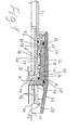
- The invention is explained in more detail below with reference to the drawing, on which
- fig. 1 is a longitudinal section of a nozzle device according to the invention, while
- fig. 2 is a corresponding view of the device shown in another position.
- The shown nozzle device is placed at the end of a
nozzle tube 2, issuing from a spray grip (not shown) connecting with the discharge hose from a high-pressure cleaning unit and provided with a valve, e.g. a pistol grip valve, for opening and closing the outflow from thetube 2. - The nozzle device consists of two main parts axially slideable in relation to one another, viz. an
inner part 4 which is securely connected with the end of thetube 2 and anouter part 6 axially slideable on theinner part 4. Theinner part 4 is a tube bushing having acentral duct 8, at the free end of the bushing issuing into a constricted nozzle opening 10, with one or more wideradial ducts 12 being provided through the wall of thebushing 4 just before the opening 10. - At its external side, the
bushing 4 has at the front a thickenedportion 14 with asealing ring 16 fitted in it. The thickenedportion 14 has at its rear end an additional extended annular area, in which there are local depressions for acceptance ofsteel balls 18. From here, the external side of the bushing extends backwards along a smoothcylindrical surface 20. - The
outer part 6 consists of several joined portions, while, however, being axially slideable as a unit on the inner part. The exterior ofouter part 6 is cylindrical, said part having at its front a constricted orificecylindrical portion 22 with an external, wide ejection opening 24, permitting unobstructed ejection from thecentral nozzle 10. Internally, theouter part 6 has a front, inwardly projectingannular flange 26, engaging the front end of the inner bushing 4in the position shown in fig. 1. From the said flange, the internal side of theouter part 6 extends backwards in arecticylindrical part 28, which seals against sealingring 16 and merges into acylindrical part 30 located behind it, saidpart 30 having a slightly larger diameter. Thispart 30 continues backwards in an extendedcylindrical part 32, in whose wall lengthwise grooves are provided for accepting the external portions of theballs 18. - The
cylindrical part 32 extends slightly backwards to an inwardlyprojecting shoulder 36, which at the innermost side continues backwards in acylindrical part 38, whose diameter is slightly larger than the external diameter of thesurface part 20. Thiscylindrical part 38 terminates at its rear in acylindrical part 40, protruding slightly inwards. The said part sealingly engages thesurface 30 of theinternal bushing 4 by means of a sealingring 42 disposed in thepart 40. The distance between the cylindricalannular area 30 and the inwardly projectingshoulder 36 is designated x in fig. 1. - As a result of this distance x, the entire
outer part 6 is forwardly slideable to the position shown in fig. 2, whereby the distance x appears between the front end of theinner bushing 4 and the rear of theannular flange 26 of the outer part. As will be explained below, theouter section 6 is self-supporting in both of the positions under consideration when ejection is performed through the nozzle device. - The central hole in the
annular flange 26 in front of the nozzle opening 10 is designated 44. Per se it constitutes a discharge nozzle, in front of which are positioned a couple of forwardly protrudinglip plates 46, between their free front ends forming atransverse outflow slot 48. This slot is intended for flattening the ejected jet so as to impart a fan shape to it. - In a preferred embodiment, precisely shown on the drawing, the width of the
slot 48 is adjustable, as thelip plates 46 are arranged so as to be elastic inwardly towards each other. At the external side, eachplate 46 is connected with a protruding boss via a stabilizing device (not described in more detail), said boss being kept engaged with the internal side of the foremost constrictedcylindrical part 22 by an elastic outward pressure from the associatedlip plate 46. Theannular area 52, in which these engaging points occur, is designed so as to have an excentricity causing a more or less extensive compression of the front ends of thelip plates 46 by turning the cylindrical portion, whereby the thickness and the fan angle of the ejected fan jet are stepwise adjustable in both of the said positions of theouter part 6. The rota- tability of thecylindrical part 22 in relation to thelip plates 46 has been achieved by thepart 22 being placed protrudingly from an externalcylindrical portion 54 of theouter part 6, as the said cylindrical portion is journalled slightly rotatably by means offriction rings 56 on aninternal bushing section 58, which at its front supports theannular flange 26, to which thelip plates 46 are secured. Thebushing part 58 is non-rotatably secured to theinner part 4 by means of the saidballs 18 andball grooves 34, so that the entireouter part 6 is slightly axially slideable on theinner part 4, while theouter cylinder slot width 48. - When the
outer part 6 is in a retracted position as shown in fig. 1, the water flows directly to the narrow nozzle opening 10. The water pressure can propagate out through theradial duct 12 to the surrounding annular space between the external side of thebushing part 14 and the internalcylindrical face 30 on theouter part 6, but the sealingring 16 constitutes a block against forwardly moving discharge of water in this space. The water pressure in the space does have a forwardly actuating effect on theouter part 6, but the pressure acts even more rearwardly pushing, as the pressure also propagates backwards, past theballs 18 and back towards the inwardly protrudingshoulder face 36 and onwards into the narrow space between thecylindrical faces ring 42, whereby the rearwardly acting pressure acts on a larger pressure area of the outer part than the forwardly- acting pressure. In this way, the nozzle device will be stabilized in a position in which high-pressure ejection can be achieved through thenarrow nozzle 10. - When it is desired to work with low-pressure ejection, the
outer part 6 of the nozzle should simply be pushed to its foremost position, shown in fig. 2. In this position, theforemost sealing ring 16 on theinternal bushing 4 is brought out of sealing engagement with thecylindrical face 28, and the extendedcylindrical face 30 forms an annular discharge opening 60 together with the front end of theinternal bushing 4. Water can flow forwards through the said opening from the space around theradial ducts 12. The total area of the discharge opening 60 is substantially larger than the area of thecentral nozzle 10 and is also larger than the area of the nozzle opening 44. The water is injected in the space behind the foremostannular flange 26 and from thence it is ejected through nozzle opening 44 and out through the passage between thelip plates 46. - Upon ejection, the water will dynamically cause the
outer part 6 to remain in its protruding position, but in other respects the rearwardly-going static pressure will now only act weakly on the outer part, viz. on the narrow, extreme annular area on theshoulder face 36, so that the outer part is stabilized in its foremost position already at the static pressure. - However, a mechanic holding device may be provided for the
outer part 6 in either of its opposite positions, e.g. a simple resilient ball lock, for which one of theballs 18 could be utilized, so that no unintentional resetting of the outer part can occur, e.g. while ejection is temporarily closed. - It will be within the scope of the invention to provide the construction in such a way that selection between the two nozzles is achieved by turning an operating part, such as the entire external part, while selection with other operating devices is possible when using adjustable lip plates or corresponding flat nozzle edge portions, e.g. also by using a longitudinal slideability of all or part of the external nozzle portion.
- It will also be possible to use the nozzle according to the invention for ejecting pressurized liquid in general, whereby only substantially more liquid will be ejected when opening the
annular outlet 60 and the wide nozzle opening 44.
Claims (5)
Priority Applications (1)
| Application Number | Priority Date | Filing Date | Title |
|---|---|---|---|
| AT84114245T ATE51167T1 (en) | 1983-11-25 | 1984-11-26 | SPRAY NOZZLE FOR CLEANING UNITS WITH HIGH PRESSURE. |
Applications Claiming Priority (2)
| Application Number | Priority Date | Filing Date | Title |
|---|---|---|---|
| DK5390/83 | 1983-11-25 | ||
| DK539083A DK149503C (en) | 1983-11-25 | 1983-11-25 | EXHAUST NOZZLE FOR HIGH PRESSURE CLEANERS |
Publications (3)
| Publication Number | Publication Date |
|---|---|
| EP0146795A2 true EP0146795A2 (en) | 1985-07-03 |
| EP0146795A3 EP0146795A3 (en) | 1987-02-25 |
| EP0146795B1 EP0146795B1 (en) | 1990-03-21 |
Family
ID=8142059
Family Applications (1)
| Application Number | Title | Priority Date | Filing Date |
|---|---|---|---|
| EP84114245A Expired - Lifetime EP0146795B1 (en) | 1983-11-25 | 1984-11-26 | An ejection nozzle for high-pressure cleaning units |
Country Status (6)
| Country | Link |
|---|---|
| US (1) | US4886213A (en) |
| EP (1) | EP0146795B1 (en) |
| JP (1) | JPS60150860A (en) |
| AT (1) | ATE51167T1 (en) |
| DE (1) | DE3481690D1 (en) |
| DK (1) | DK149503C (en) |
Cited By (6)
| Publication number | Priority date | Publication date | Assignee | Title |
|---|---|---|---|---|
| WO1992000150A1 (en) * | 1990-06-29 | 1992-01-09 | Alfred Kärcher GmbH & Co. | High-pressure cleaning device |
| DE4340184A1 (en) * | 1993-11-25 | 1995-06-01 | Anton Jaeger | Spray nozzle partic. for high pressure cleaning devices |
| DE29705444U1 (en) * | 1997-03-26 | 1998-04-23 | Omb Oberdorfer Maschinenfabrik | Adjustable high pressure nozzle |
| DE10257783B3 (en) * | 2002-12-11 | 2004-03-18 | Alfred Kärcher Gmbh & Co. Kg | Nozzle arrangement for a high pressure cleaning device comprises a nozzle hose supporting a pot-shaped housing, and displacement devices moving a low and a high pressure nozzle in the housing against and away from a seal connector |
| WO2006029680A1 (en) * | 2004-09-13 | 2006-03-23 | Washtec Holding Gmbh | Cleaning lance |
| EP3885051A1 (en) | 2020-03-25 | 2021-09-29 | Istobal, S.A. | Automatic switching nozzle |
Families Citing this family (8)
| Publication number | Priority date | Publication date | Assignee | Title |
|---|---|---|---|---|
| IT1245146B (en) * | 1991-02-11 | 1994-09-13 | Faip Off Mecc | PERFECTED NOZZLE FOR HIGH PRESSURE CLEANING MACHINES AND SIMILAR WITH ALIGNED DISPENSING SPOUTS |
| DK171930B1 (en) * | 1996-02-13 | 1997-08-18 | Scanio Flow Equip | Cleaning Systems |
| DE19624333A1 (en) * | 1996-06-19 | 1998-01-08 | Wap Reinigungssysteme | High pressure nozzle for a high pressure cleaning device |
| IT1294939B1 (en) * | 1997-07-31 | 1999-04-23 | Arrow Line Srl | DOUBLE WASHING LANCE WITH AXIAL CONTROL |
| US7871019B1 (en) * | 2009-07-01 | 2011-01-18 | Active Products International Limited | Pressure-adjustable jet spray nozzle for cleaning machine |
| US20140252138A1 (en) * | 2013-03-05 | 2014-09-11 | Generac Power Systems, Inc. | Pressure Washer Adjustable Nozzle Assembly |
| BR112019019584B1 (en) | 2017-03-21 | 2022-08-23 | Coöperatie Avebe U.A | AERED CONFECTIONERY PRODUCT AND STRUCTURING COMPOSITION OF FOAM VEGETARIAN OR VEGAN, METHOD FOR PREPARING SUCH PRODUCT AND USE OF SUCH COMPOSITION |
| CN108187930B (en) * | 2018-01-31 | 2019-06-28 | 江苏大学 | A kind of water-fertilizer-pesticide integrated multi-functional Irrigation shower head |
Citations (4)
| Publication number | Priority date | Publication date | Assignee | Title |
|---|---|---|---|---|
| DE277067C (en) * | ||||
| FR337908A (en) * | 1903-12-21 | 1904-05-03 | Raison Sociale Hassenforder Fr | Lance for water jets |
| FR403253A (en) * | 1909-05-22 | 1909-10-29 | Clement Vacher | Improvements made to nozzles, and sprinkler turnstiles with application |
| US1467807A (en) * | 1920-03-01 | 1923-09-11 | Lewen R Nelson | Nozzle |
Family Cites Families (5)
| Publication number | Priority date | Publication date | Assignee | Title |
|---|---|---|---|---|
| US245096A (en) * | 1881-08-02 | Hose-pipe nozzle | ||
| US583969A (en) * | 1897-06-08 | Joseph askins | ||
| US1319782A (en) * | 1919-10-28 | of detroit | ||
| DE590616C (en) * | 1931-08-30 | 1934-01-06 | August Ziebarth | Jet pipe with changeable mouthpiece width |
| US3102691A (en) * | 1962-06-05 | 1963-09-03 | Sears Roebuck & Co | Hose nozzle |
-
1983
- 1983-11-25 DK DK539083A patent/DK149503C/en not_active IP Right Cessation
-
1984
- 1984-11-21 US US06/673,856 patent/US4886213A/en not_active Expired - Fee Related
- 1984-11-26 AT AT84114245T patent/ATE51167T1/en not_active IP Right Cessation
- 1984-11-26 JP JP59249457A patent/JPS60150860A/en active Pending
- 1984-11-26 DE DE8484114245T patent/DE3481690D1/en not_active Expired - Fee Related
- 1984-11-26 EP EP84114245A patent/EP0146795B1/en not_active Expired - Lifetime
Patent Citations (4)
| Publication number | Priority date | Publication date | Assignee | Title |
|---|---|---|---|---|
| DE277067C (en) * | ||||
| FR337908A (en) * | 1903-12-21 | 1904-05-03 | Raison Sociale Hassenforder Fr | Lance for water jets |
| FR403253A (en) * | 1909-05-22 | 1909-10-29 | Clement Vacher | Improvements made to nozzles, and sprinkler turnstiles with application |
| US1467807A (en) * | 1920-03-01 | 1923-09-11 | Lewen R Nelson | Nozzle |
Cited By (9)
| Publication number | Priority date | Publication date | Assignee | Title |
|---|---|---|---|---|
| WO1992000150A1 (en) * | 1990-06-29 | 1992-01-09 | Alfred Kärcher GmbH & Co. | High-pressure cleaning device |
| DE4340184A1 (en) * | 1993-11-25 | 1995-06-01 | Anton Jaeger | Spray nozzle partic. for high pressure cleaning devices |
| DE29705444U1 (en) * | 1997-03-26 | 1998-04-23 | Omb Oberdorfer Maschinenfabrik | Adjustable high pressure nozzle |
| DE10257783B3 (en) * | 2002-12-11 | 2004-03-18 | Alfred Kärcher Gmbh & Co. Kg | Nozzle arrangement for a high pressure cleaning device comprises a nozzle hose supporting a pot-shaped housing, and displacement devices moving a low and a high pressure nozzle in the housing against and away from a seal connector |
| US7360721B2 (en) | 2002-12-11 | 2008-04-22 | Alfred Kaercher Gmbh & Co. Kg | Nozzle assembly for a high-pressure cleaning device |
| WO2006029680A1 (en) * | 2004-09-13 | 2006-03-23 | Washtec Holding Gmbh | Cleaning lance |
| AU2005256108B2 (en) * | 2004-09-13 | 2008-08-14 | Washtec Holding Gmbh | Cleaning lance |
| US7641133B2 (en) | 2004-09-13 | 2010-01-05 | Washtec Holding Gmbh | Cleaning lance |
| EP3885051A1 (en) | 2020-03-25 | 2021-09-29 | Istobal, S.A. | Automatic switching nozzle |
Also Published As
| Publication number | Publication date |
|---|---|
| ATE51167T1 (en) | 1990-04-15 |
| DK149503C (en) | 1986-12-29 |
| JPS60150860A (en) | 1985-08-08 |
| EP0146795A3 (en) | 1987-02-25 |
| DE3481690D1 (en) | 1990-04-26 |
| EP0146795B1 (en) | 1990-03-21 |
| DK149503B (en) | 1986-07-07 |
| DK539083A (en) | 1985-05-26 |
| DK539083D0 (en) | 1983-11-25 |
| US4886213A (en) | 1989-12-12 |
Similar Documents
| Publication | Publication Date | Title |
|---|---|---|
| US4886213A (en) | Ejection nozzle for high-pressure cleaning units | |
| CA1040236A (en) | Adjustable spray tip | |
| US2376881A (en) | Hose nozzle | |
| US5242116A (en) | Ejection nozzle device for high pressure cleaning apparatus | |
| US5370315A (en) | Spray gun for aggregates | |
| US2478557A (en) | Sprayer and sprayer head for fluent coating materials | |
| US2936960A (en) | Combination adjustable straight stream and fog nozzle | |
| GB923475A (en) | Improvements in or relating to the production of spatter finish coatings | |
| US1929348A (en) | Spray gun | |
| US4216907A (en) | Hydraulic gun | |
| US3414196A (en) | Self-cleaning tip for airless spray guns | |
| US3042315A (en) | Air and liquid spray gun | |
| US1910673A (en) | Spray gun | |
| SE509098C2 (en) | Spray gun for mixing and spraying two media | |
| EP0273677A3 (en) | Flow controller and a high-pressure liquid system | |
| US2842154A (en) | All-purpose fire hose nozzle | |
| US3227378A (en) | Atomizer head | |
| US6616065B2 (en) | Nozzle device | |
| GB1398671A (en) | Spray apparatus | |
| US2283762A (en) | Paint spray nozzle | |
| GB2097911A (en) | Liquid fuel burner | |
| US2763514A (en) | Spray nozzle for fire hose and the like | |
| JP2819425B2 (en) | Fire extinguishing nozzle | |
| GB795283A (en) | Improvements in or relating to jet and atomising dental syringes | |
| US1599592A (en) | Fire-hose nozzle |
Legal Events
| Date | Code | Title | Description |
|---|---|---|---|
| PUAI | Public reference made under article 153(3) epc to a published international application that has entered the european phase |
Free format text: ORIGINAL CODE: 0009012 |
|
| AK | Designated contracting states |
Designated state(s): AT BE CH DE FR GB IT LI LU NL SE |
|
| PUAL | Search report despatched |
Free format text: ORIGINAL CODE: 0009013 |
|
| AK | Designated contracting states |
Kind code of ref document: A3 Designated state(s): AT BE CH DE FR GB IT LI LU NL SE |
|
| 17P | Request for examination filed |
Effective date: 19870226 |
|
| 17Q | First examination report despatched |
Effective date: 19880509 |
|
| RAP1 | Party data changed (applicant data changed or rights of an application transferred) |
Owner name: K.E.W. INDUSTRI A/S |
|
| GRAA | (expected) grant |
Free format text: ORIGINAL CODE: 0009210 |
|
| AK | Designated contracting states |
Kind code of ref document: B1 Designated state(s): AT BE CH DE FR GB IT LI LU NL SE |
|
| REF | Corresponds to: |
Ref document number: 51167 Country of ref document: AT Date of ref document: 19900415 Kind code of ref document: T |
|
| ITF | It: translation for a ep patent filed |
Owner name: ING. A. GIAMBROCONO & C. S.R.L. |
|
| REF | Corresponds to: |
Ref document number: 3481690 Country of ref document: DE Date of ref document: 19900426 |
|
| ET | Fr: translation filed | ||
| PGFP | Annual fee paid to national office [announced via postgrant information from national office to epo] |
Ref country code: LU Payment date: 19901022 Year of fee payment: 7 |
|
| PGFP | Annual fee paid to national office [announced via postgrant information from national office to epo] |
Ref country code: FR Payment date: 19901030 Year of fee payment: 7 Ref country code: BE Payment date: 19901030 Year of fee payment: 7 |
|
| PGFP | Annual fee paid to national office [announced via postgrant information from national office to epo] |
Ref country code: GB Payment date: 19901119 Year of fee payment: 7 |
|
| PGFP | Annual fee paid to national office [announced via postgrant information from national office to epo] |
Ref country code: SE Payment date: 19901121 Year of fee payment: 7 |
|
| PGFP | Annual fee paid to national office [announced via postgrant information from national office to epo] |
Ref country code: AT Payment date: 19901126 Year of fee payment: 7 |
|
| PGFP | Annual fee paid to national office [announced via postgrant information from national office to epo] |
Ref country code: CH Payment date: 19901128 Year of fee payment: 7 |
|
| PG25 | Lapsed in a contracting state [announced via postgrant information from national office to epo] |
Ref country code: LU Free format text: LAPSE BECAUSE OF NON-PAYMENT OF DUE FEES Effective date: 19901130 |
|
| PGFP | Annual fee paid to national office [announced via postgrant information from national office to epo] |
Ref country code: NL Payment date: 19901130 Year of fee payment: 7 |
|
| PGFP | Annual fee paid to national office [announced via postgrant information from national office to epo] |
Ref country code: DE Payment date: 19901228 Year of fee payment: 7 |
|
| PLBI | Opposition filed |
Free format text: ORIGINAL CODE: 0009260 |
|
| 26 | Opposition filed |
Opponent name: INTERPUMP SPA Effective date: 19901215 Opponent name: OFFICINE MECCANICHE FAIP S.R.L. Effective date: 19901218 |
|
| EPTA | Lu: last paid annual fee | ||
| NLR1 | Nl: opposition has been filed with the epo |
Opponent name: INTERPUMP SPA Opponent name: OFFICINE MECCANICHE FAIP S.R.L. |
|
| PG25 | Lapsed in a contracting state [announced via postgrant information from national office to epo] |
Ref country code: GB Effective date: 19911126 Ref country code: AT Effective date: 19911126 |
|
| PG25 | Lapsed in a contracting state [announced via postgrant information from national office to epo] |
Ref country code: SE Effective date: 19911127 |
|
| ITTA | It: last paid annual fee | ||
| PG25 | Lapsed in a contracting state [announced via postgrant information from national office to epo] |
Ref country code: LI Effective date: 19911130 Ref country code: CH Effective date: 19911130 Ref country code: BE Effective date: 19911130 |
|
| BERE | Be: lapsed |
Owner name: K.E.W. INDUSTRI A/S Effective date: 19911130 |
|
| PG25 | Lapsed in a contracting state [announced via postgrant information from national office to epo] |
Ref country code: NL Effective date: 19920601 |
|
| NLV4 | Nl: lapsed or anulled due to non-payment of the annual fee | ||
| GBPC | Gb: european patent ceased through non-payment of renewal fee | ||
| PG25 | Lapsed in a contracting state [announced via postgrant information from national office to epo] |
Ref country code: FR Effective date: 19920731 |
|
| REG | Reference to a national code |
Ref country code: CH Ref legal event code: PL |
|
| PG25 | Lapsed in a contracting state [announced via postgrant information from national office to epo] |
Ref country code: DE Effective date: 19920801 |
|
| REG | Reference to a national code |
Ref country code: FR Ref legal event code: ST |
|
| PLBM | Termination of opposition procedure: date of legal effect published |
Free format text: ORIGINAL CODE: 0009276 |
|
| STAA | Information on the status of an ep patent application or granted ep patent |
Free format text: STATUS: OPPOSITION PROCEDURE CLOSED |
|
| 27C | Opposition proceedings terminated |
Effective date: 19921123 |
|
| EUG | Se: european patent has lapsed |
Ref document number: 84114245.8 Effective date: 19920604 |
|
| PLAB | Opposition data, opponent's data or that of the opponent's representative modified |
Free format text: ORIGINAL CODE: 0009299OPPO |