EP0146110B1 - Device for manufacturing cross-grooves on length-wise grooved bottom plates, etc. - Google Patents
Device for manufacturing cross-grooves on length-wise grooved bottom plates, etc. Download PDFInfo
- Publication number
- EP0146110B1 EP0146110B1 EP19840115202 EP84115202A EP0146110B1 EP 0146110 B1 EP0146110 B1 EP 0146110B1 EP 19840115202 EP19840115202 EP 19840115202 EP 84115202 A EP84115202 A EP 84115202A EP 0146110 B1 EP0146110 B1 EP 0146110B1
- Authority
- EP
- European Patent Office
- Prior art keywords
- drive shaft
- grooves
- length
- bottom plates
- profiles
- Prior art date
- Legal status (The legal status is an assumption and is not a legal conclusion. Google has not performed a legal analysis and makes no representation as to the accuracy of the status listed.)
- Expired
Links
Images


Classifications
-
- B—PERFORMING OPERATIONS; TRANSPORTING
- B23—MACHINE TOOLS; METAL-WORKING NOT OTHERWISE PROVIDED FOR
- B23C—MILLING
- B23C1/00—Milling machines not designed for particular work or special operations
- B23C1/20—Portable devices or machines; Hand-driven devices or machines
-
- B—PERFORMING OPERATIONS; TRANSPORTING
- B23—MACHINE TOOLS; METAL-WORKING NOT OTHERWISE PROVIDED FOR
- B23Q—DETAILS, COMPONENTS, OR ACCESSORIES FOR MACHINE TOOLS, e.g. ARRANGEMENTS FOR COPYING OR CONTROLLING; MACHINE TOOLS IN GENERAL CHARACTERISED BY THE CONSTRUCTION OF PARTICULAR DETAILS OR COMPONENTS; COMBINATIONS OR ASSOCIATIONS OF METAL-WORKING MACHINES, NOT DIRECTED TO A PARTICULAR RESULT
- B23Q35/00—Control systems or devices for copying directly from a pattern or a master model; Devices for use in copying manually
- B23Q35/04—Control systems or devices for copying directly from a pattern or a master model; Devices for use in copying manually using a feeler or the like travelling along the outline of the pattern, model or drawing; Feelers, patterns, or models therefor
- B23Q35/08—Means for transforming movement of the feeler or the like into feed movement of tool or work
- B23Q35/10—Means for transforming movement of the feeler or the like into feed movement of tool or work mechanically only
- B23Q35/101—Means for transforming movement of the feeler or the like into feed movement of tool or work mechanically only with a pattern composed of one or more lines used simultaneously for one tool
- B23Q35/105—Means for transforming movement of the feeler or the like into feed movement of tool or work mechanically only with a pattern composed of one or more lines used simultaneously for one tool of two lines
- B23Q35/106—Means for transforming movement of the feeler or the like into feed movement of tool or work mechanically only with a pattern composed of one or more lines used simultaneously for one tool of two lines with a single tool and two feelers rotating about parallel axis
-
- B—PERFORMING OPERATIONS; TRANSPORTING
- B23—MACHINE TOOLS; METAL-WORKING NOT OTHERWISE PROVIDED FOR
- B23Q—DETAILS, COMPONENTS, OR ACCESSORIES FOR MACHINE TOOLS, e.g. ARRANGEMENTS FOR COPYING OR CONTROLLING; MACHINE TOOLS IN GENERAL CHARACTERISED BY THE CONSTRUCTION OF PARTICULAR DETAILS OR COMPONENTS; COMBINATIONS OR ASSOCIATIONS OF METAL-WORKING MACHINES, NOT DIRECTED TO A PARTICULAR RESULT
- B23Q9/00—Arrangements for supporting or guiding portable metal-working machines or apparatus
- B23Q9/0014—Portable machines provided with or cooperating with guide means supported directly by the workpiece during action
- B23Q9/0028—Portable machines provided with or cooperating with guide means supported directly by the workpiece during action the guide means being fixed only on the machine
Definitions
- the invention relates to a device for producing transverse corrugation on longitudinally ribbed surfaces of non-slip base plates or the like. Profiles according to the preamble of claim 1.
- checkered plates are used in addition to checkered plates and plates with sprayed-on or glued-on anti-slip coverings, but these are only transverse to the pressing direction are non-slip.
- a device (CH-A-315529) has become known for machining blocks of stone, which mills a network of transverse incisions after the longitudinal grooves have been cut. For this purpose, this milling machine is moved on guide rails attached to the stone surface. On a motor-driven, parallel to the rock face and transverse to the rail direction working shaft adjustable rock cutters are arranged at a distance.
- this milling machine Since this milling machine is dependent on additional guide rails, it cannot be used for cross-grooving of already longitudinally ribbed profiles, because the laying of the guide rails on the profiles to be machined is very complex and, in addition, the pressing tolerances and unevenness on the profiles due to the rail guidance cannot be compensated.
- a knife roller In another machine for the machining of surfaces (DE-A-2 552 484), a knife roller is mounted in a housing to be guided over the surface. To determine the milling depth, this knife roller is supported by support plates that slide over the surface to be machined. Since when using this milling machine on longitudinally ribbed profiles the support plates as spacers in turn slide over several longitudinal ribs, the above-mentioned defects cannot be remedied with this device either.
- the invention is therefore based on the object of providing a device for producing transverse corrugation on longitudinally ribbed profiles, which ensures transverse corrugation that matches the profile base area.
- An additional guide roller can be attached to a housing for guiding the drive shaft.
- the feed movement of the device is preferably accomplished manually or also mechanically.
- the device runs in a guide frame, the contact pressure on the plateau or the profile must be done via spring force or shock absorber so that the unevenness of the surface can be compensated.
- a profile 1 is shown in cross-section and in plan view, the cross-sectional view showing the unevenness on the surface - greatly exaggerated.
- the longitudinal ribs 2 have already been cut out on one half to form a transverse corrugation 3.
- the longitudinal ribs 2 are still shown continuously on the second surface half.
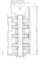
- Fig. 2 shows a complete cutting device with gear-like support wheels 4.
- a support wheel 4 shown partially in section, rolls on the base of the profile 1 between the longitudinal ribs 2 and thus holds a milling cutter blade 5 at a precise distance from the base of the profile 1 because of The diameter of the support wheel is slightly larger than that of the milling cutter blade 5.
- Any number of milling cutter blades 5 are keyed onto a drive shaft 6, while the outer support wheels 4 are loosely rotatably supported on this shaft 6.
- a housing 7 connects the drive shaft to a front guide wheel 8 for the purpose of better guiding the device. Either by hand or when using a rigid guide frame by means of spring force, the device is loaded at 9 for pressing onto the profile to be machined.
- Fig. 1 shows a complete cutting device with gear-like support wheels 4.
- a support wheel 4 shown partially in section, rolls on the base of the profile 1 between the longitudinal ribs 2 and thus holds a milling cutter blade 5 at a precise distance from the base of the profile 1 because of
- this cutting device is shown in cross section.
- the two outside support wheels 4, which keep the distance to the surface of the profile and the milling cutter blades 5 in between can be seen more clearly.
- Spacer sleeves 12 keep the distance between the cutter blades.
- a drive 13 of the shaft 6 is electrical or otherwise and is attached to the housing.
Description
Die Erfindung betrifft eine Vorrichtung zum Herstellen einer Querriffelung an längsgerippten Oberflächen von rutschfesten Bodenplatten od. dgl. Profilen gemäß dem Oberbegriff des Patentanspruches 1.The invention relates to a device for producing transverse corrugation on longitudinally ribbed surfaces of non-slip base plates or the like. Profiles according to the preamble of claim 1.
Um auf begehbaren Plattformen od. dgl. Flächen, insbesondere auf Ladebordwandplateaus, Lastkraftwagen-Plateaus, Treppen, Trittflächen usw. eine rutschsichere Oberfläche zu schaffen, werden neben Warzenblechen und Blechen mit aufgespritzten oder aufgeklebten Antirutschbelägen auch geriffelte Strangpreßprofile verwendet, die aber nur quer zur Preßrichtung rutschsicher sind. In der Praxis wurde aber auch schon bekannt, die Längsrippen stellenweise durch Walzen zu quetschen oder durch Fräsen oder Stanzen in geeigneten Maschinenanlagen zu unterbrechen, um dadurch die Rutschsicherheit auch in Preßrichtung zu gewährleisten. Dabei ergeben sich aber unterschiedlich tiefe Querriffelungen, da die Profile infolge nicht zu vermeidender Preßtoleranzen meist unebene Oberflächen aufweisen. Werden dann die Einzelprofile mit den Querriffelungen zu einer Plattenform zusammengebaut, so ist es schwierig, eine Ausrichtung in Querrichtung, die auch optisch entspricht, zu bekommen. Zudem werden beim Zusammenbau häufig noch größere Verschnitte an den Profilen erforderlich. Zum Bearbeiten von Gesteinsblöcken ist eine Vorrichtung (CH-A-315529) bekanntgeworden, die nach dem Einschneiden von Längsnuten ein Netz von querverlaufenden Einschnitten einfräst. Dazu wird diese Fräsmaschine auf auf der Gesteinsfläche befestigten Führungsschienen verschoben. Auf einer motorisch angetriebenen, zur Gesteinsfläche parallelen und quer zur Schienenrichtung verlaufenden Arbeitswelle sind auf Distanz einstellbare Gesteinsfräser angeordnet. Da diese Fräsmaschine auf zusätzliche Führungsschienen angewiesen ist, ist sie zum Querriffeln von bereits längsgerippten Profilen nicht brauchbar, weil das Verlegen der Führungsschienen auf den zu bearbeitenden Profilen sehr aufwendig ist und außerdem die Preßtoleranzen und Unebenheiten an den Profilen infolge der Schienenführung nicht ausgeglichen werden können. Bei einer anderen Maschine für die spanabhebende Bearbeitung von Flächen (DE-A-2 552 484) ist eine Messerwalze in einem über die Fläche zu führenden Gehäuse gelagert. Zur Festlegung der Frästiefe wird diese Messerwalze von über die zu bearbeitende Fläche gleitenden Auflageplatten abgestützt. Da beim Einsatz dieser Fräsmaschine auf längsgerippten Profilen die Auflageplatten als Abstandhalter wiederum über mehrere Längsrippen gleiten, können auch mit dieser Vorrichtung die vorerwähnten Mängel nicht behoben werden.In order to create a non-slip surface on walk-on platforms or similar surfaces, in particular on loading platform plateaus, truck plateaus, stairs, treads, etc., checkered plates are used in addition to checkered plates and plates with sprayed-on or glued-on anti-slip coverings, but these are only transverse to the pressing direction are non-slip. In practice, however, it has also been known to squeeze the longitudinal ribs in places by rolling or to interrupt them by milling or punching in suitable machine systems, in order to ensure that they also slip in the pressing direction. This results in cross-corrugations of different depths, since the profiles usually have uneven surfaces due to unavoidable pressing tolerances. If the individual profiles with the transverse corrugations are then assembled into a plate shape, it is difficult to obtain an orientation in the transverse direction that also corresponds optically. In addition, even larger cuts on the profiles are often required during assembly. A device (CH-A-315529) has become known for machining blocks of stone, which mills a network of transverse incisions after the longitudinal grooves have been cut. For this purpose, this milling machine is moved on guide rails attached to the stone surface. On a motor-driven, parallel to the rock face and transverse to the rail direction working shaft adjustable rock cutters are arranged at a distance. Since this milling machine is dependent on additional guide rails, it cannot be used for cross-grooving of already longitudinally ribbed profiles, because the laying of the guide rails on the profiles to be machined is very complex and, in addition, the pressing tolerances and unevenness on the profiles due to the rail guidance cannot be compensated. In another machine for the machining of surfaces (DE-A-2 552 484), a knife roller is mounted in a housing to be guided over the surface. To determine the milling depth, this knife roller is supported by support plates that slide over the surface to be machined. Since when using this milling machine on longitudinally ribbed profiles the support plates as spacers in turn slide over several longitudinal ribs, the above-mentioned defects cannot be remedied with this device either.
Der Erfindung liegt daher die Aufgabe zugrunde, eine Vorrichtung zum Herstellen einer Querriffelung an längsgerippten Profilen zu schaffen, die eine mit der Profil-Grundfläche übereinstimmende Querriffelung gewährleistet.The invention is therefore based on the object of providing a device for producing transverse corrugation on longitudinally ribbed profiles, which ensures transverse corrugation that matches the profile base area.
Diese Aufgabe wird mit einer Vorrichtung gemäß dem Oberbegriff des Patentanspruches 1 erfindungsgemäß durch die kennzeichnenden Merkmale dieses Patentanspruches gelöst.This object is achieved with a device according to the preamble of claim 1 according to the invention by the characterizing features of this claim.
Durch die Abstützung der mit den Fräserblättern ausgerüsteten Antriebswelle mit Stützrädern, die auf der Grundfläche der Profile abrollen, wird eine örtliche Anpassung an die Unebenheiten der Profiloberfläche und damit eine gleiche Einschnittiefe in die Längsrippen erreicht. Dadurch können auch zu Plattformen zusammengesetzte Profile bearbeitet und dabei gleich tiefe Querriffelungen gewonnen werden.By supporting the drive shaft equipped with the milling cutter blades with support wheels that roll on the base of the profiles, a local adaptation to the unevenness of the profile surface and thus an equal incision depth in the longitudinal ribs is achieved. As a result, profiles assembled into platforms can also be machined and transverse corrugations of the same depth obtained.
Zur Führung der Antriebswelle kann an einem Gehäuse eine zusätzliche Führungsrolle angebracht sein.An additional guide roller can be attached to a housing for guiding the drive shaft.
Die Vorschubbewegung der Vorrichtung wird vorzugsweise von Hand oder auch mechanisch bewerkstelligt. Bei der mechanischen Bewegung läuft die Vorrichtung in einem Führungsrahmen, der Anpreßdruck auf das Plateau bzw. das Profil muß dabei über Federkraft oder Stoßdämpfer erfolgen, damit die Ungleichmäßigkeiten der Oberfläche ausgeglichen werden können.The feed movement of the device is preferably accomplished manually or also mechanically. During the mechanical movement, the device runs in a guide frame, the contact pressure on the plateau or the profile must be done via spring force or shock absorber so that the unevenness of the surface can be compensated.
Die Erfindung wird nachfolgend an einem Ausführungsbeispiel, das auch in der Zeichnung dargestellt ist, näher beschrieben. Es zeigen :
- Fig. 1 und Fig. 1a ein zu bearbeitendes Profil im Querschnitt und Draufsicht,
- Fig. 2 einen Schnitt durch eine Schneidvorrichtung und
- Fig. 3 einen Querschnitt nach der Linie V-V der Fig. 2.
- 1 and Fig. 1a a profile to be machined in cross section and top view,
- Fig. 2 shows a section through a cutting device and
- 3 shows a cross section along the line VV of FIG. 2nd
In Fig. 1 ist ein Profil 1 im Querschnitt und in Draufsicht dargestellt, wobei die Querschnittsdarstellung die Unebenheiten an der Oberfläche - stark übertrieben - erkennen läßt. Die Längsrippen 2 sind schon auf der einen Hälfte ausgeschnitten, um eine Querriffelung 3 zu bilden. Auf der zweiten Flächenhälfte sind die Längsrippen 2 noch durchgehend dargestellt.In Fig. 1, a profile 1 is shown in cross-section and in plan view, the cross-sectional view showing the unevenness on the surface - greatly exaggerated. The
Fig. 2 zeigt eine komplette Schneidvorrichtung mit zahnradartigen Stützrädern 4. Ein Stützrad 4, teilweise geschnitten dargestellt, wälzt sich auf der Grundfläche des Profiles 1 zwischen den Längsrippen 2 ab und hält so ein Fräserblatt 5 auf genaue Distanz zur Grundfläche des Profiles 1, weil der Durchmesser des Stützrades etwas größer ist als der des Fräserblattes 5. Beliebig viele Fräserblätter 5 sind auf einer Antriebswelle 6 aufgekeilt, während die äußeren Stützräder 4 lose auf dieser Welle 6 drehbar gelagert sind. Ein Gehäuse 7 verbindet die Antriebswelle mit einem vorderen Führungsrad 8 zum Zwecke der besseren Führung der Vorrichtung. Entweder von Hand oder bei Verwendung eines starren Führungsrahmens mittels Federkraft wird die Vorrichtung bei 9 zum Andrücken auf das zu bearbeitende Profil belastet. In Fig. 3 ist diese Schneidvorrichtung im Querschnitt dargestellt. Dabei sind die beiden außenseitig angeordneten Stützräder 4, die die Distanz zur Oberfläche des Profiles halten und die dazwischenliegenden Fräserblätter 5 deutlicher zu sehen. Distanzbüchsen 12 halten den Abstand zwischen den Fräserblättern. Ein Antrieb 13 der Welle 6 erfolgt elektrisch oder anderweitig und ist am Gehäuse befestigt.Fig. 2 shows a complete cutting device with gear-
Claims (2)
Applications Claiming Priority (2)
| Application Number | Priority Date | Filing Date | Title |
|---|---|---|---|
| AT0436583A AT381265B (en) | 1983-12-15 | 1983-12-15 | METHOD AND DEVICE FOR PRODUCING CROSS-RIFLING ON LONG-RIBBED SURFACES |
| AT4365/83 | 1983-12-15 |
Publications (3)
| Publication Number | Publication Date |
|---|---|
| EP0146110A2 EP0146110A2 (en) | 1985-06-26 |
| EP0146110A3 EP0146110A3 (en) | 1987-08-05 |
| EP0146110B1 true EP0146110B1 (en) | 1989-10-11 |
Family
ID=3563044
Family Applications (1)
| Application Number | Title | Priority Date | Filing Date |
|---|---|---|---|
| EP19840115202 Expired EP0146110B1 (en) | 1983-12-15 | 1984-12-12 | Device for manufacturing cross-grooves on length-wise grooved bottom plates, etc. |
Country Status (3)
| Country | Link |
|---|---|
| EP (1) | EP0146110B1 (en) |
| AT (1) | AT381265B (en) |
| DE (1) | DE3480061D1 (en) |
Families Citing this family (2)
| Publication number | Priority date | Publication date | Assignee | Title |
|---|---|---|---|---|
| GB9421769D0 (en) * | 1994-10-28 | 1994-12-14 | Black & Decker Inc | Jigsaw |
| DE10004470C2 (en) * | 2000-02-02 | 2003-10-02 | Reich Spezialmaschinen Gmbh | Process for milling a groove in a plate-shaped workpiece and processing machine for carrying out the process |
Family Cites Families (6)
| Publication number | Priority date | Publication date | Assignee | Title |
|---|---|---|---|---|
| CH315529A (en) * | 1953-10-28 | 1956-08-31 | Denes Zoltan | Method for cutting out stone blocks from the natural rock in a stone pit and system for carrying out this method |
| US3011530A (en) * | 1959-07-13 | 1961-12-05 | Lamb Ellard | Guide for portable saw |
| FR2256807A1 (en) * | 1974-01-07 | 1975-08-01 | Merzeau Jean Alain | Woodworking tool forming slots - has multiple sets of toothed rotary cutters and spacers altered to vary spacing of slots |
| DE2552484A1 (en) * | 1975-11-22 | 1977-05-26 | Helmut Meyer | MACHINE FOR THE MACHINING OF SURFACES |
| US4188934A (en) * | 1978-10-20 | 1980-02-19 | Cushion Cut, Inc. | Step safety groover apparatus |
| DE3145913C1 (en) * | 1981-11-19 | 1983-10-06 | Fritz Fleissner | Milling tool for a hand-guided milling device, for milling an inner shoulder on a gemstone setting |
-
1983
- 1983-12-15 AT AT0436583A patent/AT381265B/en not_active IP Right Cessation
-
1984
- 1984-12-12 EP EP19840115202 patent/EP0146110B1/en not_active Expired
- 1984-12-12 DE DE8484115202T patent/DE3480061D1/en not_active Expired
Also Published As
| Publication number | Publication date |
|---|---|
| ATA436583A (en) | 1986-02-15 |
| EP0146110A2 (en) | 1985-06-26 |
| EP0146110A3 (en) | 1987-08-05 |
| DE3480061D1 (en) | 1989-11-16 |
| AT381265B (en) | 1986-09-25 |
Similar Documents
| Publication | Publication Date | Title |
|---|---|---|
| EP1820902B1 (en) | Travelling device for milling rail heads | |
| EP1301663A1 (en) | Method for re-profiling at least one running surface of a rail, and corresponding device | |
| DD152378A5 (en) | METHOD AND DRIVE MACHINE FOR REMOVING IRREGULARITIES IN THE LAYER OF THE LAYER OF THE LAYER | |
| DD281620A5 (en) | BAND GRINDING UNIT FOR GRINDING UNREGULARITY ON THE RAILING COPPER LAYOUT OF ONE OR BOTH RAILS OF A TRACKING TRACK | |
| DE3806116A1 (en) | DEVICE FOR POSITIONING ARC-SHAPED CROSSBODY FRAME PARTS AND MILLING KEYSTONE EXCEPTIONS IN THESE FRAME PARTS | |
| EP0146110B1 (en) | Device for manufacturing cross-grooves on length-wise grooved bottom plates, etc. | |
| EP1862232A1 (en) | Extruded profile, in particular floor profile | |
| WO2002055247A2 (en) | Cutting system | |
| CH649592A5 (en) | TRACKABLE PLANING MACHINE WITH PLANING TOOL. | |
| EP0389914A1 (en) | Pressure beam for belt sander | |
| DE3821287A1 (en) | MACHINE FOR BEVELING PANELS, ESPECIALLY GLASS DISKS | |
| EP2149416A2 (en) | Pressure bar saw | |
| DE2519350A1 (en) | Woodworking machine workpieces feed device - separate travelling carriages ld workpiece without danger to operator | |
| DE1752117B2 (en) | Planing or milling device arranged on plate shears | |
| DE3340466A1 (en) | Device for making welding grooves | |
| DE2636468A1 (en) | COPY MILLING MACHINE | |
| DE2832174C3 (en) | Machine for cutting the corners of panels arranged in stacks | |
| AT406129B (en) | DEVICE FOR MACHINING A STRIP-SHAPED WORKPIECE SURFACE | |
| DE4310631C2 (en) | Feed device for profiling window bars made of wood or the like. | |
| DE3305666A1 (en) | Continuous calibrating machine for granite plates | |
| DE926424C (en) | Method and device for the production of cutouts in metal strips or bands | |
| DE566091C (en) | Linoleum hand cutting device | |
| DE2439669A1 (en) | Butt weld for flat plates - grinding wheel cuts groove along rear of initial weld | |
| DE102004063687A1 (en) | Shaping process for flat workpieces involves making at least one groove in region of profile of side edge being shaped | |
| EP0314152B1 (en) | Planing machine |
Legal Events
| Date | Code | Title | Description |
|---|---|---|---|
| PUAI | Public reference made under article 153(3) epc to a published international application that has entered the european phase |
Free format text: ORIGINAL CODE: 0009012 |
|
| AK | Designated contracting states |
Designated state(s): CH DE FR LI NL SE |
|
| RTI1 | Title (correction) | ||
| RAP1 | Party data changed (applicant data changed or rights of an application transferred) |
Owner name: AUSTRIA METALL AKTIENGESELLSCHAFT |
|
| PUAL | Search report despatched |
Free format text: ORIGINAL CODE: 0009013 |
|
| AK | Designated contracting states |
Kind code of ref document: A3 Designated state(s): CH DE FR LI NL SE |
|
| 17P | Request for examination filed |
Effective date: 19871211 |
|
| 17Q | First examination report despatched |
Effective date: 19880601 |
|
| GRAA | (expected) grant |
Free format text: ORIGINAL CODE: 0009210 |
|
| AK | Designated contracting states |
Kind code of ref document: B1 Designated state(s): CH DE FR LI NL SE |
|
| REF | Corresponds to: |
Ref document number: 3480061 Country of ref document: DE Date of ref document: 19891116 |
|
| ET | Fr: translation filed | ||
| PLBE | No opposition filed within time limit |
Free format text: ORIGINAL CODE: 0009261 |
|
| STAA | Information on the status of an ep patent application or granted ep patent |
Free format text: STATUS: NO OPPOSITION FILED WITHIN TIME LIMIT |
|
| 26N | No opposition filed | ||
| PGFP | Annual fee paid to national office [announced via postgrant information from national office to epo] |
Ref country code: SE Payment date: 19901221 Year of fee payment: 7 |
|
| PGFP | Annual fee paid to national office [announced via postgrant information from national office to epo] |
Ref country code: NL Payment date: 19901231 Year of fee payment: 7 Ref country code: FR Payment date: 19901231 Year of fee payment: 7 |
|
| PGFP | Annual fee paid to national office [announced via postgrant information from national office to epo] |
Ref country code: DE Payment date: 19910124 Year of fee payment: 7 |
|
| PGFP | Annual fee paid to national office [announced via postgrant information from national office to epo] |
Ref country code: CH Payment date: 19910227 Year of fee payment: 7 |
|
| PG25 | Lapsed in a contracting state [announced via postgrant information from national office to epo] |
Ref country code: SE Effective date: 19911213 |
|
| PG25 | Lapsed in a contracting state [announced via postgrant information from national office to epo] |
Ref country code: LI Effective date: 19911231 Ref country code: CH Effective date: 19911231 |
|
| PG25 | Lapsed in a contracting state [announced via postgrant information from national office to epo] |
Ref country code: NL Effective date: 19920701 |
|
| NLV4 | Nl: lapsed or anulled due to non-payment of the annual fee | ||
| PG25 | Lapsed in a contracting state [announced via postgrant information from national office to epo] |
Ref country code: FR Effective date: 19920831 |
|
| REG | Reference to a national code |
Ref country code: CH Ref legal event code: PL |
|
| PG25 | Lapsed in a contracting state [announced via postgrant information from national office to epo] |
Ref country code: DE Effective date: 19920901 |
|
| REG | Reference to a national code |
Ref country code: FR Ref legal event code: ST |
|
| EUG | Se: european patent has lapsed |
Ref document number: 84115202.8 Effective date: 19920704 |