EP0145860B1 - Palette zur Aufnahme von Aufsatzspannbacken - Google Patents
Palette zur Aufnahme von Aufsatzspannbacken Download PDFInfo
- Publication number
- EP0145860B1 EP0145860B1 EP84111268A EP84111268A EP0145860B1 EP 0145860 B1 EP0145860 B1 EP 0145860B1 EP 84111268 A EP84111268 A EP 84111268A EP 84111268 A EP84111268 A EP 84111268A EP 0145860 B1 EP0145860 B1 EP 0145860B1
- Authority
- EP
- European Patent Office
- Prior art keywords
- pallet
- jaws
- clamping bolts
- auxiliary jaws
- clamping
- Prior art date
- Legal status (The legal status is an assumption and is not a legal conclusion. Google has not performed a legal analysis and makes no representation as to the accuracy of the status listed.)
- Expired
Links
- 239000000725 suspension Substances 0.000 claims description 2
- 230000004308 accommodation Effects 0.000 claims 1
- 230000008878 coupling Effects 0.000 description 3
- 238000010168 coupling process Methods 0.000 description 3
- 238000005859 coupling reaction Methods 0.000 description 3
- 230000006835 compression Effects 0.000 description 2
- 238000007906 compression Methods 0.000 description 2
- 238000010276 construction Methods 0.000 description 2
- 238000006073 displacement reaction Methods 0.000 description 1
- 238000003780 insertion Methods 0.000 description 1
- 230000037431 insertion Effects 0.000 description 1
- 238000003754 machining Methods 0.000 description 1
- 238000004519 manufacturing process Methods 0.000 description 1
- 210000002445 nipple Anatomy 0.000 description 1
Images


Classifications
-
- B—PERFORMING OPERATIONS; TRANSPORTING
- B23—MACHINE TOOLS; METAL-WORKING NOT OTHERWISE PROVIDED FOR
- B23B—TURNING; BORING
- B23B31/00—Chucks; Expansion mandrels; Adaptations thereof for remote control
- B23B31/02—Chucks
- B23B31/39—Jaw changers
-
- B—PERFORMING OPERATIONS; TRANSPORTING
- B23—MACHINE TOOLS; METAL-WORKING NOT OTHERWISE PROVIDED FOR
- B23B—TURNING; BORING
- B23B31/00—Chucks; Expansion mandrels; Adaptations thereof for remote control
- B23B31/02—Chucks
- B23B31/10—Chucks characterised by the retaining or gripping devices or their immediate operating means
- B23B31/12—Chucks with simultaneously-acting jaws, whether or not also individually adjustable
- B23B31/16—Chucks with simultaneously-acting jaws, whether or not also individually adjustable moving radially
- B23B31/16045—Jaws movement actuated by screws and nuts or oblique racks
- B23B31/1605—Details of the jaws
- B23B31/16058—Fixation on the master jaw
-
- Y—GENERAL TAGGING OF NEW TECHNOLOGICAL DEVELOPMENTS; GENERAL TAGGING OF CROSS-SECTIONAL TECHNOLOGIES SPANNING OVER SEVERAL SECTIONS OF THE IPC; TECHNICAL SUBJECTS COVERED BY FORMER USPC CROSS-REFERENCE ART COLLECTIONS [XRACs] AND DIGESTS
- Y10—TECHNICAL SUBJECTS COVERED BY FORMER USPC
- Y10T—TECHNICAL SUBJECTS COVERED BY FORMER US CLASSIFICATION
- Y10T29/00—Metal working
- Y10T29/51—Plural diverse manufacturing apparatus including means for metal shaping or assembling
- Y10T29/5124—Plural diverse manufacturing apparatus including means for metal shaping or assembling with means to feed work intermittently from one tool station to another
-
- Y—GENERAL TAGGING OF NEW TECHNOLOGICAL DEVELOPMENTS; GENERAL TAGGING OF CROSS-SECTIONAL TECHNOLOGIES SPANNING OVER SEVERAL SECTIONS OF THE IPC; TECHNICAL SUBJECTS COVERED BY FORMER USPC CROSS-REFERENCE ART COLLECTIONS [XRACs] AND DIGESTS
- Y10—TECHNICAL SUBJECTS COVERED BY FORMER USPC
- Y10T—TECHNICAL SUBJECTS COVERED BY FORMER US CLASSIFICATION
- Y10T483/00—Tool changing
- Y10T483/17—Tool changing including machine tool or component
- Y10T483/1702—Rotating work machine tool [e.g., screw machine, lathe, etc.]
- Y10T483/1707—Tool having specific mounting or work treating feature
- Y10T483/171—Workpiece holder [e.g., chuck or chuck jaw, collet, etc.]
-
- Y—GENERAL TAGGING OF NEW TECHNOLOGICAL DEVELOPMENTS; GENERAL TAGGING OF CROSS-SECTIONAL TECHNOLOGIES SPANNING OVER SEVERAL SECTIONS OF THE IPC; TECHNICAL SUBJECTS COVERED BY FORMER USPC CROSS-REFERENCE ART COLLECTIONS [XRACs] AND DIGESTS
- Y10—TECHNICAL SUBJECTS COVERED BY FORMER USPC
- Y10T—TECHNICAL SUBJECTS COVERED BY FORMER US CLASSIFICATION
- Y10T82/00—Turning
- Y10T82/25—Lathe
- Y10T82/2514—Lathe with work feeder or remover
- Y10T82/2516—Magazine type
Definitions
- the invention relates to a pallet for receiving top jaws which can be locked with the base jaws of a chuck, the pallet with the top jaws receiving according to the division of the base jaws in the chuck body of the chuck offset and radially directed and open end recesses.
- a pallet of this type is known from DE-AS 2 104 904.
- the recesses receiving the top jaws are formed here by openings made in the disc-shaped pallet and by guide strips placed laterally next to them.
- ball catches To hold the top jaws are used on the facing surfaces of the guide rails attached ball catches, which, when the top jaws lie flat on the pallet, engage in the wedge-shaped longitudinal grooves provided in the side surfaces.
- the pallet Since the top jaws protrude into the openings of the pallet with an extension projecting in the axial direction, extremely precise guidance in the axial direction is required both when inserting the top jaws into the pallet and when removing them. However, such precise work cannot be accomplished with handling devices, so that these pallets cannot be used for mechanical jaw changes despite the relatively large construction effort. Above all, however, it is a disadvantage of this embodiment that the pallet has to be adapted to the shape of the top jaws to be used in each case and that they can only be inserted into the pallet in a predetermined clamping position. A correspondingly designed pallet is therefore necessary for each different jaw attachment. This in turn requires a large inventory of pallets.
- the object of the invention is therefore to provide a pallet for receiving top jaws of the aforementioned type, in which it is possible to insert the top jaws into the recesses of the pallet without problems and also to remove them from the pallet without the side jaws being guided laterally and without them jamming between the guide surfaces. Rather, the centering and fixing of the top jaws in the pallet should only take place automatically when they are in the predetermined end position. Furthermore, the structural design of the pallet should be simple, so that it is economical to manufacture. Above all, however, the aim is to ensure that the pallets can be used universally for all sets of jaws in a chuck, thus avoiding cost-intensive storage.
- this is achieved in that one or more clamping bolts are used to hold the top jaws in the recesses of the pallet on both sides of each recess in a limited manner perpendicular to the longitudinal axis of the top jaw and can be acted upon by a compressive force, by means of which the top jaws in a defined position can be clamped in the pallet and unlocked to remove the top jaws.
- a stop surface preferably in the form of a molded collar, which interacts with a counter surface attached to the pallet or with an intermediate element inserted therein.
- the clamping bolts should be provided with a contact surface interacting with the top jaws, the distance between this and the stop surface being determined in such a way that in the end position of the clamping bolts the top jaws are held in the center of the recesses .
- the ends of the clamping bolts which engage in the top clamping jaws and the recesses of the top clamping jaws which receive them in each case should be wedge-shaped, preferably conical, in order to be able to remove the top clamping jaws. In this way, the clamping bolts can be pushed back by the wedge surfaces lying against one another, the wedge surfaces provided at the ends of the clamping bolts forming the contact surfaces.
- the clamping bolts with a collar for support on the top clamping jaws in the case of recesses in the top clamping jaws receiving the ends of the clamping bolts.
- the collar forms the contact surface, and the clamping bolts can also be traced separately when removing the clamping jaws. It is furthermore expedient to guide the top jaws with lateral play in the recesses of the pallet and to design the recesses provided in them as continuous smooth-surface recesses. This enables particularly economical machining of the recesses and makes it easier to equip the pallet with top jaws.
- the intermediate members receiving the tensioning bolts are to be designed in a simple configuration as bushes which are inserted into the pallet and have a stepped receiving bore. It is appropriate here to arrange the bushings so as to be adjustable in the axial direction, preferably by screwing them into a threaded hole machined into the pallet, so that the position of the stop surface can be changed slightly and thus adjusted.
- the clamping bolts can each be acted upon by the force of one or more compression springs supported on the pallet, but it is also possible to provide an adjusting piston which can be acted upon by pressure medium on the side of the clamping bolts facing away from the top clamping jaws, so that a power-operated infeed is given, the clamping force easily adjusted and ent the top jaws can be lifted. In this embodiment, it is also appropriate to pretension the clamping bolts by means of a spring acting on them in the direction of the top clamping jaws.
- the clamping bolts on the side facing away from the top clamping jaws can also be provided with an adjusting piston which can be acted upon by pressure medium on both sides, so that their delivery and return can be controlled.
- a particularly reliable mounting of the top clamping jaws is given if on each side of a recess two clamping bolts arranged one behind the other in the radial direction and perpendicular to the top clamping jaws are aligned with each other.
- the base jaws In order to lock the top jaws in the coupling position, it is furthermore appropriate to provide the base jaws with an axially adjustable spring catch and the top jaws with a cooperating receiving hole into which the locking pins of the spring catches engage when the top jaws are locked with the base jaws.
- an unlocking bolt which engages in the receiving bore of the top jaws should also be attached to the pallet, each of which can have an integrally formed, preferably polygonal collar as insert.
- a delivery device for example a handling device
- the pallet e.g. To be able to hang up in a magazine, it should have suspension bores that are incorporated into the end face and are preferably arranged between the recesses and provided with an undercut.
- top jaws that can be used in the pallet can each be assembled from a cassette, in the side surfaces of which the recesses for receiving the clamping bolts are inserted, and an interchangeably connected to the cassette on its radially inner and / or outer end faces attached clamping insert. By exchanging the clamping inserts, top clamping jaw sets can be quickly created for different workpiece diameters.
- the pallet designed according to the invention for receiving top jaws is not only very simple in terms of its construction and can therefore be produced economically without difficulty, but it also enables a quick and easy change of top jaws in a chuck. If, in order to hold the top jaws in the recesses of the pallet, clamping bolts which are limitedly displaceable and acted upon by a compressive force are provided, by means of which the top jaws can be clamped in a defined position and which can be unlocked for their removal, it is possible to dimension the recesses accordingly large, so that tilting does not occur when inserting the top jaws into the recesses of the pallet or when removing them. Nevertheless, it is ensured that the top jaws are always held reliably in a predetermined position in which a coupling with the base jaws of the chuck can be easily accomplished.
- top jaws can also be fed to a chuck. Only the receptacle for the clamping bolts is to be designed identically on different top clamping jaws in order to hold them in the recesses of the pallet. If the coupling links allow this, top jaws can also be used for internal and external clamping. And since the centering of the top clamping jaws only takes place automatically in the end position by means of the clamping bolts, it is also possible to load a pallet and feed it to a chuck using handling devices.
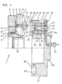
- the chuck shown in FIG. 1 and designated 1 has a plurality of base jaws 4, preferably three evenly displaceable uniformly over the circumference of a chuck body 2 in radially directed grooves 3, which can be driven by a central adjusting member 5 via wedge bars 8.
- the wedge bars 8 inserted in tangentially directed recesses 7 of the chuck body 2 each have a keyway 9, into which the adjusting member 5 engages with molded lugs 6, and a toothing 10 with which a toothing 11 worked on the base jaws 4 is in engagement , Mistake.
- the keyways 9 and the lugs 6 are inclined in the axial direction, an axial displacement of the adjusting member 5 is deflected into a radial movement of the base jaws 4.
- top jaws 21 To easily add top jaws 21 To be able to fit onto the base jaws 4, a mushroom-like extension 12 is formed thereon, which is provided with an undercut 13, and the top clamping jaws 21 have a recess 25 receiving the extension 12, which is also equipped with an undercut 26.
- the cylindrical projection 12 thus engages behind the undercut 26 when the top jaws 21 are placed on the base jaws 4, so that they are securely supported on a crescent-shaped surface.
- a pallet 31 is provided in which the top jaws 21 are held.
- the pallet 31 is provided with radially directed recesses 32 arranged in accordance with the division of the base jaws 4 of the chuck 1, in which the top clamping jaws 21 act by means of clamping bolts 33 acting axially perpendicular to them, which, according to the embodiments of FIGS.
- clamping jaws 21 are centered in the large-sized recesses 32 by means of the clamping bolts 33 or 33 'or 33 ", which engage in the recesses 23 or 23" in the side surfaces 22 of the top clamping jaws 21 .
- the clamping bolts 33, 33 ', 33 " each acted upon by a compressive force, are arranged to be displaceable to a limited extent in the direction of the top clamping jaws 21, and the joint bearing on these is only possible in a defined position.
- the clamping bolts 33, 33 ' with a stop surface 39, 39' formed by a molded collar 38 or an adjusting piston 42, as well as bearing surfaces created by its conically shaped tips 40, 40 ', which interact with counter surfaces 37 or the top jaws 21.
- the distance between the stop surfaces 39, 39 'and the system on the top clamping jaws 21 is selected such that in the end position of the clamping bolts 33, 33' the top clamping jaws 21 are held centrally in the recesses 23.
- the clamping bolts 33, 33 ', 33 are each inserted into bushings 35 which are screwed into the threaded bores 34 machined into the pallet 31 and which are provided with stepped receiving bores 36. This not only forms the counter surfaces 37, but their position can also be easily changed if necessary will.
- the clamping bolts 33 are acted upon by the force of a compression spring 41 which is supported on the pallet 31.
- an adjusting piston 42 which can be acted upon by pressure medium, can also be provided on the clamping bolts 33 'in order to be able to clamp the top clamping jaws 21.
- a seal 43 is to be inserted into the molded collar and the pressure space 44 thus created is to be supplied with pressure medium via channels 45 which are to be connected to a pressure medium source by means of a connecting nipple 46.
- the clamping bolts 33 ' are slightly pretensioned by a spring 47, so that clamping is possible even without pressure medium supply.
- the ends 40 "of the clamping bolts 33" are cylindrical and engage in the recesses 23 "of the top clamping jaws 21 which are designed as cylindrical bores.
- the clamping bolts 33" are with a Adjustment pistons 42 "which can be acted upon by pressure medium are equipped on both sides, to which the pressure chambers 44 and 44" are assigned and to which the pressure medium supply channels 45 and 45 "are connected.
- the contact surfaces 49 interacting with the clamping jaws 21 are each attached to the clamping bolt 33" by one Bund 48 formed.
- the chuck 1 If the chuck 1 is to be fitted with the top jaws 21 held in the pallet 31, it must be adjusted to the left such that the lugs 12 worked on the base jaws 4 are inserted into the recesses 25 of the top jaws 21.
- the top jaws 21 equipped with an insertion bevel 24 also partially engage in the grooves 3 of the chuck body 2 so that they are thus guided laterally. During this feed movement, the locking pins 16 of a spring catch 15, each inserted in a bore 14 of the base jaws 4, are pressed inward against the force of a spring 17.
- the base jaws 4 are shifted inwards with the aid of the adjusting member 5, so that the lugs 12 snap into the undercuts 26 and the top jaws 21 thus because the locking pin 16 the spring catch 15 is pressed into a receiving bore 30 machined into the top jaws 21 by the force of the spring 17, are securely locked to the base jaws 4.
- the pallet 31 can be detached from the top jaws 21 by an axial movement.
- the top jaws 21 can be placed on the base jaws 4 and removed with the aid of the pallet 31 by machine in a short time without difficulty and without canting occurring in the sufficiently wide recesses 32.
- the top clamping jaws 21 are each composed of a cassette 27 and a clamping insert 28, which are connected to one another by means of screws 29.
- the clamping inserts 28 which can also be attached to the outer end faces of the cassette 27, top jaws for workpieces with different diameters can thus be created without further ado.
- the unlocking bolts 51 are screwed into threaded bores 52 of the pallet 31 by means of threaded attachments 53 and equipped with a collar 54 designed as a polygon, which is arranged as an insert in the recesses 32. Due to the height of the collar 54, against which the top jaws 21 lie flat, different heights of the top jaws can thus be compensated by exchanging the unlocking bolts 51.
- an axially projecting collar 55 is furthermore worked on on the end face opposite the recesses 32, on which the delivery device 56 can engage. If the collar 55 is dimensioned approximately the same size as the workpieces to be clamped by means of the top jaws inserted in a pallet 31, no change is to be made when they are fed in by means of the feed device 56.
- the pallet 31 can also be transported by means of other adjusting elements which engage in receiving bores 57 provided with undercuts 58 and arranged between the recesses 32.
Landscapes
- Engineering & Computer Science (AREA)
- Mechanical Engineering (AREA)
- Jigs For Machine Tools (AREA)
- Gripping On Spindles (AREA)
Applications Claiming Priority (2)
| Application Number | Priority Date | Filing Date | Title |
|---|---|---|---|
| DE19833345012 DE3345012A1 (de) | 1983-12-13 | 1983-12-13 | Palette zur aufnahme von aufsatzspannbacken |
| DE3345012 | 1983-12-13 |
Publications (3)
| Publication Number | Publication Date |
|---|---|
| EP0145860A2 EP0145860A2 (de) | 1985-06-26 |
| EP0145860A3 EP0145860A3 (en) | 1986-07-30 |
| EP0145860B1 true EP0145860B1 (de) | 1988-04-20 |
Family
ID=6216799
Family Applications (1)
| Application Number | Title | Priority Date | Filing Date |
|---|---|---|---|
| EP84111268A Expired EP0145860B1 (de) | 1983-12-13 | 1984-09-21 | Palette zur Aufnahme von Aufsatzspannbacken |
Country Status (4)
| Country | Link |
|---|---|
| US (1) | US4641414A (https=) |
| EP (1) | EP0145860B1 (https=) |
| JP (1) | JPS60141410A (https=) |
| DE (2) | DE3345012A1 (https=) |
Families Citing this family (8)
| Publication number | Priority date | Publication date | Assignee | Title |
|---|---|---|---|---|
| JPS61103710A (ja) * | 1984-10-24 | 1986-05-22 | Toyoda Autom Loom Works Ltd | 旋盤用チヤツク爪の自動交換方法及び交換治具 |
| DE3533078C1 (de) * | 1985-09-17 | 1987-02-19 | Gildemeister Ag | Spannbackenwechselvorrichtung |
| US4722536A (en) * | 1986-02-07 | 1988-02-02 | Logansport Machine Co., Inc. | Quick change chuck jaw |
| JP3055924B2 (ja) * | 1990-09-04 | 2000-06-26 | ヤマザキマザック株式会社 | 生産システム |
| DE10203667A1 (de) * | 2002-01-30 | 2003-07-31 | Roehm Gmbh | Kraftbetätigtes Spannfutter |
| DE102005031142A1 (de) * | 2005-07-04 | 2007-01-18 | Forkardt Deutschland Gmbh | Spannvorrichtung, Grundbacken und Aufsatzbacken dafür |
| JP7087505B2 (ja) * | 2018-03-19 | 2022-06-21 | 豊和工業株式会社 | チャックの爪交換用ハンド、チャックの爪自動交換方法及び爪自動交換システム |
| US11992885B2 (en) * | 2018-10-30 | 2024-05-28 | Howa Machinery, Ltd. | Chuck-claw guide structure and chuck-claw insertion method |
Family Cites Families (10)
| Publication number | Priority date | Publication date | Assignee | Title |
|---|---|---|---|---|
| GB150669A (en) * | 1919-08-29 | 1921-06-16 | David Friedmann | Improvements in chucks |
| US3344511A (en) * | 1965-02-08 | 1967-10-03 | Giddings & Lewis | Toolholder and gripping device for automatic tool changers |
| DE2104904C3 (de) * | 1971-02-03 | 1974-04-11 | Werkzeugmaschinenfabrik Gildemeister & Co Ag, 4800 Bielefeld | Spannvorrichtung für Drehmaschinen u.dgl. Werkzeugmaschinen mit Schnellwechsel der Aufsatzspannbacken |
| DE2248403B2 (de) * | 1972-10-03 | 1975-05-15 | Paul Forkardt Kg, 4000 Duesseldorf | Spannfutter |
| DE2509698A1 (de) * | 1975-03-06 | 1976-09-09 | Austermann Heinz | Distanzstueck |
| DE2805828A1 (de) * | 1978-02-11 | 1979-08-16 | Heyligenstaedt & Co | Drehmaschine mit automatischem spannbackenwechsel |
| DE2849188C2 (de) * | 1978-11-13 | 1986-03-27 | Gildemeister Ag, 4800 Bielefeld | Einrichtung zum automatischen Wechseln von Spannbacken des Spannfutters einer Werkzeugmaschine |
| US4399603A (en) * | 1980-11-17 | 1983-08-23 | Giddings & Lewis, Inc. | Power grip tool exchange arm for machining center |
| JPS58102605A (ja) * | 1981-12-05 | 1983-06-18 | Yamazaki Mazak Corp | チヤツク爪自動交換装置 |
| JPS5973210A (ja) * | 1983-03-28 | 1984-04-25 | Howa Mach Ltd | チャック爪自動交換装置 |
-
1983
- 1983-12-13 DE DE19833345012 patent/DE3345012A1/de not_active Withdrawn
-
1984
- 1984-09-21 DE DE8484111268T patent/DE3470472D1/de not_active Expired
- 1984-09-21 EP EP84111268A patent/EP0145860B1/de not_active Expired
- 1984-12-10 US US06/679,759 patent/US4641414A/en not_active Expired - Fee Related
- 1984-12-11 JP JP59260102A patent/JPS60141410A/ja active Granted
Also Published As
| Publication number | Publication date |
|---|---|
| EP0145860A3 (en) | 1986-07-30 |
| US4641414A (en) | 1987-02-10 |
| DE3470472D1 (en) | 1988-05-26 |
| JPH0123243B2 (https=) | 1989-05-01 |
| DE3345012A1 (de) | 1985-06-20 |
| JPS60141410A (ja) | 1985-07-26 |
| EP0145860A2 (de) | 1985-06-26 |
Similar Documents
| Publication | Publication Date | Title |
|---|---|---|
| EP2134490B1 (de) | Werkzeughalter | |
| CH687599A5 (de) | Spannvorrichtung zum Spannen einer Aufspannplatte auf einer Traegerplatte fuer Bearbeitungsmaschinen. | |
| DE102010047380B3 (de) | Linearer mechanischer Schnellverschluß | |
| EP0742081A2 (de) | Universal-Präzisionsschraubstock für eine Werkzeugmaschine | |
| DE102005031142A1 (de) | Spannvorrichtung, Grundbacken und Aufsatzbacken dafür | |
| DE3937570C2 (https=) | ||
| WO2013037458A1 (de) | Spannsystem sowie grundkörper, spannzange und rotationswerkzeug dafür und ein installationsverfahren für das rotationswerkzeug im spannsystem | |
| DE3835879C1 (https=) | ||
| EP0145860B1 (de) | Palette zur Aufnahme von Aufsatzspannbacken | |
| EP0287777B1 (de) | Vorrichtung zur Halterung von Werkzeugen oder Werkstücken, die einen Zylindrischen Schaft aufweisen | |
| EP0085782B1 (de) | Spannfutter | |
| DE3808210C2 (https=) | ||
| EP4194142B1 (de) | Basiseinheit zum lösbaren fixieren von werkstückträgern | |
| EP0247410A2 (de) | Kupplung zur Verbindung von Werkzeugkopf und Werkzeughalter an Werkzeugmaschinen | |
| EP0189528B1 (de) | Spannfutter für Werkzeugmaschinen | |
| DE202004018168U1 (de) | Aus einer Spannvorrichtung und einem Werkstückträger gebildete Einheit | |
| DE3822473A1 (de) | Vorrichtung zum kuppeln und entkuppeln von greiferschienenteilen | |
| EP0178417B1 (de) | Teilbares Werkzeug für die spanabhebende Bearbeitung | |
| DE8335731U1 (de) | Palette zur Aufnahme von Aufsatzspannbacken | |
| EP0900628B1 (de) | Schnell-Pass-System | |
| DE19919408A1 (de) | Membranspannfutter | |
| EP0421069A1 (de) | Ausrichtevorrichtung | |
| WO1993009902A1 (de) | Spannvorrichtung zur verbindung von werkzeugkopf und werkzeughalter an werkzeugmaschinen | |
| EP0121665A2 (de) | Vorrichtung zum Einspannen von Wechselkassetten | |
| DE3700841A1 (de) | Kupplungselement, insbesondere zum kraft- und formschluessigen verbinden eines werkzeugkopfes mit einem werkzeugtraeger |
Legal Events
| Date | Code | Title | Description |
|---|---|---|---|
| PUAI | Public reference made under article 153(3) epc to a published international application that has entered the european phase |
Free format text: ORIGINAL CODE: 0009012 |
|
| AK | Designated contracting states |
Designated state(s): DE FR GB IT SE |
|
| 17P | Request for examination filed |
Effective date: 19850510 |
|
| PUAL | Search report despatched |
Free format text: ORIGINAL CODE: 0009013 |
|
| AK | Designated contracting states |
Kind code of ref document: A3 Designated state(s): DE FR GB IT SE |
|
| 17Q | First examination report despatched |
Effective date: 19861023 |
|
| GRAA | (expected) grant |
Free format text: ORIGINAL CODE: 0009210 |
|
| AK | Designated contracting states |
Kind code of ref document: B1 Designated state(s): DE FR GB IT SE |
|
| PG25 | Lapsed in a contracting state [announced via postgrant information from national office to epo] |
Ref country code: SE Effective date: 19880430 |
|
| REF | Corresponds to: |
Ref document number: 3470472 Country of ref document: DE Date of ref document: 19880526 |
|
| ITF | It: translation for a ep patent filed | ||
| GBT | Gb: translation of ep patent filed (gb section 77(6)(a)/1977) | ||
| ET | Fr: translation filed | ||
| PLBE | No opposition filed within time limit |
Free format text: ORIGINAL CODE: 0009261 |
|
| STAA | Information on the status of an ep patent application or granted ep patent |
Free format text: STATUS: NO OPPOSITION FILED WITHIN TIME LIMIT |
|
| 26N | No opposition filed | ||
| ITTA | It: last paid annual fee | ||
| PGFP | Annual fee paid to national office [announced via postgrant information from national office to epo] |
Ref country code: GB Payment date: 19920911 Year of fee payment: 9 |
|
| PGFP | Annual fee paid to national office [announced via postgrant information from national office to epo] |
Ref country code: FR Payment date: 19920916 Year of fee payment: 9 |
|
| PG25 | Lapsed in a contracting state [announced via postgrant information from national office to epo] |
Ref country code: GB Effective date: 19930921 |
|
| PGFP | Annual fee paid to national office [announced via postgrant information from national office to epo] |
Ref country code: DE Payment date: 19931125 Year of fee payment: 10 |
|
| GBPC | Gb: european patent ceased through non-payment of renewal fee |
Effective date: 19930921 |
|
| PG25 | Lapsed in a contracting state [announced via postgrant information from national office to epo] |
Ref country code: FR Free format text: LAPSE BECAUSE OF NON-PAYMENT OF DUE FEES Effective date: 19940531 |
|
| REG | Reference to a national code |
Ref country code: FR Ref legal event code: ST |
|
| PG25 | Lapsed in a contracting state [announced via postgrant information from national office to epo] |
Ref country code: DE Effective date: 19950601 |