EP0145465A2 - Floating-point addition/subtraction system - Google Patents
Floating-point addition/subtraction system Download PDFInfo
- Publication number
- EP0145465A2 EP0145465A2 EP84308518A EP84308518A EP0145465A2 EP 0145465 A2 EP0145465 A2 EP 0145465A2 EP 84308518 A EP84308518 A EP 84308518A EP 84308518 A EP84308518 A EP 84308518A EP 0145465 A2 EP0145465 A2 EP 0145465A2
- Authority
- EP
- European Patent Office
- Prior art keywords
- shifting
- data
- control data
- sets
- shifting control
- Prior art date
- Legal status (The legal status is an assumption and is not a legal conclusion. Google has not performed a legal analysis and makes no representation as to the accuracy of the status listed.)
- Granted
Links
Images


Classifications
-
- G—PHYSICS
- G06—COMPUTING; CALCULATING OR COUNTING
- G06F—ELECTRIC DIGITAL DATA PROCESSING
- G06F7/00—Methods or arrangements for processing data by operating upon the order or content of the data handled
-
- G—PHYSICS
- G06—COMPUTING; CALCULATING OR COUNTING
- G06F—ELECTRIC DIGITAL DATA PROCESSING
- G06F7/00—Methods or arrangements for processing data by operating upon the order or content of the data handled
- G06F7/38—Methods or arrangements for performing computations using exclusively denominational number representation, e.g. using binary, ternary, decimal representation
- G06F7/48—Methods or arrangements for performing computations using exclusively denominational number representation, e.g. using binary, ternary, decimal representation using non-contact-making devices, e.g. tube, solid state device; using unspecified devices
- G06F7/483—Computations with numbers represented by a non-linear combination of denominational numbers, e.g. rational numbers, logarithmic number system or floating-point numbers
- G06F7/485—Adding; Subtracting
-
- G—PHYSICS
- G06—COMPUTING; CALCULATING OR COUNTING
- G06F—ELECTRIC DIGITAL DATA PROCESSING
- G06F7/00—Methods or arrangements for processing data by operating upon the order or content of the data handled
- G06F7/38—Methods or arrangements for performing computations using exclusively denominational number representation, e.g. using binary, ternary, decimal representation
- G06F7/48—Methods or arrangements for performing computations using exclusively denominational number representation, e.g. using binary, ternary, decimal representation using non-contact-making devices, e.g. tube, solid state device; using unspecified devices
- G06F7/50—Adding; Subtracting
-
- G—PHYSICS
- G06—COMPUTING; CALCULATING OR COUNTING
- G06F—ELECTRIC DIGITAL DATA PROCESSING
- G06F7/00—Methods or arrangements for processing data by operating upon the order or content of the data handled
- G06F7/38—Methods or arrangements for performing computations using exclusively denominational number representation, e.g. using binary, ternary, decimal representation
- G06F7/48—Methods or arrangements for performing computations using exclusively denominational number representation, e.g. using binary, ternary, decimal representation using non-contact-making devices, e.g. tube, solid state device; using unspecified devices
- G06F7/499—Denomination or exception handling, e.g. rounding or overflow
- G06F7/49905—Exception handling
-
- G—PHYSICS
- G06—COMPUTING; CALCULATING OR COUNTING
- G06F—ELECTRIC DIGITAL DATA PROCESSING
- G06F7/00—Methods or arrangements for processing data by operating upon the order or content of the data handled
- G06F7/38—Methods or arrangements for performing computations using exclusively denominational number representation, e.g. using binary, ternary, decimal representation
- G06F7/48—Methods or arrangements for performing computations using exclusively denominational number representation, e.g. using binary, ternary, decimal representation using non-contact-making devices, e.g. tube, solid state device; using unspecified devices
- G06F7/499—Denomination or exception handling, e.g. rounding or overflow
- G06F7/49936—Normalisation mentioned as feature only
Definitions
- the present invention relates to a system of floating-point addition/subtraction for two sets of data.
- a system according to the present invention may be applied in computers for general-purpose work.
- realization of the digit position alignment of fractions, addition of fractions, and normalization are carried out in the addition/subtraction of two sets of data each .consisting of a sign portion, a characteristic (exponent) portion, and a fraction (mantissa) portion.
- a comparison calculation of the characteristic of two sets of input data is carried out in a comparator to generate shift control data representing the difference between the characteristics and information telling which set of input data is greater than the other set of input data.
- the generated shift control data is then supplied to shifting circuits in which the shifting operation of the fractions is carried out for realizing the digit position alignment between the fractions of the two sets of input data.
- An embodiment of the present invention can provide an improved system of floating-point addition/subtraction for two sets of data in which shifting of the fractions of the two sets of data, and accordingly, addition/subtraction between the two sets of data, is carried out at a high speed.
- a system of floating-point addition/subtraction for two sets of data in which a comparison calculation between the characteristics of the two sets of data is carried out to generate .
- shifting control data for realizing digit position alignment between the fractions of the two sets of data and a shifting operation is carried out on the basis of the generated shifting control data.
- the system includes a first shifting control data generating unit for generating shifting control data based on a comparison between lower bits of the characteristics of the two sets of data; and a second shifting control data generating unit for generating shifting control data based on a comparison between the entire bits of the characteristics of the two sets of data.
- the system also includes a first shifting unit for realizing digit position alignment between the fractions of the two sets of data based on the shifting control data generated by the first shifting control data generating unit; a second shifting unit for realizing digit position alignment between the fractions of the two sets of data based on the shifting control data generated by the second shifting control data generating unit; and a calculation unit for carrying out addition based on outputs from the second shifting unit.
- the digit position alignment between the fractions of the two sets of data is attained by carrying out the shifting control data generation in parallel with the shifting-operation.
- Fig. 1 the format of an example of the floating-point representation is shown in Fig. 1, and a diagram of a known circuit for calculation by the floating-point representation system is shown in Fig. 2.
- the data expressed as +A x 16 E , consists of a sign (+) portion of 1 bit, a characteristic or exponent (E) portion of 7 bits, and a fraction or mantissa (A) portion of 7 bytes.
- the entire set of data consists of 8 bytes.
- the known circuit shown in Fig. 2 includes a comparator 100, No. 1 shifter 201, No. 2 shifter 202, and a carry propagate adder 300.
- the characteristics of the No. 1 set of input data and No. 2 set of input data are compared in the comparator to produce shifting control data representing the difference between the characteristics of the No. 1 and No. 2 sets of data and information telling which set of input data is the greater..-
- the produced shifting control data is supplied to the No. 1 shifter 201 and the No. 2 shifter 202 to cause a shifting operation for aligning the digit position of the fractions of the two sets of input data.
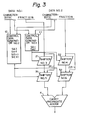
- Figure 3 shows a diagram of a circuit for calculation by the floating-point representation system in which a method is used according to an embodiment of the present invention.
- the circuit shown in Fig. 3 includes No. 1 control data generator 11 and No. 2 control data generator 12 for producing the shifting control data, No. 3 shifter 21, No. 4 shifter 22, No. 5 shifter 31, No. 6 shifter 32, and a carry propagate adder 4.
- SAl and SA2 are the shifting control data produced as the result (characteristics of the) of comparison between the lower position digits of the / two sets of input data.
- SA3, SA4, S(TH), and S(EX) are the shifting control data produced as the result of comparison between the upper position digits of the two sets of input data.
- SAl and SA2 are produced by a relatively low number of logic steps in a relatively short time, while SA3, SA4, S(TH), and S(EX) are produced by a relatively large number of logic steps in a relatively long time.
- the production of SA3, SA4, S(TH), and S(EX) is carried out in parallel with the shifting operation using SAl and SA2, in order to complete the entire operation of the shifting control in a short time.
- the fine shifting control data for 0, 1, 2, and 3 digit position shifting (0, 4, 8, and 12 bit shifting) and the rough shifting control data for 0, 4, 8, and 12 digit position shifting (0, 16, 32, 48 bit shifting) are produced. Any part of the 0 digit position to 15 digit position shifting is carried out by combining the above-described fine and rough shifting control data. Thus, any part of the shifting control data is represented by 2 bits.
- S(TH) is the "through" signal which prevents the shifting from being carried out for the fraction of the input data in question having a characteristic which is greater than the characteristic of the other input data. If a calculation is to be made between two sets of input data, the fraction of one input data having the characteristic which is smaller than the characteristic of the other input data should be shifted right, while the fraction of the other input data having the characteristic which is larger than the above-mentioned one input data should be prevented from being shifted.
- S(EX) is the "exceed" signal which indicates a shifting of digit positions exceeding 15 digit positions, that is 16 digit positions or more, and accordingly, gives an instruction that the entire bits (every bit) of the fraction be-changed to zero.
- the through signal S(TH) is "0"
- the shifter 32 is controlled in such the manner that the by-pass 221 is selected and the fraction of DATA No. 2 passes through without being shifted.
- the through signal S(TH) is "1”
- the shifter 31 is that controlled in such a manner/the by-pass 211 is selected and . the fraction of DATA No. 1 passes through without being shifted.
- the circuit shown in Fig. 3 is operated as follows.
- the shifting control signals SAl and SA2 for the fine shifting of 0, 1, 2, or 3 digit positions, derived from the lower bits of the characteristics of DATA No. 1 and DATA No. 2, are calculated in the control data generator 11.
- the time required for the calculation of the shift amount is relatively short.
- the shifting control signals SAl and SA2 are generated in a relatively short time.
- the generated SAl and SA2 are immediately supplied to the shifter 21 and the shifter 22 to carry out the fine shifting operation.
- the remainder shifting control signals SA3, SA4 for the rough shifting of 0, 4, 8, or 12 digit position, S(TH), and S(EX), derived from the entire bits of the characteristics of DATA No. 1 and DATA No. 2, are calculated in the control data generator 12.
- the generated SA3, SA4, S(TH), and S(EX) are supplied to the shifter 31 and the shifter 32 to carry out the rough shifting operation.
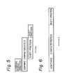
- FIG. 5 A time chart of the operation in the circuit shown in Fig. 3 is shown in Fig. 5.
- FIG. 6 A time chart of the operation in the corresponding prior art circuit of Fig. 2 is shown in Fig. 6. It will be seen from a comparison between Fig. 5 and Fig. 6 that the entire operation of the digit position alignment of the fractions of two sets of data can be carried out in the case of the circuit shown in Fig. 5 in a shorter time than in the case of the circuit shown in Fig. 6.
- FIG. 7 A modified embodiment of the present invention is shown in Fig. 7.
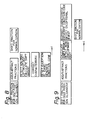
- the time chart of the operation in the circuit shown in Fig. 7 is shown in Fig. 8.
- the circuit shown in Fig. 7 includes a control data generator 11, a control data generator 12, shifters 21, 22, 31, and 32, a carry propagate adder 4, and a carry look ahead portion 41.
- the circuit shown in Fig. 7 also (leftmost) includes a selector 13, a non-zero /digit detection and shift amount calculation portion 5, an exceptional event detection and condition code generation portion 6, a characteristic correction portion 7, and a shifter 8.
- the non-zero leftmost digit detection and shift amount calculation portion 5 detects non-zero leftmost digits in a result of the addition/subtraction in parallel with the algebraic addition/subtraction treatment carried out in the carry look ahead portion 41 by the time the result of the algebraic addition/ subtraction treatment is obtained, and calculates the shift amount necessary for the normalization of the non-zero leftmost digits.
- the non-zero digit detection and shift amount calculation portion see Japanese Patent Application No. 58-103152. (non-zero ettmost)
- the exceptional event detection and condition code generation portion 6 receives the data from the non-zero leftmost digit detection and shift amount calculation portion 5 and the selector 13 to generate an exceptional event detection and condition code.
- the shifter 8 receives the data from the carry propagate adder and the non-zero leftmost digit detection and shift amount calculation portion 5 and carries out a left shifting of the non-zero leftmost digit in the fraction based on the shift amount for the normalization. This shifting is called post-calculation normalization or post-shifting.
- the characteristic correction portion 7 subtracts the left shift amount necessary for the normalization obtained in the non-zero leftmost digit detection and shift amount calculation portion 5 from the characteristic of one of the input DATA Nos. 1 and 2 which has a characteristic greater than the characteristic of the other input DATA, so that the characteristic of the final output data is generated.
- the exceptional event detection and condition code generation portion 6 generates the condition code interruption signal with reference to the interruption mask condition and the like.
- the exceptional event detection and condition code generation portion 6 can be operated in parallel with the operation of the characteristic correction portion 7.
- FIG. 8 A time chart of the operation in the circuit shown in Fig. 7 is shown in Fig. 8.
- FIG. 9 A time chart of the operation in the corresponding prior art circuit is shown in Fig. 9. It will be seen from the comparison between Fig. 8 and Fig. 9 that the entire addition/ subtraction operation can be carried out in the case of the circuit shown in Fig. 7 in a shorter time than in the corresponding prior art case.
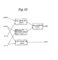
- FIG. 10 and Fig. 11 An example of a circuit for generating the signals SA1, SA2, SA3, SA4, S(EX), and S(TH) used for the circuits shown in Fig. 3 and Fig. 7 is shown in Fig. 10 and Fig. 11.
- E 1 is the characteristic of DATA No. 1 and consists of 7 bits as follows.
- E l e(1, 7), e(l, 6), e(l, 5), e(l, 4), e(l, 3), e(l, 2), e(l, 1)
- E 2 is the characteristic of DATA No. 2 and consists of 7 bits as follows.
- SA1 relates to the lowest bit of "E 2 -E 1 ".
- SA2 relates to the second bit from the lowest bit of "E 2 -E 1 ".
- SA3 relates to the third bit from the lowest bit of "E 2 -E 1 ".
- SA4 relates to the fourth bit from the lowest bit of "E 2 -E l “.
- S(TH) relates to the condition "E 2 -E 1 ⁇ -1”.
- S(EX) relates to the condition "E 2 -E 1 ⁇ -16" or "E 2 -E 1 ⁇ 16", that is
Abstract
Description
- The present invention relates to a system of floating-point addition/subtraction for two sets of data. A system according to the present invention may be applied in computers for general-purpose work.
- In general, realization of the digit position alignment of fractions, addition of fractions, and normalization,are carried out in the addition/subtraction of two sets of data each .consisting of a sign portion, a characteristic (exponent) portion, and a fraction (mantissa) portion.
- In a known process, first, a comparison calculation of the characteristic of two sets of input data is carried out in a comparator to generate shift control data representing the difference between the characteristics and information telling which set of input data is greater than the other set of input data. The generated shift control data is then supplied to shifting circuits in which the shifting operation of the fractions is carried out for realizing the digit position alignment between the fractions of the two sets of input data.
- In such a known process, the comparison calculation of the characteristics and the shifting operation of the fractions are carried out only in sequence. Thus, there has been a problem in such a process in that it takes a considerable length of time to carry out the processing of floating-point addition/subtraction for two sets of data.
- An embodiment of the present invention can provide an improved system of floating-point addition/subtraction for two sets of data in which shifting of the fractions of the two sets of data, and accordingly, addition/subtraction between the two sets of data, is carried out at a high speed.
- According to the present invention, there is provided a system of floating-point addition/subtraction for two sets of data in which a comparison calculation between the characteristics of the two sets of data is carried out to generate . shifting control data for realizing digit position alignment between the fractions of the two sets of data and a shifting operation is carried out on the basis of the generated shifting control data. The system includes a first shifting control data generating unit for generating shifting control data based on a comparison between lower bits of the characteristics of the two sets of data; and a second shifting control data generating unit for generating shifting control data based on a comparison between the entire bits of the characteristics of the two sets of data. The system also includes a first shifting unit for realizing digit position alignment between the fractions of the two sets of data based on the shifting control data generated by the first shifting control data generating unit; a second shifting unit for realizing digit position alignment between the fractions of the two sets of data based on the shifting control data generated by the second shifting control data generating unit; and a calculation unit for carrying out addition based on outputs from the second shifting unit. In the system, the digit position alignment between the fractions of the two sets of data is attained by carrying out the shifting control data generation in parallel with the shifting-operation.
- Reference is made, by way of example, to the accompanying drawings in which:-
- Fig. 1 shows the format of an example of the floating-point representation;
- Fig. 2 is a diagram of a known circuit for floating-point calculation;
- Fig. 3 is a diagram of a circuit for calculation according to an embodiment of the present invention; .
- Fig. 4 is a table giving an example of shifting control data used in the circuit shown in Fig. 3;
- Fig. 5 illustrates the manner of operation of the circuit shown in Fig. 3;
- Fig. 6 illustrates the manner of operation of the known , circuit shown in Fig. 2;
- Fig. 7 shows a modified embodiment of the present invention;
- Fig. 8 illustrates the manner of operation of the embodiment shown in Fig. 7;
- Fig. 9 illustrates a known manner of operation corresponding to the operation illustrated in Fig. 8; and
- Figs. 10 and 11 show examples of a circuit for generating shifting control data used for the circuits shown in Fig. 3 and Fig. 7.
- To further assist with the understanding of the preferred embodiments, the format of an example of the floating-point representation is shown in Fig. 1, and a diagram of a known circuit for calculation by the floating-point representation system is shown in Fig. 2.
- In the example shown in Fig. 1, the data, expressed as +A x 16E, consists of a sign (+) portion of 1 bit, a characteristic or exponent (E) portion of 7 bits, and a fraction or mantissa (A) portion of 7 bytes. Thus, the entire set of data consists of 8 bytes.
- The known circuit shown in Fig. 2 includes a
comparator 100, No. 1 shifter 201, No. 2 shifter 202, and acarry propagate adder 300. The characteristics of the No. 1 set of input data and No. 2 set of input data are compared in the comparator to produce shifting control data representing the difference between the characteristics of the No. 1 and No. 2 sets of data and information telling which set of input data is the greater..- The produced shifting control data is supplied to the No. 1 shifter 201 and the No. 2 shifter 202 to cause a shifting operation for aligning the digit position of the fractions of the two sets of input data. - Figure 3 shows a diagram of a circuit for calculation by the floating-point representation system in which a method is used according to an embodiment of the present invention. The circuit shown in Fig. 3 includes No. 1
control data generator 11 and No. 2control data generator 12 for producing the shifting control data, No. 3shifter 21, No. 4shifter 22, No. 5shifter 31, No. 6shifter 32, and acarry propagate adder 4. - The combinations of the shifting control data S(TH), S(EX), SA4, SA3, SA2, and SAl corresponding to the combinations of the No. 1 set of input data and the No. 2 set of input data are listed in Fig. 4. SAl and SA2 are the shifting control data produced as the result (characteristics of the) of comparison between the lower position digits of the / two sets of input data. SA3, SA4, S(TH), and S(EX) are the shifting control data produced as the result of comparison between the upper position digits of the two sets of input data. SAl and SA2 are produced by a relatively low number of logic steps in a relatively short time, while SA3, SA4, S(TH), and S(EX) are produced by a relatively large number of logic steps in a relatively long time. In this embodiment of the.present invention, the production of SA3, SA4, S(TH), and S(EX) is carried out in parallel with the shifting operation using SAl and SA2, in order to complete the entire operation of the shifting control in a short time.
- For carrying out 0 digit position to 15 digit position shifting, the fine shifting control data for 0, 1, 2, and 3 digit position shifting (0, 4, 8, and 12 bit shifting) and the rough shifting control data for 0, 4, 8, and 12 digit position shifting (0, 16, 32, 48 bit shifting) are produced. Any part of the 0 digit position to 15 digit position shifting is carried out by combining the above-described fine and rough shifting control data. Thus, any part of the shifting control data is represented by 2 bits.
- S(TH) is the "through" signal which prevents the shifting from being carried out for the fraction of the input data in question having a characteristic which is greater than the characteristic of the other input data. If a calculation is to be made between two sets of input data, the fraction of one input data having the characteristic which is smaller than the characteristic of the other input data should be shifted right, while the fraction of the other input data having the characteristic which is larger than the above-mentioned one input data should be prevented from being shifted.
- S(EX) is the "exceed" signal which indicates a shifting of digit positions exceeding 15 digit positions, that is 16 digit positions or more, and accordingly, gives an instruction that the entire bits (every bit) of the fraction be-changed to zero.
- Hence, 1 bit is necessary for S(TH) and another 1 bit is necessary for S(EX). Accordingly, 6 bits are necessary for SA1, SA2, SA3, SA4, S(TH), and S(EX).
- When the characteristic of DATA No. 1 is smaller than the characteristic of DATA No. 2, the through signal S(TH) is "0", and the
shifter 32 is controlled in such the manner that the by-pass 221 is selected and the fraction of DATA No. 2 passes through without being shifted. Conversely, when the characteristic of DATA No. 1 is greater than the characteristic of DATA No. 2, the through signal S(TH) is "1", and theshifter 31 is that controlled in such a manner/the by-pass 211 is selected and . the fraction of DATA No. 1 passes through without being shifted. - When the exceed signal S(EX) is "1", the fraction of the data to be shifted is controlled to become all "0".
- When SA1, SA2, SA3, and SA4 are all "1", a 15 digit position shifting of the fraction is carried out to cause the fraction of the data to be shifted to become all "0".
- The circuit shown in Fig. 3 is operated as follows. The shifting control signals SAl and SA2 for the fine shifting of 0, 1, 2, or 3 digit positions, derived from the lower bits of the characteristics of DATA No. 1 and DATA No. 2, are calculated in the
control data generator 11. The time required for the calculation of the shift amount is relatively short. Hence, the shifting control signals SAl and SA2 are generated in a relatively short time. The generated SAl and SA2 are immediately supplied to theshifter 21 and theshifter 22 to carry out the fine shifting operation. - During the fine shifting operation, the remainder shifting control signals SA3, SA4 for the rough shifting of 0, 4, 8, or 12 digit position, S(TH), and S(EX), derived from the entire bits of the characteristics of DATA No. 1 and DATA No. 2, are calculated in the
control data generator 12. The generated SA3, SA4, S(TH), and S(EX) are supplied to theshifter 31 and theshifter 32 to carry out the rough shifting operation. - When the "through" signal S(TH) is generated from the
control data generator 12 and is supplied to theshifters pass 211 and the by-pass 221 are selected by theshifter 31 and theshifter 32, irrespective of the fact that the shifting operations by SAl-and SA2 have been carried out in the shifter No. 3 and the shifter No. 4. - Hence, the operation of the generation of the shifting control data in the
control data generator 12 for SA3, SA4, S(TH), and S(EX) is carried out in parallel with the shifting operation in theshifters carry propagate adder 4 is obtained in a relatively short time. - A time chart of the operation in the circuit shown in Fig. 3 is shown in Fig. 5. A time chart of the operation in the corresponding prior art circuit of Fig. 2 is shown in Fig. 6. It will be seen from a comparison between Fig. 5 and Fig. 6 that the entire operation of the digit position alignment of the fractions of two sets of data can be carried out in the case of the circuit shown in Fig. 5 in a shorter time than in the case of the circuit shown in Fig. 6.
- A modified embodiment of the present invention is shown in Fig. 7. The time chart of the operation in the circuit shown in Fig. 7 is shown in Fig. 8.
- The circuit shown in Fig. 7 includes a
control data generator 11, acontrol data generator 12,shifters carry propagate adder 4, and a carry look aheadportion 41. The circuit shown in Fig. 7 also (leftmost) includes aselector 13, a non-zero /digit detection and shiftamount calculation portion 5, an exceptional event detection and conditioncode generation portion 6, acharacteristic correction portion 7, and ashifter 8. - The non-zero leftmost digit detection and shift
amount calculation portion 5 detects non-zero leftmost digits in a result of the addition/subtraction in parallel with the algebraic addition/subtraction treatment carried out in the carry look aheadportion 41 by the time the result of the algebraic addition/ subtraction treatment is obtained, and calculates the shift amount necessary for the normalization of the non-zero leftmost digits. With regard to the non-zero digit detection and shift amount calculation portion, see Japanese Patent Application No. 58-103152. (non-zero ettmost) - In the (invalid)/digit detection and shift
amount calculation portion 5, the detection of a non-zero leftmost digit in the upper digits of the intermediate sum and the calculation of the number n of digits of the normalization are carried out. - The exceptional event detection and condition
code generation portion 6 receives the data from the non-zero leftmost digit detection and shiftamount calculation portion 5 and theselector 13 to generate an exceptional event detection and condition code. - In the exceptional event detection and condition
code generation portion 6, detection of the following exceptional events is carried out. - (1) The result of calculation concerning the fractions is all "0".
- (2) An overflow of the characteristic occurs as the result of the normalization. For example, the characteristic goes from "63" to "64".
- (3) An underflow of the characteristic occurs as the result of the normalization. For example, the characteristic goes from "-64" to "-66".
- In the exceptional event detection and condition
code generation portion 6, generation of the following condition codes is carried out. - - (1) "Condition Code 0" is ON, when DATA No. 1 is equal to DATA No. 2.
- (2) "
Condition Code 1" is ON, when DATA No. 1 is smaller than DATA No. 2. - (3) "
Condition Code 2" is ON, when DATA No. 1 is greater than DATA No. 2. - The
shifter 8 receives the data from the carry propagate adder and the non-zero leftmost digit detection and shiftamount calculation portion 5 and carries out a left shifting of the non-zero leftmost digit in the fraction based on the shift amount for the normalization. This shifting is called post-calculation normalization or post-shifting. - The
characteristic correction portion 7 subtracts the left shift amount necessary for the normalization obtained in the non-zero leftmost digit detection and shiftamount calculation portion 5 from the characteristic of one of the input DATA Nos. 1 and 2 which has a characteristic greater than the characteristic of the other input DATA, so that the characteristic of the final output data is generated. - The exceptional event detection and condition
code generation portion 6 generates the condition code interruption signal with reference to the interruption mask condition and the like. The exceptional event detection and conditioncode generation portion 6 can be operated in parallel with the operation of thecharacteristic correction portion 7. - A time chart of the operation in the circuit shown in Fig. 7 is shown in Fig. 8. A time chart of the operation in the corresponding prior art circuit is shown in Fig. 9. It will be seen from the comparison between Fig. 8 and Fig. 9 that the entire addition/ subtraction operation can be carried out in the case of the circuit shown in Fig. 7 in a shorter time than in the corresponding prior art case.
- An example of a circuit for generating the signals SA1, SA2, SA3, SA4, S(EX), and S(TH) used for the circuits shown in Fig. 3 and Fig. 7 is shown in Fig. 10 and Fig. 11.
- E1 is the characteristic of DATA No. 1 and consists of 7 bits as follows.
- El: e(1, 7), e(l, 6), e(l, 5), e(l, 4), e(l, 3), e(l, 2), e(l, 1)
- E2 is the characteristic of DATA No. 2 and consists of 7 bits as follows.
- E2: e (2, 7), e (2, 6), e (2, 5), e (2, 4), e (2, 3), e(2, 2), e(2, 1)
- SA1 relates to the lowest bit of "E2-E1". SA2 relates to the second bit from the lowest bit of "E2-E1". SA3 relates to the third bit from the lowest bit of "E2-E1". SA4 relates to the fourth bit from the lowest bit of "E2-El". S(TH) relates to the condition "E2-E1≦-1". S(EX) relates to the condition "E2-E1≦-16" or "E2-E1≧16", that is |E2-E1|≧16.
- The logic equations of these signals are as follows, where "EOR" indicates an exclusive-OR logic operator.
- SAl: (e(2,1)=e(1,1))
- SA2: (e(2,2)≠e(1,2))EOR(e(2,1)<e(1,1))
- SA3: (e(2,3)≠e(1,3))EOR{(e(2,2)<e(1,2))+(e(2,2) ≦e(1,2)) (e(2,1)<e(1,1)}
- SA4 = (e(2,4)≠e(1,4))EOR{e(2,3)<e(1,3) +(e(2,3)≤e(1,3)) (e(2,2)<e(1,2)) +(e(2,3)≦e(1,3)) (e(2,2)≦e(1,2)) (e(2,1)<e(1,1))}
- S(EX) : (E1-E2≧16)+(E2-E1≧16)
- S(TH): (E2-E1≦-1)
- With regard to S(EX), (E1-E2≧16) is given as follows:
- (E1-E2≧16)=(e(1,7)>e(2,7))(e(1,6)≧e(2,6)) +(e(1,7)>e(2,7))(e(1,5)≧e(2,5))+(e(1,7)>e(2,7))(E1'≧E2') +(e(1,7)=e(2,7))(e(1,6)>e(2,6))(e(1,5)≧e(2,5)) +(e(1,7)=e(2,7))(e(1,6)>e(2,6))(E1'≧E2') +(e(1,7)=e(2,7))(e(1,6)=e(2,6))(e(1,5)>e(2,5))(E1'≧E2') where
- E1'≧E2'=(e(1,4)>e(2,4))+(e(1,4) ≧e(2,4))(e(1,3)>e(2,3))+(e(1,4)≧e(2,4))(e(1,3) ≧e(2,3)) (e(1,2)>e(2,2))+(e(1,4)≧e(2,4)) (e(1,3) ≧e(2,3))(e(1,2)≧e(2,2))(e(1,1)≧e(2,1))
- With regard to S(EX), (E2-E1≧16) is given similarly as in the case of (E1-E2≧16), except that numeral "1" is replaced by numeral "2" and numeral "2" is replaced by numeral "1".
- With regard to S(TH), (E2-E1≦-1) is given as follows:
- (E2-E1≦1)=(e(1,7)>e(2,7))+(e(1,7) ≧e(2,7))(e(1,6)>e(2,6))+(e(1,7)≧e(2,7))(e(1,6) ≧e(2,6))(e(1,5)>e(2,5))+(e(1,7)≧e(2,7))(e(1,6) ≧e(2,6)) (e(1,5)≧e(2.5)) (E1'>E2') where
- E1'>E2'=(e(1,4)>e(2,4))+(e(1,4)≧e(2,4))(e(1,3) >e(2,3))+(e(1,4)≧e(2,4))(e(1,3)≧e(2,3))(e(1,2)>e(2,2)) +(e(1,4)≧e(2,4))(e(1,3)≧e(2,3))(e(1,2) ≧e(2,2))(e(1,1)>e(2,1)).
Claims (5)
said second shifting is a rough shifting of the digit positions of the fraction of said one of said two sets of data, which together with said first shifting completely achieves digit position alignment between the fractions of said two sets of data.
Applications Claiming Priority (4)
| Application Number | Priority Date | Filing Date | Title |
|---|---|---|---|
| JP58233114A JPS60124729A (en) | 1983-12-09 | 1983-12-09 | Adding and subtracting system of floating point data |
| JP233114/83 | 1983-12-09 | ||
| JP248422/83 | 1983-12-29 | ||
| JP58248422A JPS60142736A (en) | 1983-12-29 | 1983-12-29 | Floating point adding and subtracting system |
Publications (3)
| Publication Number | Publication Date |
|---|---|
| EP0145465A2 true EP0145465A2 (en) | 1985-06-19 |
| EP0145465A3 EP0145465A3 (en) | 1986-05-28 |
| EP0145465B1 EP0145465B1 (en) | 1990-03-28 |
Family
ID=26530854
Family Applications (1)
| Application Number | Title | Priority Date | Filing Date |
|---|---|---|---|
| EP84308518A Expired - Lifetime EP0145465B1 (en) | 1983-12-09 | 1984-12-07 | Floating-point addition/subtraction system |
Country Status (8)
| Country | Link |
|---|---|
| US (1) | US5016209A (en) |
| EP (1) | EP0145465B1 (en) |
| KR (1) | KR890004307B1 (en) |
| AU (1) | AU555230B2 (en) |
| BR (1) | BR8406284A (en) |
| CA (1) | CA1229415A (en) |
| DE (1) | DE3481788D1 (en) |
| ES (1) | ES538377A0 (en) |
Cited By (5)
| Publication number | Priority date | Publication date | Assignee | Title |
|---|---|---|---|---|
| DE3236391A1 (en) * | 1982-10-01 | 1984-04-05 | Hans Joachim Dipl.-Ing. Eitel | Casting powder for cast steel |
| US4760550A (en) * | 1986-09-11 | 1988-07-26 | Amdahl Corporation | Saving cycles in floating point division |
| US4858165A (en) * | 1987-06-19 | 1989-08-15 | Digital Equipment Corporation | Apparatus and method for acceleration of effective subtraction procedures by the approximation of the absolute value of the exponent argument difference |
| EP0332215A2 (en) * | 1988-03-11 | 1989-09-13 | Fujitsu Limited | Operation circuit based on floating-point representation |
| EP0474247A2 (en) * | 1990-09-07 | 1992-03-11 | Nec Corporation | Shift amount floating-point calculating circuit with a small amount of hardware and rapidly operable |
Families Citing this family (5)
| Publication number | Priority date | Publication date | Assignee | Title |
|---|---|---|---|---|
| US5247471A (en) * | 1991-12-13 | 1993-09-21 | International Business Machines Corporation | Radix aligner for floating point addition and subtraction |
| KR970016936A (en) * | 1995-09-06 | 1997-04-28 | 엘리 와이스 | Apparatus and method for determining top digit |
| US5901076A (en) * | 1997-04-16 | 1999-05-04 | Advanced Micro Designs, Inc. | Ripple carry shifter in a floating point arithmetic unit of a microprocessor |
| US6148315A (en) * | 1998-04-30 | 2000-11-14 | Mentor Graphics Corporation | Floating point unit having a unified adder-shifter design |
| JP3609307B2 (en) * | 1999-12-07 | 2005-01-12 | シャープ株式会社 | Document management device |
Family Cites Families (4)
| Publication number | Priority date | Publication date | Assignee | Title |
|---|---|---|---|---|
| US3551665A (en) * | 1966-09-13 | 1970-12-29 | Ibm | Floating point binary adder utilizing completely sequential hardware |
| JPS5776635A (en) * | 1980-10-31 | 1982-05-13 | Hitachi Ltd | Floating multiplying circuit |
| US4488252A (en) * | 1982-02-22 | 1984-12-11 | Raytheon Company | Floating point addition architecture |
| US4562553A (en) * | 1984-03-19 | 1985-12-31 | Analogic Corporation | Floating point arithmetic system and method with rounding anticipation |
-
1984
- 1984-11-27 CA CA000468679A patent/CA1229415A/en not_active Expired
- 1984-12-04 AU AU36270/84A patent/AU555230B2/en not_active Ceased
- 1984-12-07 EP EP84308518A patent/EP0145465B1/en not_active Expired - Lifetime
- 1984-12-07 DE DE8484308518T patent/DE3481788D1/en not_active Expired - Fee Related
- 1984-12-07 ES ES538377A patent/ES538377A0/en active Granted
- 1984-12-07 BR BR8406284A patent/BR8406284A/en not_active IP Right Cessation
- 1984-12-08 KR KR1019840007775A patent/KR890004307B1/en not_active IP Right Cessation
-
1988
- 1988-05-31 US US07/206,930 patent/US5016209A/en not_active Expired - Fee Related
Non-Patent Citations (2)
| Title |
|---|
| IBM TECHNICAL DISCLOSURE BULLETIN, vol. 9, no. 6, November 1966, pages 598-599, New York, US; M. LITWAK et al.: "Exponent update and latch in three levels" * |
| IBM TECHNICAL DISCLOSURE BULLETIN, vol. 9, no. 7, December 1966, pages 848-849, New York, US; J. EARLE et al.: "Exponent differences and preshifter" * |
Cited By (8)
| Publication number | Priority date | Publication date | Assignee | Title |
|---|---|---|---|---|
| DE3236391A1 (en) * | 1982-10-01 | 1984-04-05 | Hans Joachim Dipl.-Ing. Eitel | Casting powder for cast steel |
| US4760550A (en) * | 1986-09-11 | 1988-07-26 | Amdahl Corporation | Saving cycles in floating point division |
| US4858165A (en) * | 1987-06-19 | 1989-08-15 | Digital Equipment Corporation | Apparatus and method for acceleration of effective subtraction procedures by the approximation of the absolute value of the exponent argument difference |
| EP0332215A2 (en) * | 1988-03-11 | 1989-09-13 | Fujitsu Limited | Operation circuit based on floating-point representation |
| US4977534A (en) * | 1988-03-11 | 1990-12-11 | Fujitsu Limited | Operation circuit based on floating-point representation with selective bypass for increasing processing speed |
| EP0332215A3 (en) * | 1988-03-11 | 1991-07-17 | Fujitsu Limited | Operation circuit based on floating-point representation |
| EP0474247A2 (en) * | 1990-09-07 | 1992-03-11 | Nec Corporation | Shift amount floating-point calculating circuit with a small amount of hardware and rapidly operable |
| EP0474247A3 (en) * | 1990-09-07 | 1993-04-07 | Nec Corporation | Shift amount floating-point calculating circuit with a small amount of hardware and rapidly operable |
Also Published As
| Publication number | Publication date |
|---|---|
| BR8406284A (en) | 1985-10-01 |
| KR890004307B1 (en) | 1989-10-30 |
| DE3481788D1 (en) | 1990-05-03 |
| EP0145465A3 (en) | 1986-05-28 |
| ES8602270A1 (en) | 1985-11-01 |
| CA1229415A (en) | 1987-11-17 |
| US5016209A (en) | 1991-05-14 |
| EP0145465B1 (en) | 1990-03-28 |
| AU555230B2 (en) | 1986-09-18 |
| ES538377A0 (en) | 1985-11-01 |
| AU3627084A (en) | 1985-06-13 |
| KR850004818A (en) | 1985-07-27 |
Similar Documents
| Publication | Publication Date | Title |
|---|---|---|
| US4839846A (en) | Apparatus for performing floating point arithmetic operations and rounding the result thereof | |
| US6381624B1 (en) | Faster multiply/accumulator | |
| US4999803A (en) | Floating point arithmetic system and method | |
| KR100232962B1 (en) | Fused floating point multiply and accumulate unit with carry correction | |
| US5148386A (en) | Adder-subtracter for signed absolute values | |
| KR100241076B1 (en) | Floating- point multiply-and-accumulate unit with classes for alignment and normalization | |
| EP0145465A2 (en) | Floating-point addition/subtraction system | |
| KR19980041799A (en) | Combined Lead 1 and Lead Zero Expected | |
| EP0164451B1 (en) | An arithmetic processing unit for executing a floating point operation | |
| US9059726B2 (en) | Apparatus and method for performing a convert-to-integer operation | |
| US5260889A (en) | Computation of sticky-bit in parallel with partial products in a floating point multiplier unit | |
| EP0366155A2 (en) | Logarithmic function arithmetic unit including means for separately processing pseudo division and multiplication | |
| US4319335A (en) | Arithmetic logic unit controller | |
| EP0609673B1 (en) | A mantissa addition system and method for a floating point adder | |
| EP0044450B1 (en) | Digital adder circuit | |
| EP0332215B1 (en) | Operation circuit based on floating-point representation | |
| US5754458A (en) | Trailing bit anticipator | |
| JP3429927B2 (en) | Normalization circuit device of floating point arithmetic unit | |
| JPH0160857B2 (en) | ||
| JP2752564B2 (en) | Leading one prediction device and floating point addition / subtraction device | |
| JP2856792B2 (en) | Floating point arithmetic unit | |
| KR0170729B1 (en) | Calculator of absolute value of difference using carry select adder | |
| JPH04312120A (en) | Floating point adder/subtractor | |
| JP2622012B2 (en) | Shift circuit | |
| JPH0377534B2 (en) |
Legal Events
| Date | Code | Title | Description |
|---|---|---|---|
| PUAI | Public reference made under article 153(3) epc to a published international application that has entered the european phase |
Free format text: ORIGINAL CODE: 0009012 |
|
| AK | Designated contracting states |
Designated state(s): DE FR GB |
|
| PUAL | Search report despatched |
Free format text: ORIGINAL CODE: 0009013 |
|
| AK | Designated contracting states |
Kind code of ref document: A3 Designated state(s): DE FR GB |
|
| 17P | Request for examination filed |
Effective date: 19860815 |
|
| 17Q | First examination report despatched |
Effective date: 19871126 |
|
| GRAA | (expected) grant |
Free format text: ORIGINAL CODE: 0009210 |
|
| AK | Designated contracting states |
Kind code of ref document: B1 Designated state(s): DE FR GB |
|
| REF | Corresponds to: |
Ref document number: 3481788 Country of ref document: DE Date of ref document: 19900503 |
|
| ET | Fr: translation filed | ||
| PLBE | No opposition filed within time limit |
Free format text: ORIGINAL CODE: 0009261 |
|
| STAA | Information on the status of an ep patent application or granted ep patent |
Free format text: STATUS: NO OPPOSITION FILED WITHIN TIME LIMIT |
|
| 26N | No opposition filed | ||
| PGFP | Annual fee paid to national office [announced via postgrant information from national office to epo] |
Ref country code: DE Payment date: 20001129 Year of fee payment: 17 |
|
| PGFP | Annual fee paid to national office [announced via postgrant information from national office to epo] |
Ref country code: GB Payment date: 20001206 Year of fee payment: 17 |
|
| PGFP | Annual fee paid to national office [announced via postgrant information from national office to epo] |
Ref country code: FR Payment date: 20001212 Year of fee payment: 17 |
|
| PG25 | Lapsed in a contracting state [announced via postgrant information from national office to epo] |
Ref country code: GB Free format text: LAPSE BECAUSE OF NON-PAYMENT OF DUE FEES Effective date: 20011207 |
|
| REG | Reference to a national code |
Ref country code: GB Ref legal event code: IF02 |
|
| PG25 | Lapsed in a contracting state [announced via postgrant information from national office to epo] |
Ref country code: DE Free format text: LAPSE BECAUSE OF NON-PAYMENT OF DUE FEES Effective date: 20020702 |
|
| GBPC | Gb: european patent ceased through non-payment of renewal fee |
Effective date: 20011207 |
|
| PG25 | Lapsed in a contracting state [announced via postgrant information from national office to epo] |
Ref country code: FR Free format text: LAPSE BECAUSE OF NON-PAYMENT OF DUE FEES Effective date: 20020830 |
|
| REG | Reference to a national code |
Ref country code: FR Ref legal event code: ST |