EP0145249B1 - Bildverzerrungskorrektursystem für elektro-optische Bildsensoren - Google Patents
Bildverzerrungskorrektursystem für elektro-optische Bildsensoren Download PDFInfo
- Publication number
- EP0145249B1 EP0145249B1 EP84307602A EP84307602A EP0145249B1 EP 0145249 B1 EP0145249 B1 EP 0145249B1 EP 84307602 A EP84307602 A EP 84307602A EP 84307602 A EP84307602 A EP 84307602A EP 0145249 B1 EP0145249 B1 EP 0145249B1
- Authority
- EP
- European Patent Office
- Prior art keywords
- sensor
- operable
- frame
- store
- scene
- Prior art date
- Legal status (The legal status is an assumption and is not a legal conclusion. Google has not performed a legal analysis and makes no representation as to the accuracy of the status listed.)
- Expired - Lifetime
Links
Images


Classifications
-
- G—PHYSICS
- G06—COMPUTING OR CALCULATING; COUNTING
- G06T—IMAGE DATA PROCESSING OR GENERATION, IN GENERAL
- G06T3/00—Geometric image transformations in the plane of the image
- G06T3/14—Transformations for image registration, e.g. adjusting or mapping for alignment of images
- G06T3/147—Transformations for image registration, e.g. adjusting or mapping for alignment of images using affine transformations
-
- G—PHYSICS
- G01—MEASURING; TESTING
- G01C—MEASURING DISTANCES, LEVELS OR BEARINGS; SURVEYING; NAVIGATION; GYROSCOPIC INSTRUMENTS; PHOTOGRAMMETRY OR VIDEOGRAMMETRY
- G01C11/00—Photogrammetry or videogrammetry, e.g. stereogrammetry; Photographic surveying
- G01C11/02—Picture taking arrangements specially adapted for photogrammetry or photographic surveying, e.g. controlling overlapping of pictures
- G01C11/025—Picture taking arrangements specially adapted for photogrammetry or photographic surveying, e.g. controlling overlapping of pictures by scanning the object
-
- H—ELECTRICITY
- H04—ELECTRIC COMMUNICATION TECHNIQUE
- H04N—PICTORIAL COMMUNICATION, e.g. TELEVISION
- H04N23/00—Cameras or camera modules comprising electronic image sensors; Control thereof
- H04N23/20—Cameras or camera modules comprising electronic image sensors; Control thereof for generating image signals from infrared radiation only
- H04N23/23—Cameras or camera modules comprising electronic image sensors; Control thereof for generating image signals from infrared radiation only from thermal infrared radiation
-
- H—ELECTRICITY
- H04—ELECTRIC COMMUNICATION TECHNIQUE
- H04N—PICTORIAL COMMUNICATION, e.g. TELEVISION
- H04N3/00—Scanning details of television systems; Combination thereof with generation of supply voltages
- H04N3/10—Scanning details of television systems; Combination thereof with generation of supply voltages by means not exclusively optical-mechanical
- H04N3/30—Scanning details of television systems; Combination thereof with generation of supply voltages by means not exclusively optical-mechanical otherwise than with constant velocity or otherwise than in pattern formed by unidirectional, straight, substantially horizontal or vertical lines
Definitions
- This invention relates to an image correction system for use with electro-optics framing sensors.
- Electro-optic framing sensors may take a number of forms, the most common being television cameras and thermal imagers. These may be used in a wide variety of applications.
- One particular application in which problems occur is when generating images of a large area. It is possible to use a sensor having a wide field of view, but then the definition within that field of view is frequently not good enough for many purposes. The alternative therefore is to provide a sensor having a narrow field of view, and hence higher definition.
- the area to be viewed may then be covered by moving the sensor so as to produce an image of a number of overlapping areas in succession. This situation may be met, for example, if the sensor is mounted in an aircraft and moved in a direction perpendicular to the direction of flight. Those areas viewed at a more oblique angle will be distorted relative to those viewed less obliquely, and it will not be possible to simply combine the images generated. A certain amount of image distortion correction will be necessary.
- the invention is set out in claims 1 and 7.
- T.R. Berry in an article entitled “Image Generation and Display”, pages 4-1 to 4-25 of “Image Processing Techniques", AGARD lecture series no. 119, June 1982, discloses a variety of types of sensing systems including frame sensors and also line-by-line sensors. However there is no indication that a framing sensor could be used in the way proposed by the invention.
- Klaus A. Ulbricht on pages 6-1 to 6-12 in an article entitled “DFLR's DIBIAS, Design and Implementation of a Digital Interactive Image Processing System” discloses the mosaicing of digital satellite images in order to obtain coverage of a wide area. However, due to the height at which satellites operate there is no need for any distortion correction since the view produced is inherently a plan view.
- FIG. 1 this is a schematic view of one application of the invention.
- This shows an aircraft 10 flying along a flight path 11 at a height h above the ground.
- the aircraft carries an electro-optic sensor which is able to move in a direction perpendicular to the flight path 11 as shown by the arrow 12.
- the combination of the forward movement of the aircraft at a velocity V A , and the sideways scanning of the sensor in a series of discrete steps allows an area of ground 13 to be scanned by the sensor.
- the sensor is moved to a number of predetermined positions, identified conveniently by the elevation angle ⁇ of the centre of the field of view.
- Figure 2 illustrates the effect of such a procedure, assuming that the scanner is able to move to three positions on each side of the centre-line of the aircraft
- Figure 2 shows how each area viewed by the sensor, or "frame", is of different size depending upon the elevation angle.
- Nine successive frames are shown, and the cross-hatched areas in each show how the images are to be combined to give a mosaic covering the entire area to be scanned.
- Clearly frames viewed at different elevation angles present different views of the area covered, and this is particularly noticable if the aircraft is flying at low altitude. The requirement is to provide a uniform view of the area, frequently a plan view, and hence the information obtained by the sensor will have to be corrected.
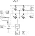
- FIG. 3 is a block schematic diagram of one form of the image correction system.
- the image sensor 30 provides an analogue output signal which is passed to a conditioning and digitising unit 31.
- Each successive frame of digitised information is stored in a separate one of a number of frame stores 32.
- Information is extracted from each frame store 32 in turn and passed to a transformation unit 33 which applies the appropriate corrections to the position of each pixel of information in that store.
- the transformed information is passed to a high resolution picture store 34 which holds a number of frames to make up a complete view.
- the contents of the picture store 34 are passed through a digital-to-analogue converter 35 to provide a video signal for display or other purposes.
- the transformation unit 33 may conveniently be a microprocessor which uses a number of algorithms to perform the pixel transformation.
- Information has to be supplied to a control unit 36 from pickoffs in the sensor drive and pickoff unit 37 indicating the elevation angle of the sensor, and from aircraft equipment 38 indicating the altitude, height and speed of the aircraft.
- the control unit applies the necessary control signals to the transformation unit 33, the sensor drive and pickoff unit 37 and other elements of the system.
- FIG. 4 Also shown in Figure 4 are the positions of some of the scan lines. Each will be separated from the next by an increment of elevation angle ⁇ , and hence the image lines IL on the ground will be separated by different distances as shown.
- the output lines OL on the display must be equally spaced, line selection therefore involves selecting only those image lines IL which coincide with, or are nearest to, output lines OL. This may be done, for example, by determining one at a time the position of each output line. This may be defined by the depth of the frame multiplied by the output line number divided by the total number of output lines in the frame. The position of each image line is compared with the current output line position, and when the position of an image line crosses the output line position then that image line is selected. The output line position is then incremented and the procedure repeated for each successive output line.
- L 2H sec ⁇ tan ⁇ /2
- H the height of the sensor above the ground
- ⁇ the angle of elevation to the centre of the field of view
- ⁇ the angular width of the field of view
- the scanning of the sensor and processing of the image data is a continuous process.
- the sensor is moved to the desired elevation angle by control means not shown in Figure 3. This involves moving the sensor rapidly between one position and the next, and controlling the direction of the frame scan information to the appropriate frame store.
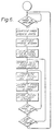
- Figure 6 is a flow chart illustrating the sequence of events followed in processing the information stored in each frame store 32.
- the image update rate is determined from data including the height above the ground and the speed of the aircraft carrying the sensor. If information is available then the appropriate frame store is accessed by the processor. After initialising the line and pixel positions, the next required scan line is determined as explained previously. Once this line is identified each required pixel on that line is identified and passed to the picture store. At the end of the scan line the next line is identified and the pixel selection processor is repeated. This continues until all required image information from that frame store has been used. The next frame store is then identified and the process if repeated.
- the information in the picture store may be displayed or may be passed to some other location for display or further processing.
- the basic sensor output may be transmitted, for example, to a ground station at which the processing may be performed.
- the scanner may be used for other purposes during its operation, if time is available during normal scanning. For example it may be possible to study a particular area of ground in more detail than is possible during normal operation.
- Standard image transformation techniques may be used, such as Walsh-Hadamard, to reduce the amount of storage required.
- group averaging or peak detection may be readily incorporated as examples of enhancing the final displayed image.
Landscapes
- Engineering & Computer Science (AREA)
- Multimedia (AREA)
- Signal Processing (AREA)
- Physics & Mathematics (AREA)
- General Physics & Mathematics (AREA)
- Health & Medical Sciences (AREA)
- Toxicology (AREA)
- Radar, Positioning & Navigation (AREA)
- Remote Sensing (AREA)
- Theoretical Computer Science (AREA)
- Image Processing (AREA)
Claims (7)
- Ein Bildkorrektursystem zur Schaffung einer Ansicht einer Szene (13), die durch einen elektro-optischen Rahmensensor (30) abgetastet wird,
gekennzeichnet durch
ein Steuermittel (36), das betätigbar ist, um zu bewirken, daß der Sensor (30) die Szene in einer Anzahl von separaten Rahmen (F1-F9) abtastet, von denen jeder unter einem unterschiedlichen Blickwinkel (α) gegenüber einem Satz von Datumachsen betrachtet wird, ein Meßwertgebermlttel (37), das dem Sensor (30) zugeordnet ist, um Signale zu erzeugen, die den Blickwinkel (α) eines jeden Rahmens (F1-F9) darstellen, ein Speichermittel (32), das betätigbar ist, um die Bildinformationen, die von jedem der Rahmen stammen, zu speichern, Schaltungsmittel (33), die betätigbar sind, um die in jedem Speichermittel (32) enthaltenen Bildinformationen umzuformen und so Verzerrungen, die durch die unterschiedlichen Blickwinkel verursacht werden, zu beseitigen, und einen Bildspeicher (34), der betätigbar ist, um die umgeformten Bildinformationen von jedem Rahmen (F1-F9) der Abtastung so zu speichern, daß die Inhalte des Bildspeichers (34) eine Ansicht der Szene aus einem bestimmten Blickwinkel darstellen. - Ein System wie in Anspruch 1 beansprucht,
gekennzeichnet durch
Sensorsteuermittel (37), die betätigbar sind, um die Stellung des Sensors unter der Steuerung des Steuermittels (36) zu steuern. - Ein System wie in Anspruch 2 beansprucht,
dadurch gekennzeichnet,
daß das Steuermittel (36) Signale von dem Meßwertgebermittel (37) erhält und diese dem Schaltungsmittel (33) zuführt. - Ein System wie in Anspruch 3 beansprucht,
dadurch gekennzeichnet,
daß der Sensor in einer Plattform montiert ist, die relativ zu der betrachteten Szene um ein Referenzachsensystem der Plattform bewegbar ist, wobei das Steuermittel (36) auch Signale erhält, die indikativ für die Höhe und Geschwindigkeit der Plattform relativ zu der betrachteten Szene (13) und die Signale von dem Meßwertgebermittel (37), die die Stellung des Sensors relativ zu der Plattform anzeigen, erhält. - Ein System wie in einem der Ansprüche 1 - 4 beansprucht,
dadurch gekennzeichnet,
daß das Speichermittel (32) einen separaten Speicher zum Speichern der Bildinformationen für jeden einer bestimmten Anzahl von Rahmen von (F1-F9) enthält. - Ein System wie in einem der vorhergehenden Ansprüche beansprucht,
dadurch gekennzeichnet,
daß das Schaltungsmittel (33) betätigbar ist, um für jeden Rahmen (F1-F9) jene Abtastlinien (IL), welche die Bildinformationen enthalten, die erforderlich sind, um dem Bildspeicher (34) zugeführt zu werden, auszuwählen und für jede solche Abtastlinie (IL) die Bildinformation auszuwählen, die dem Bildspeicher (34) zugeführt wird. - Ein Bildkorrektursystem zur Herstellung einer Ansicht einer Szene (13), die durch einen elektro-optischen Rahmensensor (30) abgetastet wird,
gekennzeichnet durch
ein Steuermittel (36), das betätigbar ist, um zu bewirken, daß der Sensor (30) die Szene (13) in einer Anzahl von separaten Rahmen (F1-F9) abtastet, von denen jeder unter einem unterschiedlichen Blickwinkel (α) relativ zu einem Satz von Datumachsen betrachtet wird, wobei jeder Rahmen Linien (IL) und Pixel (p) enthält, ein Meßwertgebermittel (37), das dem Sensor (30) zugeordnet ist, um Signale zu erzeugen, die den Blickwinkel (α) eines jeden Rahmens (F1-F9) darstellen, ein Speichermittel (32), das betätigbar ist, um die Bildinformationen, die von jedem der Rahmen stammen, zu speichern, ein Speichermittel (33), das betätigbar ist, um Linien (IL) und Pixel von jedem Rahmenspeichermittel (32) auszuwählen und so Verzerrungen, die durch die unterschiedlichen Blickwinkel (α) entstehen, zu beseitigen, und einen Bildspeicher (34), der betätigbar ist, um die umgeformten Bildinformationen von jedem Rahmen (F1-F9) der Abtastung so zu speichern, daß die Inhalte des Bildspeichers (34) eine Draufsicht der Szene von einer durch den Sensor (30) zur Verfügung gestellten perspektivischen Ansicht darstellen.
Applications Claiming Priority (2)
| Application Number | Priority Date | Filing Date | Title |
|---|---|---|---|
| GB08329459A GB2149258B (en) | 1983-11-04 | 1983-11-04 | Image correction system |
| GB8329459 | 1983-11-04 |
Publications (3)
| Publication Number | Publication Date |
|---|---|
| EP0145249A2 EP0145249A2 (de) | 1985-06-19 |
| EP0145249A3 EP0145249A3 (en) | 1988-11-17 |
| EP0145249B1 true EP0145249B1 (de) | 1994-04-06 |
Family
ID=10551218
Family Applications (1)
| Application Number | Title | Priority Date | Filing Date |
|---|---|---|---|
| EP84307602A Expired - Lifetime EP0145249B1 (de) | 1983-11-04 | 1984-11-02 | Bildverzerrungskorrektursystem für elektro-optische Bildsensoren |
Country Status (5)
| Country | Link |
|---|---|
| US (1) | US4630111A (de) |
| EP (1) | EP0145249B1 (de) |
| CA (1) | CA1223060A (de) |
| DE (1) | DE3486295T2 (de) |
| GB (1) | GB2149258B (de) |
Families Citing this family (26)
| Publication number | Priority date | Publication date | Assignee | Title |
|---|---|---|---|---|
| GB2180714B (en) * | 1985-08-22 | 1989-08-16 | Rank Xerox Ltd | Image apparatus |
| GB2188205B (en) * | 1986-03-20 | 1990-01-04 | Rank Xerox Ltd | Imaging apparatus |
| GB2189365A (en) * | 1986-03-20 | 1987-10-21 | Rank Xerox Ltd | Imaging apparatus |
| DE3614159A1 (de) * | 1986-04-26 | 1988-02-04 | Messerschmitt Boelkow Blohm | Verfahren und vorrichtung zur bildaufnahme eines objektes in zeilen |
| US4688091A (en) * | 1986-05-06 | 1987-08-18 | Ford Aerospace & Communications Corporation | Spacecraft camera image registration |
| US4688092A (en) * | 1986-05-06 | 1987-08-18 | Ford Aerospace & Communications Corporation | Satellite camera image navigation |
| NL8701148A (nl) * | 1987-05-13 | 1988-12-01 | Eurosense Belfotop S A | Inrichting voor de kleurcorrectie c.q. -calibratie van het kleurenbeeld op een monitor. |
| DE3830577C3 (de) * | 1988-09-08 | 1995-02-23 | Deutsche Aerospace | Digitale Abtastung |
| DE3829300A1 (de) * | 1987-09-22 | 1989-03-30 | Messerschmitt Boelkow Blohm | Verfahren und vorrichtung zur abtastung eines objektes |
| US5043924A (en) * | 1987-09-22 | 1991-08-27 | Messerschmitt-Bolkow-Blohm Gmbh | Method and apparatus for scanning an object |
| JP3138264B2 (ja) * | 1988-06-21 | 2001-02-26 | ソニー株式会社 | 画像処理方法及び装置 |
| US5140436A (en) * | 1989-11-02 | 1992-08-18 | Eastman Kodak Company | Pre-event/post-event recording in a solid state fast frame recorder |
| US5196938A (en) * | 1989-11-20 | 1993-03-23 | Eastman Kodak Company | Solid state fast frame recorder having independently selectable frame rate and exposure |
| US5140434A (en) * | 1990-01-29 | 1992-08-18 | Eastman Kodak Company | Record on command recording in a solid state fast frame recorder |
| GB9018709D0 (en) * | 1990-08-25 | 1990-10-10 | Hunting Eng Ltd | Surveillance devices |
| GB2256989B (en) * | 1991-06-21 | 1995-02-08 | Sony Broadcast & Communication | Video image capture apparatus |
| US5481479A (en) * | 1992-12-10 | 1996-01-02 | Loral Fairchild Corp. | Nonlinear scanning to optimize sector scan electro-optic reconnaissance system performance |
| US5278402A (en) * | 1993-06-09 | 1994-01-11 | Litton Systems | Real-scene dispersion sensor detecting two wavelengths and determining time delay |
| FR2707129B1 (fr) * | 1993-06-28 | 1995-10-20 | Salaberry De Bernard Luicen Ch | Dispositif de prise de vue à grand champ et à haute résolution pour véhicule aérien. |
| FR2752619B1 (fr) | 1996-08-23 | 1998-11-13 | Thomson Csf | Procede et dispositif de reconnaissance air-sol pour equipement optronique |
| US6133943A (en) * | 1996-09-30 | 2000-10-17 | Intel Corporation | Method and apparatus for producing a composite image |
| DE19645981C2 (de) * | 1996-11-07 | 1999-07-01 | Ingbuero Fuer Elektro Mechanis | Vorrichtung zum Erzeugen kartennormierter Bilder |
| AU2154000A (en) | 1998-12-07 | 2000-06-26 | Universal City Studios, Inc. | Image correction method to compensate for point of view image distortion |
| US7949241B2 (en) * | 2009-09-29 | 2011-05-24 | Raytheon Company | Anamorphic focal array |
| CN108286961A (zh) * | 2018-01-26 | 2018-07-17 | 广州市红鹏直升机遥感科技有限公司 | 一种拼接式航空倾斜摄影系统 |
| CN112212832B (zh) * | 2019-07-10 | 2023-04-14 | 瞰景科技发展(上海)有限公司 | 一种提升倾斜摄影航测效率装置和方法 |
Family Cites Families (12)
| Publication number | Priority date | Publication date | Assignee | Title |
|---|---|---|---|---|
| US3632870A (en) * | 1966-01-03 | 1972-01-04 | Texas Instruments Inc | Scanner system |
| US3564133A (en) * | 1967-01-16 | 1971-02-16 | Itek Corp | Transformation and registration of photographic images |
| US3915569A (en) * | 1972-08-08 | 1975-10-28 | Franz Wolfgang Polzleitner | Ortho projector to make photo maps from aerial photographs |
| FR2244319B1 (de) * | 1973-09-17 | 1979-01-05 | Ver Flugtechnische Werke | |
| GB1472346A (en) * | 1974-07-06 | 1977-05-04 | Grundig Emv | Aerial reconnaissance apparatus |
| NL7613491A (nl) * | 1976-12-03 | 1978-06-06 | Optische Ind De Oude Delft Nv | Stelsel voor het zwaaisgewijs aftasten van een, een bepaalde soort van een straling emitterend gebied, en het verwerken van de hierbij opge- vangen straling tot een voor weergave of regis- tratie geschikte vorm. |
| US4496972A (en) * | 1980-05-10 | 1985-01-29 | Deutsche Forschungs-Und Versuchsanstalt Fur Luft-Und Raumfahrt E.V. | Method for the representation of video images or scenes, in particular aerial images transmitted at reduced frame rate |
| GB2097625B (en) * | 1981-04-23 | 1985-06-19 | Ferranti Ltd | Airborne observation device |
| NL8103452A (nl) * | 1981-07-21 | 1983-02-16 | Rsv Gusto Eng Bv | Hefinrichting voor een kunstmatig eiland of werkplatform. |
| US4463380A (en) * | 1981-09-25 | 1984-07-31 | Vought Corporation | Image processing system |
| SE427516B (sv) * | 1981-11-10 | 1983-04-11 | Ericsson Telefon Ab L M | Sett och anordning for att korrigera distortion i en pa elektronisk veg upptecknad av bildelement lengs linjer uppbyggd bild |
| US4485409A (en) * | 1982-03-29 | 1984-11-27 | Measuronics Corporation | Data acquisition system for large format video display |
-
1983
- 1983-11-04 GB GB08329459A patent/GB2149258B/en not_active Expired
-
1984
- 1984-10-30 US US06/666,374 patent/US4630111A/en not_active Expired - Fee Related
- 1984-11-02 EP EP84307602A patent/EP0145249B1/de not_active Expired - Lifetime
- 1984-11-02 DE DE3486295T patent/DE3486295T2/de not_active Expired - Fee Related
- 1984-11-02 CA CA000466924A patent/CA1223060A/en not_active Expired
Non-Patent Citations (2)
| Title |
|---|
| K. Ulbricht: "DFLR's DIBIAS, same publication, pp 6-1 to 6-12. * |
| T.R. Berry, "Image Generation and Display", AGARD lecture series, no. 119, June 1982, pp 4-1 to 4-25. * |
Also Published As
| Publication number | Publication date |
|---|---|
| EP0145249A3 (en) | 1988-11-17 |
| DE3486295T2 (de) | 1994-07-28 |
| DE3486295D1 (de) | 1994-05-11 |
| GB2149258A (en) | 1985-06-05 |
| CA1223060A (en) | 1987-06-16 |
| GB2149258B (en) | 1987-03-11 |
| EP0145249A2 (de) | 1985-06-19 |
| US4630111A (en) | 1986-12-16 |
Similar Documents
| Publication | Publication Date | Title |
|---|---|---|
| US4630111A (en) | Image distortion correction system for electro-optic sensors | |
| JP3392422B2 (ja) | 2軸画像運動補償を行う電子光学的画像検知アレイ | |
| US4484192A (en) | Moving map display | |
| US5586231A (en) | Method and device for processing an image in order to construct from a source image a target image with charge of perspective | |
| US5596494A (en) | Method and apparatus for acquiring digital maps | |
| US8581981B2 (en) | Optical imaging system for unmanned aerial vehicle | |
| US9485499B2 (en) | System and method for processing multicamera array images | |
| US5689302A (en) | Higher definition video signals from lower definition sources | |
| US5428390A (en) | Apparatus and method for focal plane zoom and pan | |
| EP0139384B1 (de) | Anzeigeeinrichtungen | |
| EP0737845B1 (de) | Auf einem luftfahrzeug angebrachter integrierter fotoapparat | |
| JP2000504507A (ja) | 像動き補償機能を有した電気光学式ステップフレームカメラシステム | |
| US4418360A (en) | Image processing | |
| EP0503103B1 (de) | Elektronischer Zoom für Zeilenabtaster mit breitem Sichtwinkel | |
| US6320611B1 (en) | Method and device for air-ground recognition for optoelectronic equipment | |
| US3952151A (en) | Method and apparatus for stabilized reproduction of remotely-sensed images | |
| US5523887A (en) | Stabilized imaging system | |
| GB2328098A (en) | Image scanning system for panning across a viewed scene | |
| EP0766113A2 (de) | Asphärische Elemente für Infrarot-Abbildungssystem | |
| EP0673575B1 (de) | Videosignale höherer auflösung erzeugt aus quellen niedrigerer auflösung | |
| TW201502572A (zh) | 掃描器的偵測器陣列、線掃描器以及掃描表面的方法 | |
| WO2005048605A1 (en) | Synthetic electronic imaging system | |
| GB2127649A (en) | Compensation for video sensor movement | |
| JP2617261B2 (ja) | 画素情報処理方法 | |
| Lareau | Optimum coverage EO framing camera |
Legal Events
| Date | Code | Title | Description |
|---|---|---|---|
| PUAI | Public reference made under article 153(3) epc to a published international application that has entered the european phase |
Free format text: ORIGINAL CODE: 0009012 |
|
| AK | Designated contracting states |
Designated state(s): DE FR IT SE |
|
| PUAL | Search report despatched |
Free format text: ORIGINAL CODE: 0009013 |
|
| AK | Designated contracting states |
Kind code of ref document: A3 Designated state(s): DE FR IT SE |
|
| 17P | Request for examination filed |
Effective date: 19881130 |
|
| RAP1 | Party data changed (applicant data changed or rights of an application transferred) |
Owner name: GEC-FERRANTI DEFENCE SYSTEMS LTD. |
|
| 17Q | First examination report despatched |
Effective date: 19900907 |
|
| GRAA | (expected) grant |
Free format text: ORIGINAL CODE: 0009210 |
|
| RAP1 | Party data changed (applicant data changed or rights of an application transferred) |
Owner name: GEC-MARCONI AVIONICS (HOLDINGS) LIMITED |
|
| AK | Designated contracting states |
Kind code of ref document: B1 Designated state(s): DE FR IT SE |
|
| ITF | It: translation for a ep patent filed | ||
| REF | Corresponds to: |
Ref document number: 3486295 Country of ref document: DE Date of ref document: 19940511 |
|
| ET | Fr: translation filed | ||
| PGFP | Annual fee paid to national office [announced via postgrant information from national office to epo] |
Ref country code: FR Payment date: 19940930 Year of fee payment: 11 |
|
| PGFP | Annual fee paid to national office [announced via postgrant information from national office to epo] |
Ref country code: SE Payment date: 19941003 Year of fee payment: 11 |
|
| PGFP | Annual fee paid to national office [announced via postgrant information from national office to epo] |
Ref country code: DE Payment date: 19941227 Year of fee payment: 11 |
|
| EAL | Se: european patent in force in sweden |
Ref document number: 84307602.7 |
|
| PLBE | No opposition filed within time limit |
Free format text: ORIGINAL CODE: 0009261 |
|
| STAA | Information on the status of an ep patent application or granted ep patent |
Free format text: STATUS: NO OPPOSITION FILED WITHIN TIME LIMIT |
|
| 26N | No opposition filed | ||
| PG25 | Lapsed in a contracting state [announced via postgrant information from national office to epo] |
Ref country code: SE Effective date: 19951103 |
|
| PG25 | Lapsed in a contracting state [announced via postgrant information from national office to epo] |
Ref country code: FR Effective date: 19960731 |
|
| PG25 | Lapsed in a contracting state [announced via postgrant information from national office to epo] |
Ref country code: DE Effective date: 19960801 |
|
| EUG | Se: european patent has lapsed |
Ref document number: 84307602.7 |
|
| REG | Reference to a national code |
Ref country code: FR Ref legal event code: ST |
|
| APAH | Appeal reference modified |
Free format text: ORIGINAL CODE: EPIDOSCREFNO |