EP0144641A2 - Service derrick for a well pump - Google Patents
Service derrick for a well pump Download PDFInfo
- Publication number
- EP0144641A2 EP0144641A2 EP84112444A EP84112444A EP0144641A2 EP 0144641 A2 EP0144641 A2 EP 0144641A2 EP 84112444 A EP84112444 A EP 84112444A EP 84112444 A EP84112444 A EP 84112444A EP 0144641 A2 EP0144641 A2 EP 0144641A2
- Authority
- EP
- European Patent Office
- Prior art keywords
- mast
- stand
- assembly rig
- rig according
- lifting device
- Prior art date
- Legal status (The legal status is an assumption and is not a legal conclusion. Google has not performed a legal analysis and makes no representation as to the accuracy of the status listed.)
- Granted
Links
- 238000004873 anchoring Methods 0.000 claims description 2
- 230000008878 coupling Effects 0.000 description 4
- 238000010168 coupling process Methods 0.000 description 4
- 238000005859 coupling reaction Methods 0.000 description 4
- 238000009434 installation Methods 0.000 description 4
- 238000012423 maintenance Methods 0.000 description 3
- 238000005452 bending Methods 0.000 description 2
- 239000003673 groundwater Substances 0.000 description 2
- 210000003205 muscle Anatomy 0.000 description 2
- XLYOFNOQVPJJNP-UHFFFAOYSA-N water Substances O XLYOFNOQVPJJNP-UHFFFAOYSA-N 0.000 description 2
- 230000005540 biological transmission Effects 0.000 description 1
- 230000003387 muscular Effects 0.000 description 1
- 230000008520 organization Effects 0.000 description 1
- 230000001681 protective effect Effects 0.000 description 1
- 230000000630 rising effect Effects 0.000 description 1
- 239000008400 supply water Substances 0.000 description 1
Images
Classifications
-
- E—FIXED CONSTRUCTIONS
- E21—EARTH DRILLING; MINING
- E21B—EARTH DRILLING, e.g. DEEP DRILLING; OBTAINING OIL, GAS, WATER, SOLUBLE OR MELTABLE MATERIALS OR A SLURRY OF MINERALS FROM WELLS
- E21B15/00—Supports for the drilling machine, e.g. derricks or masts
-
- E—FIXED CONSTRUCTIONS
- E03—WATER SUPPLY; SEWERAGE
- E03B—INSTALLATIONS OR METHODS FOR OBTAINING, COLLECTING, OR DISTRIBUTING WATER
- E03B3/00—Methods or installations for obtaining or collecting drinking water or tap water
- E03B3/06—Methods or installations for obtaining or collecting drinking water or tap water from underground
- E03B3/08—Obtaining and confining water by means of wells
- E03B3/15—Keeping wells in good condition, e.g. by cleaning, repairing, regenerating; Maintaining or enlarging the capacity of wells or water-bearing layers
-
- E—FIXED CONSTRUCTIONS
- E21—EARTH DRILLING; MINING
- E21B—EARTH DRILLING, e.g. DEEP DRILLING; OBTAINING OIL, GAS, WATER, SOLUBLE OR MELTABLE MATERIALS OR A SLURRY OF MINERALS FROM WELLS
- E21B19/00—Handling rods, casings, tubes or the like outside the borehole, e.g. in the derrick; Apparatus for feeding the rods or cables
- E21B19/02—Rod or cable suspensions
Definitions
- the invention relates to an assembly rig for a well pump, which has a riser pipe string made up of several detachably coupled riser pipes, a hollow stand and a drive device detachably attached to the stand.
- Well pumps are mainly used to supply water to the rural population in developing countries in the arid regions of the world. They are generally operated using muscle power and extract groundwater from depths of up to 100 m. Most of the locations of the well pumps are far away and can only be reached by off-road vehicles.
- Runnenpumpen for installation, maintenance and repair work on such B it's been necessary to bring heavy lifting to the installation site. This presupposes that appropriately equipped assembly teams, an organization of the necessary operational trips and corresponding financial means are available. Often this is not the case, and therefore in many cases there is no maintenance or repair work on the well pumps.
- the invention is therefore based on the object of developing a simple, lightweight and inexpensive device which is preferably delivered together with each well pump or group of such pumps and remains at or near the installation site, preferably in the care of a person responsible for pump operation, who without special training should be able to set up the device on the well pump when necessary and thereby at least prepare the necessary maintenance or repair work.
- An assembly rig according to the invention for a certain load-bearing capacity can be made considerably lighter and simpler and, accordingly, easier to transport and easier to set up than hitherto used for comparable purposes with the same lifting height and load-bearing capacity. If the terrain is not too difficult, a man of average strength can carry the entire assembly rig according to the invention on foot for longer distances or transport it by bicycle, so that a single assembly rig can be used in suitable cases for several well pumps that are not too far apart.
- the required stability of the assembly rig at the installation site results from the fact that the mast on the stand of Pump is supported.
- the stand is designed to be sufficiently strong in any case because of the loads occurring during the operation of the pump in order to withstand the loads that can occur when the assembly rig according to the invention is installed and used.
- the lifting device can be, for example, a cable winch or chain winch or a hoist that is commercially available and works with intermittent cable clamping.
- An additional rope can be provided as a lifting device for not too deep well pumps with a correspondingly light riser pipe run, which runs over at least one additional deflection device that can be anchored to the stand and is pulled with muscular strength.
- At least one upper part of the mast is preferably permanently connected to the deflection device, tension member and lifting device. This prevents the individual parts of the assembly rig from being misused and lost.
- the non-detachable connection can be made simply by the tensile member passing through the lifting and deflecting device having non-detachable fittings at both ends.
- the lifting device has a hitch which can be anchored on the stand such that the tension member runs into the lifting device at a position diametrically opposite the stand axis with respect to the mast axis.
- the mast is largely kept free of bending moments when using the assembly rig according to the invention; it is essentially only subjected to pressure and can accordingly be slim and light.
- the lifting device is designed as a hoist, it preferably additionally has a guide with which is guided vertically on the mast. As a result, the lifting device anchored to the stand is additionally stabilized so that it cannot oscillate, which would make its handling more difficult and would disrupt the symmetry of the tension member with respect to the mast axis.
- the lifting device is designed as a cable or chain winch
- the hitching device can expediently be rigidly coupled to the stand.
- the mast is preferably held in a head part and a foot part, which are fastened or can be fastened to the head or foot end of the stand.
- the head part is, for example, a plate which has a hole for inserting the mast and a further fastening point for anchoring the lifting device.
- the deflection device preferably includes a deflection roller, the radius of which corresponds at least approximately to the distance between the mast and column axis, which is determined by the head and foot part.
- the transport of the assembly rig according to the invention can be facilitated in that the mast is divided into an upper part, to which the deflection device is attached, and a lower part in the form of a riser pipe. If a well pump is installed, there is usually at least one standpipe left, which can then be used as part of the mast.
- the tension member has a tap at one end assigned to the stand, to which either the drive device or a Yoke for lifting the tubing string is attached.
- the well pump has a foundation 10 made of concrete, from which a casing tube 12 extends vertically downwards into a groundwater-bearing layer of earth.
- the jacket tube 12 encloses, at a radial distance, a riser pipe line from riser pipes 14 which are connected to one another by pipe couplings 16 and are centered in the jacket pipe 12 by star-shaped support rings 18.
- a stand 20 On the foundation 10 is a stand 20 with a laterally projecting, plate-shaped head part 22 and a plate-shaped foot part 24, which is screwed onto the foundation 10.
- An intermediate housing 26 is fastened on the head part 22 and has a water outlet 28 and carries a drive device 30.
- the drive device 30 is a transmission which can be driven with a hand crank 32 and in turn drives a shaft train (not shown) which extends downward through the riser pipe train and is coupled to a helical rotor.
- the rotor works in a helical stator, which is arranged in the lower end region of the casing tube 12 and can be pulled out through the casing tube together with the riser tubes 14.
- the well pump can also be designed as a piston pump, for example; in this case, the drive device is designed such that it converts the rotation of a hand crank or swivels of a pump arm into rising and falling piston movements.
- Such pumps are known for example from the magazine "World Water” from February 1983.
- the pump is assigned an assembly rig with a slim, tubular mast 34, which is composed of an upper part 36 and a lower part 38.
- the lower part 38 is identical in all details to a surplus riser pipe 14 including the associated pipe coupling 16.
- the total height of the mast 34 is greater by at least the height of the stand 20 than the length of each individual riser pipe 14 including the pipe coupling 16.
- a deflection device 40 is arranged, which has a deflection roller 42.
- the axis of rotation of the deflection roller 42 intersects the mast axis 44 and extends in the illustrated, assembled state of the assembly rig at a right angle to the vertical plane in which the column axis 46 and the mast axis 44 parallel to it lie.
- the deflection roller 42 has a deflection radius which corresponds to the distance between the two axes 44 and 46.
- the upper half of the deflection roller 42 is covered with a protective hood 48.
- a tension member 50 which is formed in the example shown by a rope, but could also be formed by a chain.
- an annular fitting 52 is fastened, on which a yoke 56 is suspended via a tap 54.
- the yoke 56 has a central recess 58 which is open at the side and is dimensioned such that the risers 14 can be grasped one after the other below their pipe coupling 16 with the yoke 56 in order to be pulled out of the jacket pipe 12 or lowered into it.
- the drive device 30 can be attached to the tap pot 54 for its removal or attachment, for example on two shaft ends.
- the other strand of the tension member 50 runs through a lifting device 60, which is shown as a commercial hoist with alternating jaw pairs 62, an actuating lever 64 and a brake lever 66.
- the lifting device 60 has a hitch 68 in the form of a hook and a tubular guide 70 with which it is guided on the lower part 38 of the mast 34 so as to be displaceable in its longitudinal direction.
- the tension member 50 is led out downward or laterally out of the lifting device 60 and has a further fitting 72 at its end.
- the lower part 38 of the mast 34 is inserted from above through a circular hole 74 in the head part 22 of the stand 20 and engages in a sleeve-shaped holder 76 which is formed on the foot part 24. As a result, the entire mast 34 is rigidly connected to the stand 20, so that it requires no further support.
- the head part 22 has a further fastening point 78 in the form of a hole which lies on the same radius starting from the stator axis 46 as the center of the hole 74, which determines the position of the stator axis 46.
- the center distance of the fastening point 78 from the stator axis 46 is twice as large as the center distance of the hole 74 from the stator axis.
- a chain 80 extends through the hole 78 and is hooked into the hitch 68 and fixed to the head part 22 of the stand 20 with a bolt 82.
- the hitching device 68 can have a stiff bracket which is fastened to the lifting device and can be attached laterally to the head part 22 such that the lifting device is rigid with the stand 20 via the hitching device and the head part 22 can be coupled.
- an additional rope 84 can be attached to the tension member 50, which runs over at least one additional deflection roller 86 anchored to the stand 20, possibly forms a pulley block with several such deflection rollers and also forms a lifting device which can be actuated with muscle power .
Abstract
Eine Brunnenpumpe hat einen Steigrohrstrang aus mehreren lösbar miteinander gekuppelten Steigrohren (14), einen hohen Ständer (20) und eine lösbar auf dem Ständer (20) befestigte Antriebsvorrichtung (30). Das zugehörige Montagerigg besteht aus einem Mast (34), der am Ständer (20) abstützbar ist, einer Umlenkvorrichtung (40), die am oberen Ende des Mastes (34) angeordnet ist, und einem Zugglied (50), das über die Umlenkvorrichtung (40) geführt, an einem seiner Enden zum Abhängen eines Steigrohrs (14) und am anderen Ende zum Anhängen an eine Hebevorrichtung (60) ausgebildet ist. Das Montagerigg ist erheblich leichter und einfacher und läßt sich dementsprechend einfacher befördern und ausfstellen als bisher übliches Hubgerät von gleicher Hubhöhe und Tragkraft.A well pump has a riser pipe line consisting of several riser pipes (14) detachably coupled to one another, a tall stand (20) and a drive device (30) detachably attached to the stand (20). The associated assembly rig consists of a mast (34) which can be supported on the stand (20), a deflection device (40) which is arranged at the upper end of the mast (34), and a tension member (50) which is connected to the deflection device ( 40), is formed at one end for hanging a riser pipe (14) and at the other end for hanging on a lifting device (60). The assembly rig is considerably lighter and simpler and can accordingly be transported and deployed more easily than previously conventional lifting equipment with the same lifting height and load capacity.
Description
Die Erfindung betrifft ein Montagerigg für eine Brunnenpumpe, die einen Steigrohrstrang aus mehreren lösbar miteinander gekuppelten Steigrohren, einen hohlen Ständer und eine lösbar auf dem Ständer befestigte Antriebsvorrichtung aufweist.The invention relates to an assembly rig for a well pump, which has a riser pipe string made up of several detachably coupled riser pipes, a hollow stand and a drive device detachably attached to the stand.
Brunnenpumpen werden-überwiegend zur Wasserversorgung der Landbevölkerung in Entwicklungsländern in den Trockengebieten der Erde eingesetzt. Sie werden im allgemeinen durch Muskelkraft betrieben und fördern Grundwässer aus Tiefen bis zu 100 m. Meist sind die Aufstellungsorte der Brunnenpumpen weit abgelegen und nur mit geländegängigen Kraftwagen zu erreichen.Well pumps are mainly used to supply water to the rural population in developing countries in the arid regions of the world. They are generally operated using muscle power and extract groundwater from depths of up to 100 m. Most of the locations of the well pumps are far away and can only be reached by off-road vehicles.
Für Montage-, Wartungs- und Reparaturarbeiten an solchen Brunnenpumpen ist es bisher erforderlich, schweres Hubgerät an den Einbauort zu bringen. Dies setzt voraus, daß entsprechend ausgerüstete Montagetrupps, eine Organisation der nötigen Einsatzfahrten und entsprechende finanzielle Mittel vorhanden sind. Häufig ist dies nicht der Fall, und deshalb unterbleiben in vielen Fällen notwendige Wartungs- oder Reparaturarbeiten an den Brunnenpumpen.Runnenpumpen for installation, maintenance and repair work on such B it's been necessary to bring heavy lifting to the installation site. This presupposes that appropriately equipped assembly teams, an organization of the necessary operational trips and corresponding financial means are available. Often this is not the case, and therefore in many cases there is no maintenance or repair work on the well pumps.
Der Erfindung liegt deshalb die Aufgabe zugrunde, eine einfache, leichte und billige Vorrichtung zu entwickeln, die vorzugsweise zusammen mit jeder Brunnenpumpe oder Gruppe solcher Pumpen geliefert wird und an oder nahe deren Aufstellungsort bleibt, vorzugsweise in der Obhut eine für den Pumpenbetrieb verantwortlichen Person, die ohne besondere Ausbildung imstande sein soll, die Vorrichtung bei Bedarf an der Brunnenpumpe aufzustellen und dadurch die erforderlichen Wartungs- oder Reparaturarbeiten mindestens vorzubereiten.The invention is therefore based on the object of developing a simple, lightweight and inexpensive device which is preferably delivered together with each well pump or group of such pumps and remains at or near the installation site, preferably in the care of a person responsible for pump operation, who without special training should be able to set up the device on the well pump when necessary and thereby at least prepare the necessary maintenance or repair work.
Die Aufgabe ist erfindungsgemäß durch ein Montagerigg gelöst, das gekennzeichnet ist durch
- - einen Mast, der am Ständer abstützbar ist,
- - eine Umlenkvorrichtung, die am oberen Ende des Mastes angeordnet ist,
- - und ein Zugglied, das-über die Umlenkvorrichtung geführt-, an einem seiner Enden zum Anhängen eines Steigrohrs und am anderen Ende zum Anhängen an eine Hebevorrichtung ausgebildet ist.
- - a mast that can be supported on the stand,
- a deflection device which is arranged at the upper end of the mast,
- - And a tension member, which is guided over the deflection device, is formed at one end for attaching a riser pipe and at the other end for attaching to a lifting device.
Ein erfindungsgemäßes Montagerigg für eine bestimmte Tragkraft läßt sich erheblich leichter und einfacher gestalten und dementsprechend leichter befördern und einfacher aufstellen als bisher für vergleichbare Zwecke-übliches Hubgerät von gleicher Hubhöhe und Tragkraft. Bei nicht allzu schwierigen Geländeverhältnissen kann ein durchschnittlich kräftiger Mann das gesamte erfindungsgemäße Montagerigg-über längere Strecken zu Fuß tragen oder mit dem Fahrrad transportieren, so daß ein einziges Montagerigg in geeigneten Fällen für mehrere, nicht allzu weit voneinander entfernte Brunnenpumpen verwendet werden kann.An assembly rig according to the invention for a certain load-bearing capacity can be made considerably lighter and simpler and, accordingly, easier to transport and easier to set up than hitherto used for comparable purposes with the same lifting height and load-bearing capacity. If the terrain is not too difficult, a man of average strength can carry the entire assembly rig according to the invention on foot for longer distances or transport it by bicycle, so that a single assembly rig can be used in suitable cases for several well pumps that are not too far apart.
Die erforderliche Stabilität des Montageriggs am Aufstellungsort ergibt sich dadurch, daß der Mast am Ständer der Pumpe abgestützt wird. Der Ständer ist wegen der im Betrieb der Pumpe auftretenden Belastungen in jedem Fall hinreichend kräftig gestaltet, um auch den Belastungen standzuhalten, die bei Aufstellung und Benutzung des erfindungsgemäßen Montageriggs auftreten können.The required stability of the assembly rig at the installation site results from the fact that the mast on the stand of Pump is supported. The stand is designed to be sufficiently strong in any case because of the loads occurring during the operation of the pump in order to withstand the loads that can occur when the assembly rig according to the invention is installed and used.
Die Hebevorrichtung kann beispielsweise eine Seil- oder Kettenwinde oder ein mit intermittierender Seilklemmung arbeitender Hubzug handelsüblicher Bauweise sein. Als Hebevorrichtung für nicht allzu tiefe Brunnenpumpen mit entsprechend leichtem Steigrohrstrang kann ein zusätzliches Seil vorgesehen sein, das-über mindesten eine zusätzliche, am Ständer verankerbare Umlenkvorrichtung läuft und mit Muskelkraft gezogen wird.The lifting device can be, for example, a cable winch or chain winch or a hoist that is commercially available and works with intermittent cable clamping. An additional rope can be provided as a lifting device for not too deep well pumps with a correspondingly light riser pipe run, which runs over at least one additional deflection device that can be anchored to the stand and is pulled with muscular strength.
Vorzugsweise ist mindestens ein Oberteil des Mastes mit Umlenkvorrichtung, Zugglied und Hebevorrichtung unlösbar verbunden.'Dadurch wird verhindert, daß die einzelnen Teile des Montageriggs zweckentfremdet werden und verlorengehen können. Die unlösbare Verbindung kann einfach dadurch hergestellt sein, chß das durch Hebe- und Umlenkvorrichtung hindurchgeführte Zugglied an seinen beiden Enden unlösbare Beschläge aufweist.At least one upper part of the mast is preferably permanently connected to the deflection device, tension member and lifting device. This prevents the individual parts of the assembly rig from being misused and lost. The non-detachable connection can be made simply by the tensile member passing through the lifting and deflecting device having non-detachable fittings at both ends.
Es ist ferner zweckmäßig, wenn die Hebevorrichtung eine Anhängevorrichtung aufweist, die am Ständer derart verankerbar ist, daß das Zugglied an einer der Ständerachse in bezug auf die Mastachse diametral gegenüberliegenden Stelle in die Hebevorrichtung einläuft. Dadurch wird der Mast bei Benutzung des erfindungsgemäßen Montageriggs von Biegemomenten weitgehend freigehalten; er wird im wesentlichen nur auf Druck belastet und kann dementsprechend schlank und leicht gestaltet sein.It is also expedient if the lifting device has a hitch which can be anchored on the stand such that the tension member runs into the lifting device at a position diametrically opposite the stand axis with respect to the mast axis. As a result, the mast is largely kept free of bending moments when using the assembly rig according to the invention; it is essentially only subjected to pressure and can accordingly be slim and light.
Wenn die Hebevorrichtung als Hubzug ausgebildet ist, weist sie vorzugsweise zusätzlich eine Führung auf, mit der sie am Mast senkrecht verschiebbar geführt ist. Dadurch wird die am Ständer verankerte Hebevorrichtung zusätzlich stabilisiert, so daß sie nicht pendeln kann, was ihre Handhabung erschweren und die Symmetrie des Zuggliedes in bezug auf die Mastachse stören würde.If the lifting device is designed as a hoist, it preferably additionally has a guide with which is guided vertically on the mast. As a result, the lifting device anchored to the stand is additionally stabilized so that it cannot oscillate, which would make its handling more difficult and would disrupt the symmetry of the tension member with respect to the mast axis.
Wenn die Hebevorrichtung dagegen als Seil- oder Kettenwinde ausgebildet ist, dann ist die Anhängevorrichtung zweckmäßigerweise mit dem Ständer starr kuppelbar.If, on the other hand, the lifting device is designed as a cable or chain winch, then the hitching device can expediently be rigidly coupled to the stand.
Der Mast ist vorzugsweise in einem Kopfteil und einem Fußteil gehalten, die am Kopf- bzw. Fußende des Ständers befestigt oder befestigbar sind.The mast is preferably held in a head part and a foot part, which are fastened or can be fastened to the head or foot end of the stand.
Das Kopfteil ist beispielsweise eine Platte, die zum Einstecken des Mastes ein Loch und zum Verankern der Hebevorrichtung eine weitere Befestigungsstelle aufweist.The head part is, for example, a plate which has a hole for inserting the mast and a further fastening point for anchoring the lifting device.
Zur Umlenkvorrichtung gehört vorzugsweise eine Umlenkrolle, deren Radius zumindest annähernd mit dem durch Kopf-und Fußteil bestimmten Abstand zwischen Mast- und Ständerachse-übereinstimmt. Dadurch läßt sich der Mast in jeder beliebigen Stellung des Zuggliedes von Biegebelastungen fast vollständig freihalten.The deflection device preferably includes a deflection roller, the radius of which corresponds at least approximately to the distance between the mast and column axis, which is determined by the head and foot part. As a result, the mast can be kept almost completely free of bending loads in any position of the tension member.
Der Transport des erfindungsgemäßen Montageriggs kann dadurch erleichtert sein, daß der Mast in ein Oberteil, an dem die Umlenkvorrichtung befestigt ist, und ein Unterteil in Gestalt eines Steigrohrs unterteilt ist. Wenn eine Brunnenpumpe eingebaut wird, bleibt meist mindestens ein Steigrohr-übrig, das dann als Bestandteil des Mastes verwendet werden kann.The transport of the assembly rig according to the invention can be facilitated in that the mast is divided into an upper part, to which the deflection device is attached, and a lower part in the form of a riser pipe. If a well pump is installed, there is usually at least one standpipe left, which can then be used as part of the mast.
Schließlich ist es vorteilhaft, wenn das Zugglied an einem dem Ständer zugeordneten Ende eine Hahnepot aufweist, an die wahlweise die Antriebsvorrichtung oder ein Joch zum Heben des Steigrohrstrangs anhängbar ist.Finally, it is advantageous if the tension member has a tap at one end assigned to the stand, to which either the drive device or a Yoke for lifting the tubing string is attached.
Ein Ausführungsbeispiel der Erfindung wird im folgenden anhand einer schematischen Zeichnung mit weiteren Einzelheiten erläutert. Es zeigt:
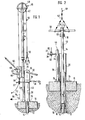
- Fig.l eine teilweise als senkrechter Schnitt dargestellte Seitenansicht der in Bodennähe und-über dem Boden angeordneten Teile einer Brunnenpumpe mit einem erfindungsgemäßen Montagerigg und
- Fig.2 Einzelheiten aus Fig.l in einem vergrößerten senkrechten Schnitt.
- Fig.l is a side view, shown partly as a vertical section, of the parts of a well pump arranged near the floor and above the floor with a mounting rig according to the invention and
- 2 details from Fig.l in an enlarged vertical section.
Die Brunnenpumpe hat ein Fundament 10 aus Beton, von dem sich ein Mantelrohr 12 senkrecht nach unten bis in eine grundwasserführende Erdschicht erstreckt. Das Mantelrohr 12 umschließt mit radialem Abstand einen Steigrohrstrang aus Steigrohren 14, die durch Rohrkupplungen 16 miteinander verbunden und durch sternförmige Stützringe 18 im Mantelrohr 12 zentriert sind.The well pump has a
Auf dem Fundament 10 steht ein Ständer 20 mit einem seitlich auskragenden, plattenförmigen Kopfteil 22 und einem ebenfalls plattenförmigen Fußteil 24, das auf dem Fundament 10 festgeschraubt ist. Auf dem Kopfteil 22 ist ein Zwischengehäuse 26 befestigt, das einen Wasserauslauf 28. aufweist und eine Antriebsvorrichtung 30 trägt.On the
Die Antriebsvorrichtung 30 ist im dargestellten Beispiel ein Getriebe, das mit einer Handkurbel 32 antreibbar ist und seinerseits einen nicht dargestellten Wellenstrang antreibt, der sich durch den Steigrohrstrang nach unten erstreckt und mit einem schneckenförmigen Rotor gekuppelt ist. Der Rotor arbeitet in einem schneckenförmigen Stator, der im unteren Endbereich des Mantelrohrs 12 angeordnet und zusammen mit den Steigrohren 14 durch das Mantelrohr herausziehbar ist.In the example shown, the
Eine solche Ausgestaltung einer Brunnenpumpe ist aus der DE 31 32 260 Al bekannt und braucht deshalb hier nicht im einzelnen dargestellt und beschrieben zu werden, zumal die Gestaltung der Brunnenpumpe als Exzenterschneckenpumpe im vorliegenden Zusammenhang ohne besondere Bedeutung ist. Die Brunnenpumpe kann beispielsweise auch als Kolbenpumpe ausgebildert sein; in diesem Fall ist die Antriebsvorrichtung so gestaltet, daß sie die Drehung einer Handkurbel oder Schwenkungen eines Pumpenschwengels in auf- und niedergehende Kolbenbewegungen umsetzt. Solche Pumpen sind beispielsweise aus der Zeitschrift "World Water" vom Februar 1983 bekannt.Such a design of a well pump is known from DE 31 32 260 A1 and therefore need not be shown and described in detail here, especially since the design of the well pump as an eccentric screw pump is of no particular importance in the present context. The well pump can also be designed as a piston pump, for example; in this case, the drive device is designed such that it converts the rotation of a hand crank or swivels of a pump arm into rising and falling piston movements. Such pumps are known for example from the magazine "World Water" from February 1983.
Der Pumpe ist ein Montagerigg mit einem schlanken, rohrförmigen Mast 34 zugeordnet, der aus einem Oberteil 36 und einem Unterteil 38 zusammengesetzt ist. Das Unterteil 38 ist in allen Einzelheiten identisch mit einem-überzähligen Steigrohr 14 samt zugehöriger Rohrkupplung,16. Die Gesamthöhe des Mastes 34 ist mindestens um die Höhe des Ständers 20 größer als die Länge jedes einzelnen Steigrohrs 14 samt Rohrkupplung 16.The pump is assigned an assembly rig with a slim,
Am oberen Ende des Oberteils 36 ist eine Umlenkvorrichtung 40 angeordnet, die eine Umlenkrolle 42 aufweist. Die Drehachse der Umlenkrolle 42 schneidet die Mastachse 44 und erstreckt sich im dargestellten, aufgebauten Zustand des Montageriggs im rechten Winkel zu der senkrechten Ebene, in der die Ständerachse 46 und die zu ihr parallele Mastachse 44 liegen. Die Umlenkrolle 42 hat einen Umlenkradius, der mit dem Abstand der beiden Achsen 44 und 46-übereinstimmt. Die obere Hälfte der Umlenkrolle 42 ist mit einer Schutzhaube 48 abgedeckt.At the upper end of the
%über die Umlenkrolle 42 läuft ein Zugglied 50, das im dargestellten Beispiel von einem Seil gebildet ist, aber auch von einer Kette gebildet sein könnte. An dem einen, -über dem Ständer 20 hängenden Strang des Zuggliedes 50 ist ein ringförmiger Beschlag 52 befestigt, an dem-über eine Hahnepot 54 ein Joch 56 aufgehängt ist. Das Joch 56 hat eine mittige Aussparung 58, die seitlich offen und derart bemessen ist, daß die Steigrohre 14 nacheinander unterhalb ihrer Rohrkupplung 16 mit dem Joch 56 erfaßt werden können, um aus dem Mantelrohr 12 herausgezogen oder in dieses abgesenkt zu werden. Anstelle des Jochs 56 kann an der Hahnepot 54 die Antriebsvorrichtung 30 für deren Ab- oder Anbau angehängt werden, beispielsweise an zwei Wellenenden.% over the deflection roller 42 runs a
Der andere Strang des Zuggliedes 50 läuft durch eine Hebevorrichtung 60, die als handelsüblicher Hubzug mit alternierend arbeitenden Klemmbackenpaaren 62, einem Betätigungshebel 64 und einem Bremshebel 66 dargestellt ist. Die Hebevorrichtung 60 hat eine Anhängevorrichtung 68 in Form eines Hakens sowie eine rohrförmige Führung 70, mit der sie am Unterteil 38 des Mastes 34 in dessen Längsrichtung verschiebbar geführt ist. Das Zugglied 50 ist nach unten oder seitlich aus der Hebevorrichtung 60 herausgeführt und weist an seinem Ende einen weiteren Beschlag 72 auf.The other strand of the
Das Unterteil 38 des Mastes 34 ist von oben her durch ein kreisförmiges Loch 74 im Kopfteil 22 des Ständers 20 hindurchgesteckt und greift in eine hülsenförmige Halterung 76 ein, die am Fußteil 24 ausgebildet ist. Dadurch ist der gesamte Mast 34 mit dem Ständer 20 starr verbunden, so daß er keiner weiteren Abstützung bedarf.The
Das Kopfteil 22 hat eine weiteres Befestigungsstelle 78 in Form eines Lochs, das auf demselben von der Ständerachse 46 ausgehenden Radius liegt wie die Mitte des Lochs 74, das die Lage der Ständerachse 46 bestimmt. Der Mittenabstand der Befestigungsstelle 78 von der Ständerachse 46 ist doppelt so groß wie der Mittenabstand des Lochs 74 von der Ständerachse. Durch das Loch 78 erstreckt sich eine Kette 80, die in die Anhängevorrichtung 68 eingehakt und mit einem Bolzen 82 am Kopfteil 22 des Ständers 20 festgelegt ist.The
Wenn die Hebevorrichtung eine Seil- oder Kettenwinde ist, kann die Anhängevorrichtung 68 einen steifen Bügel aufweisen, der an der Hebevorrichtung befestigt und auf das Kopfteil 22 seitlich derart aufsteckbar ist, daß die Hebevorrichtung-über die Anhängevorrichtung und das Kopfteil 22 starr mit dem Ständer 20 kuppelbar ist.If the lifting device is a cable or chain winch, the hitching
Als weitere Alternative zu der dargestellten Hebevorrichtung 60 kann an das Zugglied 50 ein zusätzliches Seil 84 angehängt werden, das-über mindestens eine am Ständer 20 verankerte zusätzliche Umlenkrolle 86 läuft, gegebenenfalls mit mehreren solchen Umlenkrollen einen Flaschenzug bildet und ebenfalls eine mit Muskelkraft betätigbare Hebevorrichtung bildet.As a further alternative to the
Claims (10)
gekennzeichnet durch
marked by
dadurch gekennzeichnet ,
daß mindestens ein Oberteil (36) des Mastes (34) mit Umlenkvorrichtung (40) und Hebevorrichtung (60) unlösbar verbunden ist.2. assembly rig according to claim 1,
characterized ,
that at least one upper part (36) of the mast (34) with the deflection device (40) and lifting device (60) is non-detachably connected.
dadurch gekennzeichnet ,
daß die Hebevorrichtung (60) eine Anhängevorrichtung (68) aufweist, die am Ständer (20) derart verankerbar ist, daß das Zugglied (50) an einer der Ständerachse (46) in bezug auf die Mastachse (44) diametral gegenüberliegenden Stelle in die Hebevorrichtung (60) einläuft.3. assembly rig according to claim 1 or 2,
characterized ,
that the lifting device (60) has a hitch (68) which can be anchored to the stand (20) in such a way that the tension member (50) runs into the lifting device (60) at a position diametrically opposite the stand axis (46) with respect to the mast axis (44).
dadurch gekennzeichnet ,
daß die Hebevorrichtung (60) als Hubzug ausgebildet ist und eine Führung (70) aufweist, mit der sie am Mast (34) senkrecht verschiebbar geführt ist.4. assembly rig according to claim 3,
characterized ,
that the lifting device (60) is designed as a hoist and has a guide (70) with which it is guided vertically displaceably on the mast (34).
dadurch gekennzeichnet ,
daß die Hebevorrichtung als Winde ausgebildet und die Anhängevorrichtung (68) mit dem Ständer (20) starr kuppelbar ist.5. assembly rig according to claim 3,
characterized ,
that the lifting device is designed as a winch and the towing device (68) can be rigidly coupled to the stand (20).
dadurch gekennzeichnet ,
daß der Mast (34) in einem Kopfteil (22) und einem Fußteil (24) gehalten ist, die am Kopf- bzw. Fußende des Ständers (20) befestigt oder befestigbar sind.6. assembly rig according to one of claims 1 to 5,
characterized ,
that the mast (34) is held in a head part (22) and a foot part (24) which are fastened or can be fastened to the head or foot end of the stand (20).
dadurch gekennzeichnet ,
daß das Kopfteil (22) eine Platte ist, die zum Einstecken des Mastes (34) ein Loch (74) und zum Verankern der Hebevorrichtung (60) eine weitere Befestigungsstelle (78) aufweist.7. assembly rig according to claim 6,
characterized ,
that the head part (22) is a plate which has a hole (74) for inserting the mast (34) and a further fastening point (78) for anchoring the lifting device (60).
dadurch gekennzeichnet ,
daß zur Umlenkvorrichtung (40) eine Umlenkrolle (42) gehört, deren Radius zumindest annähernd mit dem durch Kopf- und Fußteil (22,24) bestimmten Abstand zwischen Mast- und Ständerachse (44,46)-übereinstimmt.8. assembly rig according to claim 6 or 7,
characterized ,
that the deflection device (40) includes a deflection roller (42), the radius of which at least approximately corresponds to the distance between the mast and column axis (44, 46) determined by the head and foot sections (22, 24).
Applications Claiming Priority (2)
| Application Number | Priority Date | Filing Date | Title |
|---|---|---|---|
| DE19833337698 DE3337698A1 (en) | 1983-10-17 | 1983-10-17 | ASSEMBLY FOR A WELL PUMP |
| DE3337698 | 1983-10-17 |
Publications (3)
| Publication Number | Publication Date |
|---|---|
| EP0144641A2 true EP0144641A2 (en) | 1985-06-19 |
| EP0144641A3 EP0144641A3 (en) | 1985-07-10 |
| EP0144641B1 EP0144641B1 (en) | 1987-12-23 |
Family
ID=6212040
Family Applications (1)
| Application Number | Title | Priority Date | Filing Date |
|---|---|---|---|
| EP84112444A Expired EP0144641B1 (en) | 1983-10-17 | 1984-10-16 | Service derrick for a well pump |
Country Status (5)
| Country | Link |
|---|---|
| US (1) | US4695040A (en) |
| EP (1) | EP0144641B1 (en) |
| CA (1) | CA1227127A (en) |
| DE (2) | DE3337698A1 (en) |
| ZA (1) | ZA848052B (en) |
Families Citing this family (4)
| Publication number | Priority date | Publication date | Assignee | Title |
|---|---|---|---|---|
| CA2054039A1 (en) * | 1990-10-23 | 1992-04-24 | Gerald Crouse | Well pipe hoist and hoisting method |
| US5240229A (en) * | 1991-11-15 | 1993-08-31 | Timmons Robert D | Bailer hoist |
| US6152426A (en) * | 1998-11-06 | 2000-11-28 | Von Fange; Eric Eugene | Extensible boom |
| US7527244B2 (en) * | 2007-08-13 | 2009-05-05 | Macpherson Raynold Gott | Water well serving system |
Citations (9)
| Publication number | Priority date | Publication date | Assignee | Title |
|---|---|---|---|---|
| US1584611A (en) * | 1922-11-27 | 1926-05-11 | Harry A Clark | Mast |
| US1632935A (en) * | 1925-05-05 | 1927-06-21 | Turner Charles Edward | Oil-well utility gin pole |
| US1732466A (en) * | 1927-09-16 | 1929-10-22 | Panhandle Steel Products Compa | Tubing and rod machine |
| US1829081A (en) * | 1930-10-20 | 1931-10-27 | Fred D Bearly | Derrick |
| US1893408A (en) * | 1931-07-03 | 1933-01-03 | Thomas L Goff | Shock absorbing derrick mast for well drilling machines |
| AT330702B (en) * | 1974-10-25 | 1976-07-12 | Bielaczek Herbert | WELL DRILL |
| US4005851A (en) * | 1973-12-07 | 1977-02-01 | Werner Nordmeyer Ing. Erben Kg | Hydraulically operated drilling apparatus |
| GB2071599A (en) * | 1980-03-18 | 1981-09-23 | Carronhall Eng Ltd | Improvements in wireline masts |
| DE3132260A1 (en) * | 1981-08-14 | 1983-03-03 | Netzsch-Mohnopumpen GmbH, 8264 Waldkraiburg | Well pump |
Family Cites Families (11)
| Publication number | Priority date | Publication date | Assignee | Title |
|---|---|---|---|---|
| US783672A (en) * | 1904-06-13 | 1905-02-28 | William A Bock | Ice-hoist. |
| US789501A (en) * | 1904-10-10 | 1905-05-09 | James T Lihou | Davit. |
| US807861A (en) * | 1904-10-26 | 1905-12-19 | Roderick Morrison | Rig for oil-wells. |
| DE220993C (en) * | 1907-10-16 | |||
| US1514547A (en) * | 1923-07-10 | 1924-11-04 | France Russell De | Well-drilling device |
| US2779569A (en) * | 1954-03-16 | 1957-01-29 | Golden W Gills | Sectionalized mast hoist apparatus |
| US3103344A (en) * | 1961-01-06 | 1963-09-10 | Carroll C Figge | Method and apparatus for lifting |
| US3376933A (en) * | 1966-05-05 | 1968-04-09 | Frederick E. Burlett | Pipe handling machine |
| DE2462359C3 (en) * | 1974-07-09 | 1979-10-11 | Baker International Corp., Los Angeles, Calif. (V.St.A.) | Device for running a pipe string into a borehole |
| US3991978A (en) * | 1975-03-17 | 1976-11-16 | The Raymond Lee Organization, Inc. | Submersible pump boom |
| US4024925A (en) * | 1976-01-12 | 1977-05-24 | Brown Joe R | Equipment handling apparatus |
-
1983
- 1983-10-17 DE DE19833337698 patent/DE3337698A1/en not_active Withdrawn
-
1984
- 1984-10-16 DE DE8484112444T patent/DE3468250D1/en not_active Expired
- 1984-10-16 ZA ZA848052A patent/ZA848052B/en unknown
- 1984-10-16 EP EP84112444A patent/EP0144641B1/en not_active Expired
- 1984-10-16 CA CA000465576A patent/CA1227127A/en not_active Expired
-
1986
- 1986-06-04 US US06/873,100 patent/US4695040A/en not_active Expired - Fee Related
Patent Citations (9)
| Publication number | Priority date | Publication date | Assignee | Title |
|---|---|---|---|---|
| US1584611A (en) * | 1922-11-27 | 1926-05-11 | Harry A Clark | Mast |
| US1632935A (en) * | 1925-05-05 | 1927-06-21 | Turner Charles Edward | Oil-well utility gin pole |
| US1732466A (en) * | 1927-09-16 | 1929-10-22 | Panhandle Steel Products Compa | Tubing and rod machine |
| US1829081A (en) * | 1930-10-20 | 1931-10-27 | Fred D Bearly | Derrick |
| US1893408A (en) * | 1931-07-03 | 1933-01-03 | Thomas L Goff | Shock absorbing derrick mast for well drilling machines |
| US4005851A (en) * | 1973-12-07 | 1977-02-01 | Werner Nordmeyer Ing. Erben Kg | Hydraulically operated drilling apparatus |
| AT330702B (en) * | 1974-10-25 | 1976-07-12 | Bielaczek Herbert | WELL DRILL |
| GB2071599A (en) * | 1980-03-18 | 1981-09-23 | Carronhall Eng Ltd | Improvements in wireline masts |
| DE3132260A1 (en) * | 1981-08-14 | 1983-03-03 | Netzsch-Mohnopumpen GmbH, 8264 Waldkraiburg | Well pump |
Also Published As
| Publication number | Publication date |
|---|---|
| US4695040A (en) | 1987-09-22 |
| DE3468250D1 (en) | 1988-02-04 |
| EP0144641A3 (en) | 1985-07-10 |
| EP0144641B1 (en) | 1987-12-23 |
| ZA848052B (en) | 1985-06-26 |
| CA1227127A (en) | 1987-09-22 |
| DE3337698A1 (en) | 1985-04-25 |
Similar Documents
| Publication | Publication Date | Title |
|---|---|---|
| DE3347971C2 (en) | Device for the production of boreholes | |
| DE60036373T2 (en) | INSTALLATION AND REMOVAL DEVICE FOR PIPES | |
| DE4334378C2 (en) | Device for aligning hanging loads | |
| DE2952449C2 (en) | ||
| DE202008001827U1 (en) | Combined lifting device for persons and loads | |
| DE3504469A1 (en) | DERRICK | |
| DE1298472B (en) | Device for pulling and releasing the drill string in drilling rigs or drilling rigs | |
| DE3029007A1 (en) | DEVICE FOR CONNECTING A PRESSURE LIQUID CONVEYOR ON A FLOATING VEHICLE TO AN OFFSHORE DRILL HOLE | |
| DE202010002679U1 (en) | Guide wire deflector bow, preferably of steel, for attaching a guide cord to a rotor blade of a rotor of a wind turbine | |
| EP0678135B1 (en) | Installation for transmitting drive power to piling, cut-off or similar devices usable under water | |
| EP0144641B1 (en) | Service derrick for a well pump | |
| DE2952525C2 (en) | ||
| DE10161573A1 (en) | Device for relieving the weight of a person climbing a vertical ladder | |
| DE1932230A1 (en) | Underwater conveyor system for connection to at least one underwater deep borehole | |
| DE3112702A1 (en) | LIFTING DEVICE FOR AN OFFSHORE CONSTRUCTION | |
| DD293630A5 (en) | METHOD AND DEVICE FOR REPLACING THE PIPELINES REMOVED IN THE EARTH | |
| DE102005029595B4 (en) | Drilling rig with a mast and a telescopic bracket for a drill pipe | |
| EP2833992B1 (en) | Horizontal agitator | |
| DE2028859C3 (en) | Device for bringing a pipeline laid on the bottom of a body of water to a working platform near the coast | |
| DE8329917U1 (en) | ASSEMBLY FOR A WELL PUMP | |
| DE19740489A1 (en) | Device for replacing or lifting an or the like in an asphalt surface. recessed frame of a manhole cover | |
| DE3307892C2 (en) | Tower crane with jib and counter jib | |
| DE4331955C2 (en) | Suction device on pumps | |
| EP0969155A2 (en) | Process of replacement of subterranean pipes | |
| DE2433015B2 (en) | LIFTING DEVICE WITH A VERTICALLY FIXABLE MAST |
Legal Events
| Date | Code | Title | Description |
|---|---|---|---|
| PUAI | Public reference made under article 153(3) epc to a published international application that has entered the european phase |
Free format text: ORIGINAL CODE: 0009012 |
|
| PUAL | Search report despatched |
Free format text: ORIGINAL CODE: 0009013 |
|
| AK | Designated contracting states |
Designated state(s): DE FR GB NL |
|
| AK | Designated contracting states |
Designated state(s): DE FR GB NL |
|
| 17P | Request for examination filed |
Effective date: 19851002 |
|
| 17Q | First examination report despatched |
Effective date: 19860826 |
|
| GRAA | (expected) grant |
Free format text: ORIGINAL CODE: 0009210 |
|
| AK | Designated contracting states |
Kind code of ref document: B1 Designated state(s): DE FR GB NL |
|
| GBT | Gb: translation of ep patent filed (gb section 77(6)(a)/1977) | ||
| REF | Corresponds to: |
Ref document number: 3468250 Country of ref document: DE Date of ref document: 19880204 |
|
| ET | Fr: translation filed | ||
| PLBE | No opposition filed within time limit |
Free format text: ORIGINAL CODE: 0009261 |
|
| STAA | Information on the status of an ep patent application or granted ep patent |
Free format text: STATUS: NO OPPOSITION FILED WITHIN TIME LIMIT |
|
| 26N | No opposition filed | ||
| PG25 | Lapsed in a contracting state [announced via postgrant information from national office to epo] |
Ref country code: GB Effective date: 19891016 |
|
| PG25 | Lapsed in a contracting state [announced via postgrant information from national office to epo] |
Ref country code: NL Effective date: 19900501 |
|
| GBPC | Gb: european patent ceased through non-payment of renewal fee | ||
| NLV4 | Nl: lapsed or anulled due to non-payment of the annual fee | ||
| PG25 | Lapsed in a contracting state [announced via postgrant information from national office to epo] |
Ref country code: FR Effective date: 19900629 |
|
| PG25 | Lapsed in a contracting state [announced via postgrant information from national office to epo] |
Ref country code: DE Effective date: 19900703 |
|
| REG | Reference to a national code |
Ref country code: FR Ref legal event code: ST |