EP0144630B1 - Verwendungen für die Wärmeflussänderung einer Temperatursonde - Google Patents
Verwendungen für die Wärmeflussänderung einer Temperatursonde Download PDFInfo
- Publication number
- EP0144630B1 EP0144630B1 EP84112257A EP84112257A EP0144630B1 EP 0144630 B1 EP0144630 B1 EP 0144630B1 EP 84112257 A EP84112257 A EP 84112257A EP 84112257 A EP84112257 A EP 84112257A EP 0144630 B1 EP0144630 B1 EP 0144630B1
- Authority
- EP
- European Patent Office
- Prior art keywords
- temperature
- heat
- sample
- heat transfer
- fluid
- Prior art date
- Legal status (The legal status is an assumption and is not a legal conclusion. Google has not performed a legal analysis and makes no representation as to the accuracy of the status listed.)
- Expired
Links
- 239000000523 sample Substances 0.000 title description 102
- 230000004907 flux Effects 0.000 title 1
- 239000012530 fluid Substances 0.000 claims abstract description 119
- 238000012546 transfer Methods 0.000 claims abstract description 52
- 238000010438 heat treatment Methods 0.000 claims abstract description 51
- 230000003287 optical effect Effects 0.000 claims abstract description 36
- 239000000203 mixture Substances 0.000 claims abstract description 22
- OAICVXFJPJFONN-UHFFFAOYSA-N Phosphorus Chemical compound [P] OAICVXFJPJFONN-UHFFFAOYSA-N 0.000 claims description 71
- 239000013307 optical fiber Substances 0.000 claims description 41
- 230000005855 radiation Effects 0.000 claims description 21
- 230000005540 biological transmission Effects 0.000 claims description 20
- 239000000463 material Substances 0.000 claims description 18
- 230000005670 electromagnetic radiation Effects 0.000 claims description 17
- 239000000835 fiber Substances 0.000 claims description 12
- 239000004065 semiconductor Substances 0.000 claims description 11
- 238000001514 detection method Methods 0.000 claims description 7
- 239000004973 liquid crystal related substance Substances 0.000 claims description 4
- 238000000034 method Methods 0.000 abstract description 32
- 239000007788 liquid Substances 0.000 abstract description 19
- 238000001816 cooling Methods 0.000 abstract description 16
- 230000000704 physical effect Effects 0.000 abstract description 7
- 239000007787 solid Substances 0.000 description 32
- 239000007789 gas Substances 0.000 description 29
- 238000005259 measurement Methods 0.000 description 29
- 230000008859 change Effects 0.000 description 20
- 238000010521 absorption reaction Methods 0.000 description 18
- 238000012360 testing method Methods 0.000 description 11
- 230000005284 excitation Effects 0.000 description 10
- 206010001526 Air embolism Diseases 0.000 description 9
- 238000009529 body temperature measurement Methods 0.000 description 5
- 238000010276 construction Methods 0.000 description 5
- 239000013078 crystal Substances 0.000 description 5
- 239000010437 gem Substances 0.000 description 5
- 239000002245 particle Substances 0.000 description 5
- 239000000126 substance Substances 0.000 description 5
- 230000008901 benefit Effects 0.000 description 4
- 230000001419 dependent effect Effects 0.000 description 4
- 238000010790 dilution Methods 0.000 description 4
- 239000012895 dilution Substances 0.000 description 4
- XLYOFNOQVPJJNP-UHFFFAOYSA-N water Substances O XLYOFNOQVPJJNP-UHFFFAOYSA-N 0.000 description 4
- 239000008280 blood Substances 0.000 description 3
- 210000004369 blood Anatomy 0.000 description 3
- 230000033001 locomotion Effects 0.000 description 3
- 239000011230 binding agent Substances 0.000 description 2
- 230000003750 conditioning effect Effects 0.000 description 2
- 230000007613 environmental effect Effects 0.000 description 2
- 230000010355 oscillation Effects 0.000 description 2
- 238000005086 pumping Methods 0.000 description 2
- 206010009192 Circulatory collapse Diseases 0.000 description 1
- 208000005189 Embolism Diseases 0.000 description 1
- WPNJAUFVNXKLIM-UHFFFAOYSA-N Moxonidine Chemical compound COC1=NC(C)=NC(Cl)=C1NC1=NCCN1 WPNJAUFVNXKLIM-UHFFFAOYSA-N 0.000 description 1
- 230000001133 acceleration Effects 0.000 description 1
- 230000006978 adaptation Effects 0.000 description 1
- 230000002411 adverse Effects 0.000 description 1
- 238000009530 blood pressure measurement Methods 0.000 description 1
- 238000011088 calibration curve Methods 0.000 description 1
- 238000005253 cladding Methods 0.000 description 1
- 238000002485 combustion reaction Methods 0.000 description 1
- 238000004590 computer program Methods 0.000 description 1
- 239000012809 cooling fluid Substances 0.000 description 1
- 230000003247 decreasing effect Effects 0.000 description 1
- 230000000694 effects Effects 0.000 description 1
- 230000005672 electromagnetic field Effects 0.000 description 1
- 238000000295 emission spectrum Methods 0.000 description 1
- 239000002360 explosive Substances 0.000 description 1
- 239000002828 fuel tank Substances 0.000 description 1
- 238000004868 gas analysis Methods 0.000 description 1
- 230000001939 inductive effect Effects 0.000 description 1
- 238000009413 insulation Methods 0.000 description 1
- 239000012212 insulator Substances 0.000 description 1
- 238000002955 isolation Methods 0.000 description 1
- 238000012986 modification Methods 0.000 description 1
- 230000004048 modification Effects 0.000 description 1
- 238000005424 photoluminescence Methods 0.000 description 1
- 230000008569 process Effects 0.000 description 1
- 230000000644 propagated effect Effects 0.000 description 1
- 239000011253 protective coating Substances 0.000 description 1
- 230000001681 protective effect Effects 0.000 description 1
- 230000002285 radioactive effect Effects 0.000 description 1
- 238000001228 spectrum Methods 0.000 description 1
- 238000004154 testing of material Methods 0.000 description 1
- 238000011144 upstream manufacturing Methods 0.000 description 1
- 230000002792 vascular Effects 0.000 description 1
Images




Classifications
-
- G—PHYSICS
- G01—MEASURING; TESTING
- G01L—MEASURING FORCE, STRESS, TORQUE, WORK, MECHANICAL POWER, MECHANICAL EFFICIENCY, OR FLUID PRESSURE
- G01L11/00—Measuring steady or quasi-steady pressure of a fluid or a fluent solid material by means not provided for in group G01L7/00 or G01L9/00
- G01L11/002—Measuring steady or quasi-steady pressure of a fluid or a fluent solid material by means not provided for in group G01L7/00 or G01L9/00 by thermal means, e.g. hypsometer
-
- A—HUMAN NECESSITIES
- A61—MEDICAL OR VETERINARY SCIENCE; HYGIENE
- A61B—DIAGNOSIS; SURGERY; IDENTIFICATION
- A61B5/00—Measuring for diagnostic purposes; Identification of persons
- A61B5/02—Detecting, measuring or recording for evaluating the cardiovascular system, e.g. pulse, heart rate, blood pressure or blood flow
- A61B5/026—Measuring blood flow
- A61B5/0275—Measuring blood flow using tracers, e.g. dye dilution
- A61B5/028—Measuring blood flow using tracers, e.g. dye dilution by thermo-dilution
-
- G—PHYSICS
- G01—MEASURING; TESTING
- G01F—MEASURING VOLUME, VOLUME FLOW, MASS FLOW OR LIQUID LEVEL; METERING BY VOLUME
- G01F1/00—Measuring the volume flow or mass flow of fluid or fluent solid material wherein the fluid passes through a meter in a continuous flow
- G01F1/05—Measuring the volume flow or mass flow of fluid or fluent solid material wherein the fluid passes through a meter in a continuous flow by using mechanical effects
- G01F1/20—Measuring the volume flow or mass flow of fluid or fluent solid material wherein the fluid passes through a meter in a continuous flow by using mechanical effects by detection of dynamic effects of the flow
- G01F1/32—Measuring the volume flow or mass flow of fluid or fluent solid material wherein the fluid passes through a meter in a continuous flow by using mechanical effects by detection of dynamic effects of the flow using swirl flowmeters
- G01F1/325—Means for detecting quantities used as proxy variables for swirl
- G01F1/3273—Means for detecting quantities used as proxy variables for swirl for detecting fluid speed oscillations by thermal sensors
-
- G—PHYSICS
- G01—MEASURING; TESTING
- G01F—MEASURING VOLUME, VOLUME FLOW, MASS FLOW OR LIQUID LEVEL; METERING BY VOLUME
- G01F1/00—Measuring the volume flow or mass flow of fluid or fluent solid material wherein the fluid passes through a meter in a continuous flow
- G01F1/68—Measuring the volume flow or mass flow of fluid or fluent solid material wherein the fluid passes through a meter in a continuous flow by using thermal effects
-
- G—PHYSICS
- G01—MEASURING; TESTING
- G01F—MEASURING VOLUME, VOLUME FLOW, MASS FLOW OR LIQUID LEVEL; METERING BY VOLUME
- G01F1/00—Measuring the volume flow or mass flow of fluid or fluent solid material wherein the fluid passes through a meter in a continuous flow
- G01F1/68—Measuring the volume flow or mass flow of fluid or fluent solid material wherein the fluid passes through a meter in a continuous flow by using thermal effects
- G01F1/684—Structural arrangements; Mounting of elements, e.g. in relation to fluid flow
- G01F1/688—Structural arrangements; Mounting of elements, e.g. in relation to fluid flow using a particular type of heating, cooling or sensing element
- G01F1/6884—Structural arrangements; Mounting of elements, e.g. in relation to fluid flow using a particular type of heating, cooling or sensing element making use of temperature dependence of optical properties
-
- G—PHYSICS
- G01—MEASURING; TESTING
- G01F—MEASURING VOLUME, VOLUME FLOW, MASS FLOW OR LIQUID LEVEL; METERING BY VOLUME
- G01F1/00—Measuring the volume flow or mass flow of fluid or fluent solid material wherein the fluid passes through a meter in a continuous flow
- G01F1/68—Measuring the volume flow or mass flow of fluid or fluent solid material wherein the fluid passes through a meter in a continuous flow by using thermal effects
- G01F1/696—Circuits therefor, e.g. constant-current flow meters
- G01F1/698—Feedback or rebalancing circuits, e.g. self heated constant temperature flowmeters
- G01F1/6986—Feedback or rebalancing circuits, e.g. self heated constant temperature flowmeters with pulsed heating, e.g. dynamic methods
-
- G—PHYSICS
- G01—MEASURING; TESTING
- G01F—MEASURING VOLUME, VOLUME FLOW, MASS FLOW OR LIQUID LEVEL; METERING BY VOLUME
- G01F23/00—Indicating or measuring liquid level or level of fluent solid material, e.g. indicating in terms of volume or indicating by means of an alarm
- G01F23/22—Indicating or measuring liquid level or level of fluent solid material, e.g. indicating in terms of volume or indicating by means of an alarm by measuring physical variables, other than linear dimensions, pressure or weight, dependent on the level to be measured, e.g. by difference of heat transfer of steam or water
-
- G—PHYSICS
- G01—MEASURING; TESTING
- G01K—MEASURING TEMPERATURE; MEASURING QUANTITY OF HEAT; THERMALLY-SENSITIVE ELEMENTS NOT OTHERWISE PROVIDED FOR
- G01K11/00—Measuring temperature based upon physical or chemical changes not covered by groups G01K3/00, G01K5/00, G01K7/00 or G01K9/00
- G01K11/32—Measuring temperature based upon physical or chemical changes not covered by groups G01K3/00, G01K5/00, G01K7/00 or G01K9/00 using changes in transmittance, scattering or luminescence in optical fibres
- G01K11/3206—Measuring temperature based upon physical or chemical changes not covered by groups G01K3/00, G01K5/00, G01K7/00 or G01K9/00 using changes in transmittance, scattering or luminescence in optical fibres at discrete locations in the fibre, e.g. using Bragg scattering
- G01K11/3213—Measuring temperature based upon physical or chemical changes not covered by groups G01K3/00, G01K5/00, G01K7/00 or G01K9/00 using changes in transmittance, scattering or luminescence in optical fibres at discrete locations in the fibre, e.g. using Bragg scattering using changes in luminescence, e.g. at the distal end of the fibres
-
- G—PHYSICS
- G01—MEASURING; TESTING
- G01L—MEASURING FORCE, STRESS, TORQUE, WORK, MECHANICAL POWER, MECHANICAL EFFICIENCY, OR FLUID PRESSURE
- G01L21/00—Vacuum gauges
- G01L21/10—Vacuum gauges by measuring variations in the heat conductivity of the medium, the pressure of which is to be measured
-
- G—PHYSICS
- G01—MEASURING; TESTING
- G01N—INVESTIGATING OR ANALYSING MATERIALS BY DETERMINING THEIR CHEMICAL OR PHYSICAL PROPERTIES
- G01N25/00—Investigating or analyzing materials by the use of thermal means
- G01N25/18—Investigating or analyzing materials by the use of thermal means by investigating thermal conductivity
Definitions
- This invention relates in general to testing of materials by their thermal properties and in particular to the testing and measuring of the thermal and physical properties of bodies of solids and fluids by means of fiberoptic techniques.
- Plapp discloses a device for measuring air flow rate using two hot wire resistors placed in the air intake tube of an internal combustion engine.
- Moxon et al. disclosed a device for distinguishing between natural and simulated gems by testing their thermal conductivities.
- Moxon et al employ a test probe comprising a simple contacting head and a temperature sensing element mounted to a back surface of the head and in thermal contact thereto.
- the front surface of the contacting head is rounded and adapted to contact gems and has a certain thermal conductivity and hardness.
- An electrical circuit is connected to the temperature sensing thermistor in the temperature sensing element to provide an indication of temperature change when the heat source thermistor is energized and de-energized.
- pulses of thermal power are cyclically applied to provide a predetermined amount of heat flow from the probe through the sample gem.
- the resulting change in temperature of the conducting head is determined by sensing the change in resistance of the sensing thermistor and weighting that change by the sensed thermistor resistance.
- the change in temperature signal controls a meter and LED which indicate whether the gem is natural or simulated.
- thermocouples thermocouples
- thermistors thermometers
- resistance thermometers thermometers
- Adolfsson et al. disclose a fiberoptic device for measuring physical mag- , nitudes such as force elongation, pressure acceleration and temperature.
- the device comprises a transducer unit and an electronic unit.
- the quantity to be measured is supplied to the transducer unit to affect the resonance frequency of an oscillating body included in the transducer unit by changing the dimensions, mass, density, modulus of elasticity and/or mechanical stress of the body.
- the oscillations of the body are detected optically by means of a fiberoptic position/movement detector.
- the electronic unit of the fiberoptic device then generates an output signal representative of the oscillations of the body and therefore measures the physical quantity.
- the apparatus of this invention is for detecting the thermal heat transfer coefficient of samples.
- the apparatus comprises an element having temperature sensitive optical properties and being adapted to contact or to be implanted in the sample; heat transfer means for supplying heat from the element; means for transmitting electromagnetic radiation to said element and electromagnetic radiation from said element to means for optically detecting said temperature sensitive optical properties of the element to detect the temperature of said element and the heat transfer coefficient of the sample.
- the heat conduction law for solids is which states that the steady state dq of the rate of heat conduction is proportional to the cross-sectional area dA normal to the direction of flow, and to the temperature gradient, -dt/dx, along the conduction path.
- the quantity k in this expression is known as the thermal conductivity of the material of the solid.
- Heat transmission from a solid to a fluid occurs first through a film of the fluid on the surface of the solid. Then the heat transmitted through such film is transmitted to the remainder of the fluid body by convection or movement of the fluid particles themselves.
- the law for heat transmission from a solid to a fluid is which states that in the steady state, dq or the rate of heat transmission is proportional to the cross-sectional area dA normal to the direction of flow and to the temperature difference dt along the transmission path.
- the quantity h in this expression is called the film coefficient or unit conductance.
- Fig. 1 is a schematic view of a heat source 20 supplying heat to a body 22.
- Body 22 may be a solid or a body of fluid confined by container.
- the temperature of surface 24 of body 22 in contact with the heat source is at temperature T1 whereas the temperature of surface 26 opposite the surface 24 is at temperature T2.
- T1 the temperature of surface 24 of body 22 in contact with the heat source
- T2 the temperature of surface 26 opposite the surface 24
- U the heat transfer coefficient of body 22.
- the heat transfer coefficient of a solid or body of fluid depends on the physical characteristics of the solid or fluid.
- the heat transfer coefficient may indicate the type of fluids, the composition of the mixture of fluids, the flow rate and the pressure of the fluids.
- Fig. 2 is a schematic view of an optical and electronic system for supplying heat and measuring temperature to illustrate the preferred embodiment of this invention.
- the optical and electronic system 40 comprises an optical fiber 42, a heat source 44, an excitation source 46, drivers 48, 50 for the heat and excitation sources respectively, and the microprocessor 52 for controlling the drivers.
- Heat source 44 may be any source for supplying heat to the tip 54 of fiberoptic 42.
- heat source 44 is an arc or incandescent lamp, infrared emission diode (IRED) or laser for generating radiation which is absorbed by an absorption layer 56 at or near tip 54 of the optical fiber. The location of the absorption layer and other possible configurations in relation to the optical fiber is discussed below.
- source 44 may also be a cold sink such as a black surface for absorbing radiation emitted from tip 54 so as to cool it.
- the transmission of infrared or other radiation between source 44 and tip 54 is accomplished through two lenses 62, 64 and beam splitter 66.
- Beam splitter 66 is such that it reflects the radiation that is transmitted between source 44 and tip 54.
- tip 54 of the optical fiber may be heated or cooled and may be used for measuring or testing the heat transfer coefficients of solids and stationary or moving fluids.
- the above-described black surface is cooled by a conventional means.
- the beam splitter 66 reflects infra-red light and light with longer wavelength from tip 54 but transmits light with shorter wavelength and will cause tip 54 to be cooled.
- layer 56 may also be an optical filter that absorbs light with frequencies from the infrared through the ultra-violet range.
- Source 44 may be a laser with its pumping frequency in a narrow band which is absorbed by the filter.
- Such narrow band may be selected from any number of ranges within the infrared through ultraviolet frequencies provided that the narrow band does not overlap with the frequencies of emission from the luminescent element 55 which emissions are used for determining the temperature of the element or with the frequencies emanating from excitation source 46.
- the narrow band pumping frequency of the laser may be of any frequency separated and apart from those distinct frequencies for the phosphor.
- tip 54 of optical fiber 42 may include therein a luminescent element 55 (shown in Fig. 4A) which emits radiation upon being excited by excitation source 46.
- element 55 comprises a phosphor, and excitation source transmits ultraviolet or visible light to element 55.
- phosphor element 55 Upon being excited, phosphor element 55 will emit radiation whose emission is temperature sensitive. Such emission from element 55 is detected to determine the temperature of the phosphor element.
- the manner in which the temperature of a phosphor may be determined by its radiation is disclosed in US-A-4,075,493 and 4,215,275 to Wickersheim which are incorporated herein by reference.
- the ultraviolet or visible light from source 46 is transmitted through lens 72, reflected by beam splitter 74 and then transmitted through beam splitter 66 and then focused by lens 62 onto optical fiber 42 to reach element 55.
- the light emitted by phosphor element 55 is transmitted through optical fiber 42, lens 62, beam splitters 66, 74 and then partially reflected and partially transmitted through beam splitter 82, filters 84, 86, lenses 88, 90 to optical receivers 102, 104.
- Two optical receivers 102, 104 are required by this prior art method.
- Beam splitter 66 has the characteristic that it reflects infrared radiation from source 44 or element 55 but transmits the ultraviolet or visible light from source 46 light emitted by element 55.
- the temperature of element 55 can be determined in accordance with this prior art method.
- beam splitter 74 will reflect ultraviolet or visible radiation from source 46 but transmits light emission from phosphor element 55.
- Beam splitter 66 will reflect radiation with wavelengths longer than those of visible and transmit radiation with wavelengths shorter than those of infra-red.
- the spectra of radiation reflected and transmitted by beam splitters 74, 82 are similarly broader than those described above.
- the reflection, transmission and absorption characteristics of beam splitters 66, 74 and 82 are shown in Figs. 3A, 3B and 3C respectively.
- the absorption and transmission characteristics of absorbing filter 56 is shown in Fig. 3D, and those of filters 84, 86 are shown in Fig. 3E.
- the transmission characteristics of beam splitter 66 and filter 56 are similar, and their respective reflective and absorption characteristics match.
- the temperature of phosphor element 55 may also be determined by exciting the element with light pulses and then measuring the time required (also known as decay time) for the phosphor element to reduce the intensity of its luminescent emission.
- the decay time is dependent upon the temperature of the phosphor when emission intensity is decreasing, and is an indication of such temperature.
- Other closely related parameters such as phase are also temperature dependent and may be measured instead of the decay time.
- Such methods of determining the phosphor temperature is disclosed in U.S. patent 4,245,507 to Samulski which is incorporated herein by reference.
- the optical and electronic system of Fig. 2 need only be modified in minor respects for measuring the temperature of the phosphor element 54 by Samulski's method.
- source 46 will emit pulses of ultraviolet or visible light.
- Beam splitter 82, filter 84 and lens 88 and optical receiver 102 may be eliminated.
- the light received by light receiver 104 is then analyzed with regard to any one of several parameters including intensity, frequency and phase and then used for indicating the temperature of the element - 54.
- U.S. Patent 4,374,328 to Tekippe et al. discloses a photoluminescence indicator.
- the indicator includes a sample of photoluminescent material having a photoluminescent decay rate which varies as a function of environmental conditions such as temperature or pressure.
- the sample is optically excited with a modulating signal to generate an excitation output signal functionally dependent on the modulating signal and indicative of the unknown environmental condition.
- a phase detection means compares the difference in phase between a phase reference signal and the excitation output signal to indicate the photoluminescent decay rate of the sample.
- the apparatus of Fig. 2 may be adapted for measuring the temperature of a sample by Tekippe et al.'s method.
- Optical receivers 102, 104 are then positioned on the other side of the semiconductor sensor to detect the transmitted light through the sensor.
- Quick et al. discloses a semiconductor sensor which has optical wavelength-dependent filter characteristics that varies as a function of temperature.
- the apparatus of Fig. 2 may be modified to measure temperature by Quick et al.'s method in substantially the same manner as for Christensen's method.
- Still another alternative device for measuring temperature is the liquid crystal type sensor.
- Such sensors are disclosed by Rozzell et al. in U.S. Patent No. 4,016,761 and by Coche et al. in U.S. Patent No. 4,357,106.
- the apparatus of Fig. 2 is modified so that source 46 will continuously sweep through different wavelengths.
- the light reflected by the liquid crystal (in place of phosphor element 55) is detected by receivers 102, 104 and analyzed to detect the reflection peaks.
- the temperature of the liquid crystal can be deduced from the reflection peaks.
- U.S. Patent No. 4,357,106 and No. 4,016,761 are incorporated herein by reference.
- Saaski uses a sensor which includes a gaseous substance that changes in optical density with changes in its temperature. The changes in the properties of light which passes through the gaseous substance represents the temperature of the material.
- the apparatus of Fig. 2 may be modified in minor respects for measuring temperature using Saaski's sensor.
- U.S. Patent 4,140,393 to Cetas for a birefringent crystal thermometer which uses the temperature dependence of the birefringence of certain single crystals as the temperature sensitive parameter. Polarized light propagates through the crystal in two modes, the ordinary ray and the extraordinary ray which have different indices of refraction. The intensity of light passed through a sandwich of an aligned sheet polarizer, a crystal and an optical analyzer is a function of the birefringence of the crystal.
- the apparatus of Fig. 2 may be modified in minor respects to practice the method of Cetas.
- U.S. Patent 4,140,393 is incorporated herein by reference.
- optical fiber 42 is used to transmit light between element 54 and sources 44, 46 and receivers 102, 104. Such a configuration may allow element 54 to sense the temperature of environments difficult to reach by other means. It will be understood, however, that optical fiber 42 is not essential to the invention. Optical fiber 42 may be eliminated and thus phosphor element 55 and filter 56 placed substantially at the focal point of lens 62. The remaining part of the apparatus of Fig. 2 will function in substantially the same manner as described above for heating element 55 and also for sensing its temperature.
- Fig. 4A is a cross-sectional view of one end of optical fiber 42 illustrating the preferred embodiment of this invention.
- tip 54 of optical fiber 42 contains a phosphor element 55, absorption filter 56 and an optional reflection layer 122.
- Optical fiber 42 comprises a fiberoptic core 124 covered by a layer of cladding 126 and protective cover 128.
- the fiberoptic core 124 transmits infrared and ultra- violet and visible light from the heat and excitation sources towards tip 54.
- the infrared light or light with other selected frequencies is absorbed by absorption filter 56 and therefore never reaches the phosphor.
- Such absorption heats up absorption filter 56 which in turns transfers heat to phosphor element 55.
- Absorption filter 56 transmits the ultraviolet and visible light to phosphor element 55 to excite it.
- the light emission from the phosphor element is then transmitted through filter 56 and then through the fiberoptic core 124 in the opposite direction. Such emission is then detected and measured to determine the temperature of the phosphor.
- the optional reflection layer 122 reflects the ultraviolet and visible light not absorbed by the phosphor element back into the phosphor element for further absorption and increases the signal to noise ratio of the measurement system.
- the protective coating protects the phosphor tip chemically, shields it from extraneous light and mechanically strengthens the optical fiber tip which may serve as a probe.
- a thermal insulation layer 130 (which is optically clear) may be inserted therebetween.
- the phosphor element can be heated directly by ultraviolet light or other electromagnetic radiation that will be transformed into heat by the phosphor and its chemical binder in the element to heat the phosphor element.
- a specific heat absorbing medium can be combined with the phosphor and its chemical binder.
- Such direct heating configurations provide high absorption efficiency. In these configurations, there will be no separate filter element 56 and element 55 may be heated directly and is temperature sensitive. Furthermore, the environment surrounding the phosphor element, such as a solid or fluid, may be heated directly. For example a body of black ink or blood may be heated by infrared light.
- Fig. 4B is a cross-sectional view of an optical fiber illustrating an alternative construction for the optical fiber 42 of Fig. 2.
- the heat absorbing filter 56 can be physically separated from the temperature sensing phosphor element 55. This may be desirable where the point of heat radiation needs to be separated from the point of temperature sensing. While only one optical fiber is shown in Figs. 2, 4A and 4B for the transmission of heating energy and for transmitting energy for exciting the phosphor and for transmitting the light emission from the phosphor element, it will be evident that two, three or four separate optical fibers may be used.
- two optical fibers may be used for transmitting the heat energy to heat the phosphor element through filter 56 and the other optical fiber may be used for transmitting excitation and light emission energy from the phosphor. If three optical fibers are used, then the three kinds of energies may be transmitted each by a different optical fiber. If four optical fibers are used, as shown in Fig. 4C, the light emission from the phosphor is transmitted by two separate fibers for the detection of two different wavelength emissions as taught by Wickersheim. Alternatively, the four optical fibers may merge at their ends near the phosphor element into one fiber as shown in Fig. 4D.
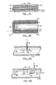
- Fig. 4E is a cross-sectional view of a device for heating or cooling the optical fiber 42 to illustrate an alternative device for heating or cooling the phosphor element 55.
- the entire optical fiber 42 except its very tip, is surrounded by an annular fluid jacket 142.
- Fluid jacket 142 is divided into two concentric sections by a tube 144: inner section 146 and outer section 148 connected at one end. Fluid of a desirable temperature is supplied to the inner section 146 which then flows around the end of tube 144 into outer section 148. Phosphor element 55 is then heated or cooled to the desired temperature of the fluid.
- fiber 42 is protected from external temperature variations.
- tube 144 is a thermal insulator, to reduce heat transmitted between fluids in the two sections.
- Fig. 4F is a perspective view of a section of the optical fiber and the heating coil illustrating another alternative device for heating element 55 and the surrounding environment. Current is supplied through leads 154 to heating coil 152 in order to heat the phosphor element 55 to the desired temperature.
- the two methods described in reference to Figs. 4E, 4F may be combined with infrared light heating by source 44 and filter 56. All such combinations are within the scope of this invention.
- the probe tip may look essentially similar to tip 54 of Fig. 4A except that layer 56 instead of being an optical filter is a material that absorbs RF electromagnetic energy or microwave energy and converts such energy into heat. Element 56 then transfers heat to the phosphor element to heat it.
- the heat transmission equation for solids and fluids is where U, the heat transfer coefficient, may be used to measure the physical properties of solids and fluids.
- the rate of heat transmitted, dq is maintained substantially constant.
- the temperature difference, dt will change.
- the particular temperature difference indicated by a measuring device when matched with the calibrated values, will also indicate the flow rate of the particular fluid.
- the system of Fig. 2, for example, may be so used.
- the system of Fig. 2 may be used to measure the flow rate of the same fluid.
- dq Udt
- dt may be maintained substantially constant and the value of U as an indication of changes in physical properties of the body may be calibrated in terms of the rate of heat dq supplied. This will be discussed in more detail below.
- Figs. 5A, 5B, 5C and 5D are schematic views illustrating how the optical and electronic system of Fig. 2 may be used to measure the flow rate of a fluid.
- fluid 170 flows through a tube 172.
- Probe tip 54 of optical fiber 42 is inserted into the tube.
- Phosphor element 55 is heated or cooled by any one or a combination of the methods described above.
- the heating of element 55 and/or filter 56 in turn heats up a small portion of the fluid 170 that flows past tip 54.
- Portion 170 may also be heated by directly shining light on it.
- the temperature of the fluid that has been heated depends on (1) the temperature of the fluid before heating (2) the heat capacity of the fluid, and (3) the flow rate of fluid 170.
- the flow rate of the liquid 170 may be calibrated against the difference in temperature of element 55 and the unheated fluid. After the calibration, the temperature reading from element 55 will indicate directly the flow rate if the temperature of the unheated fluid (or fluid upstream of the element) is known.
- dt is the difference between the temperature of the phosphor element 55 and the temperature of the fluid before heating.
- the temperature difference, dt, in equation 1 may be maintained constant by varying the rate of heating or cooling supplied will now be discussed in reference to Fig. 5A and Fig. 2. If the flow rate of fluid 170 increases so that the temperature of the element 55 begins to decrease, such decrease changes the emission spectrum as well as the decay time of light emission by the phosphor element. Such changes are detected by the photoreceivers 102,104 which in turn transmits electrical signals to the microprocessor 52 reflecting the decrease in temperature. Microprocessor 52 processes the signals in accordance with a predetermined computer program and supplies signals to driver 48 to increase the rate of heat supplied to tip 54 by source 44 so as to raise the temperature of phosphor element 55 and to maintain it at a constant temperature.
- microprocessor 52 can be programmed in a conventional manner so that the rate of heating supplied to phosphor element 55 will cause its temperature to vary in the same manner in order to maintain a substantially constant dt. It will be evident that the method of maintaining a substantially constant dt may be applied for measuring physical parameters other than flow rates.
- a vortex generating element 174 is placed in the fluid flow 170 as shown in Fig. 5B, vortices 176 will be generated downstream from the generating element 174.
- the frequency of generation of vortices is related to the velocity of the fluid flow. An increase in the velocity of the fluid flow will cause more vortices to be generated. The higher velocity flow associated with the vortices will, as the vortices pass the fiber tip 54, cause momentary drop in the temperature of the probe tip. The frequency of these temperature fluctuations correspond to the frequency of generation of vortices and therefore to the fluid velocity.
- the velocity of the fluid flow can be calibrated in terms of the frequency of temperature variations of element 55.
- Fig. 5C illustrates how this invention can be used for measuring fluid flow by direct thermal dilution.
- a bolus 182 of heated fluid (heated by absorption filter 56) moves toward the end of the fiberoptic tip 54 where the change in temperature is detected.
- the standard way of measuring the time delay and the temperature differences between the heated fluid and non-heated fluid gives the measure of the fluid flow.
- two or more fiberoptics may also be used as illustrated in Fig. 5D.
- the bolus of liquid 182 is heated by direct absorption of radiation by the fluid or by way of heat transferred from tip 54 which is heated by any one or a combination of methods described above.
- the bolus flows downstream to tip 54' of optical fiber 42' and its temperature detected.
- the time delay and temperature difference measurements will indicate the flow rates.
- Using two fiberoptic probes to measure flow rates as in Fig. 5D may be advantageous where the unheated or ambient temperature of the fluid changes.
- one probe which is unheated
- another probe the one shown in Fig. 5A, used to measure the temperature of the heated fluid.
- the calibration curve for flow rate against temperature assuming a constant rate of heat transfer may be shifted by a time varying amount as determined by the variations in the ambient temperature as detected by one of the probes.
- two probes may also be used in the configuration of Fig. 5B for measuring both the temperature changes caused by the vortices and the temperature of the unheated fluid.
- a single fiberoptic probe may be used to perform the same two measurements but at different times by turning the heat source 44 on and off periodically.
- the temperature detected is shown in the graph of Fig. 6.
- the heat source is off, and the temperature T,' indicated by the system of Fig. 2 is the temperature of the.unheated fluid.
- T 2 ' which indicates the temperature of the heated fluid.
- the difference between these two temperatures is dt of equation 1.
- the temperatures of the unheated and heated fluids are T," and T 2 ", respectively.
- the heat source can be turned on and off periodically at a higher frequency to increase the accuracy of the measurement of dt.
- the heat transfer coefficient also varies with the composition of fluid flow.
- foamy air embolism is present in the bloodstream, its presence changes the heat transfer coefficient since air is much lower in heat conductivity than blood.
- the air embolism 192 reaches the probe tip 54, the temperature of phosphor element 55 rises.
- the detection of air bubbles in the bloodstream or fluids to be transported to the vascular system is critical since as little as 10 ml of air can, in some individuals, cause sudden vascular collapse and death.
- the change in heat transfer coefficient of the bloodstream may be detected using the system of Fig. 2 by either keeping the rate of heating or cooling substantially constant or by maintaining substantially constant the temperature difference between phosphor element 54 and the temperature of the thermally unaffected bloodstream. If the rate of heating or cooling is substantially constant, the arrival of air embolism will cause the temperature of element 55 to change. If the temperature difference is maintained constant, the arrival of air embolism will be indicated by a sudden decrease in the rate of heating or cooling which is required to maintain a substantially constant temperature difference. Since the temperature of the bloodstream usually remains rather contant, the temperature of element 55 will frequently be a direct indication of the presence of air embolism unless there is reason to suspect that the temperature of the bloodstream also fluctuates. Thus, in many medical applications the embolism detector of this invention is capable of detecting the presence of air embolism in a fast and convenient manner.
- the heat transfer coefficient also changes for a mixture of two or more gases having different heat capacities and conductivities if their proportions in the mixture change.
- Fig. 8 illustrates how the apparatus of this invention can be used to detect such change in proportions.
- the mixture of gas 202 passes through a chamber 204. If the flow rate of gas 202 is relatively slow at the probe tip 54, then the gas flow in chamber 204 does not significantly affect the temperature and heat transfer between tip 54 and gas 202 inside the chamber. If, for instance, the percentage of the gas component having a higher heat conductivity is increased, heat is carried away by gas 202 from phosphor element 55 at a higher rate than previously. Thus, if the temperature of element 55 has been calibrated against different percentages of the components in the mixture of gases then the temperature of the phosphor element will indicate a certain proportion in the mixture.
- the above described technique is sufficient if the ambient or unheated temperature and pressure of the gas mixture stays essentially unchanged during the measurement. If, however, the ambient temperature and pressure of the gas mixture change during such measurement, it will be necessary to measure such ambient temperature and pressure variations with time by using either a second probe spaced apart from the first probe or by turning the one probe used on and off periodically at an appropriate frequency in substantially the same manner as that described above for measuring flow rates.
- the shape and size and thermal properties of the container defining chamber 204 are not significant provided that chamber 204 defined thereby is large so that at the rate of heating or cooling supplied, the temperature of gas 202 on the whole does not change significantly.
- the same measurement can alternatively be performed by keeping the temperature substantially constant and measuring the gas composition or pressure by the variations in the rate of heating or cooling supplied. If the ambient temperature and/or pressure change during the measurement, either an additional probe should be used to measure such ambient temperature and pressure or that the same measurement can be made by turning the one probe on and off at an appropriate frequency in substantially the same manner as that for the flow rate measurements discussed above.
- Fig. 8 also illustrates how pressure of a gas or other fluid can be measured. If chamber 204 is a vacuum chamber and the gas 202 inside the chamber is being pumped out when element 55 is heated or cooled at a constant rate, then the difference in temperature between element 55 and the unheated gas will rise since there are fewer gas particles to carry away or bring heat to the element. Therefore, if such temperature difference has been calibrated against known pressures of the same gas, then the particular temperature difference will indicate the pressure inside the chamber. If the ambient temperature of the unheated gas changes with time, it will be necessary to measure the ambient temperature repeatedly so that the temperature difference between the element and the unheated gas can be computed. Alternatively, such temperature difference may be kept constant in substantially the same manner as for the flow rate measurement described above, and the pressure of the gas calibrated and measured as a function of the rate of heating or cooling.
- FIGs. 9, 10 illustrate how the levels of fluids can be detected.
- a heavier liquid 224 and a lighter liquid 222 are contained in container 226, with a gas 228 above liquid 224 and probe tips 54, 54' are located as shown. If the fluid level between liquids 222 and 224 changes so that probe tip 54' becomes immersed in liquid 224 or probe tip 54 becomes immersed in liquid 222, then the temperature of phosphor elements 55, 55' would change provided that the two liquids have different heat conductivities.
- a change in temperature of the phosphor element will also be detected.
- a multi-level detector is shown in Fig. 10B.
- the three probe tips 54, 54' and 54" are arranged at different levels within the container 244.
- container 224 is completely filled with liquid 242
- all three probes will indicate the same heat transfer coefficient.
- the temperature of the phosphor element 55' will indicate a different heat transfer coefficient.
- Phosphor element 55' will indicate a similar change in the coefficient as the liquid level falls below probe tip 54'. Such changes will indicate the general location of that fluid level.
- Probe tip 54 is shaped to contact the surface of the sample, the thermal conductivity of which is to be determined.
- the phosphor element 55 being close to the surface of tip 54 in contact with the sample, will have essentially the same temperature as the surface of sample 252 in contact with the probe tip.
- the sample 252 is placed on a heat sink 254 at a known temperature.
- the thermal conductivity of sample 252 is given by where dq is the rate of heat supplied to tip 54, dA is the area of contact between the tip and the sample, dt is the temperature difference between phosphor element 55 and the temperature of heat sink 254 and dx the thickness of sample 252 at the point of contact with the probe tip.
- the thermal conductivity k can be determined if the other quantities are known or measured.
- the apparatus and method of this invention may also be used to differentiate between solids having different heat transfer coefficients even if the solids are not in the shape of sample 252, and are not placed in contact with a heat sink, provided that the solids to be tested are much larger in thermal capacity than tip 54 and that the heat supplied by tip 54 does not significantly change the temperature of most of the solid. Then the geometrical factors and sizes of different solids do not matter and different materials having different conductivities can be differentiated simply by the temperature of phosphor element 55 when tip 54 is in contact with the solids.
- tip 54 and optical fiber 42 be kept at a controlled temperature such as by means of the heating or cooling fluid jacket 142 illustrated in Fig. 4E.
- the sample to be tested is small in heat capacity as compared to the probe tip, it may be desirable to heat or cool the probe tip so that its temperature is close to the temperature of the sample it is testing or measuring.
- the first advantage of temperature conditioning the probe tip is that for measurements involving small objects such as semiconductor devices, the measurement errors are significantly reduced. For example, assume that the sample has the same heat capacity as the probe tip, that initially the sample is at 37,8°C (100°F) and the probe tip is at 21,1°C (70°F). Then when a steady state is reached after the probe tip contacts the sample, the temperatures of the probe tip and the sample converge to 29,4°C (85°F).
- the measurement of the temperature of the sample is off by 8,3°C (15°F) from the correct value 37,8°C (100°F).
- the temperatures of the sample and of the probe tip are shown in Fig. 12A. If, however, the probe tip has been preheated (curve 272) before contacting the sample as illustrated in Fig. 12B, then upon contact the resulting temperature of both the sample and probe tip will be very close to that of the true temperature of the sample before contact.
- the error in temperature measurement without preheating is T err°r (1) as illustrated in Fig. 12A. With preheating, however, the error in temperature measurement has been reduced to T error( 2 ) ⁇
- Figs. 13A and 13B Another advantage in preheating or precooling the probe tip to a temperature close to that of the sample is that much less time will be required to perform the measurement. Such effect is illustrated in Figs. 13A and 13B. As shown in Fig. 13A, considerable time delta t 1 is required to heat or cool the sample so that the temperature of the sample is substantially the same as that of the probe tip. If the probe tip has been preheated or precooled to a temperature (curve 274) close to that of the sample as illustrated in Fig. 13B, the time required to perform the measurement delta t 2 is less than delta t 1 .
Landscapes
- Physics & Mathematics (AREA)
- General Physics & Mathematics (AREA)
- Health & Medical Sciences (AREA)
- Fluid Mechanics (AREA)
- Life Sciences & Earth Sciences (AREA)
- General Health & Medical Sciences (AREA)
- Chemical & Material Sciences (AREA)
- Analytical Chemistry (AREA)
- Pathology (AREA)
- Hematology (AREA)
- Heart & Thoracic Surgery (AREA)
- Biochemistry (AREA)
- Thermal Sciences (AREA)
- Cardiology (AREA)
- Physiology (AREA)
- Biophysics (AREA)
- Engineering & Computer Science (AREA)
- Biomedical Technology (AREA)
- Immunology (AREA)
- Medical Informatics (AREA)
- Molecular Biology (AREA)
- Surgery (AREA)
- Animal Behavior & Ethology (AREA)
- Public Health (AREA)
- Veterinary Medicine (AREA)
- Investigating Or Analyzing Materials Using Thermal Means (AREA)
- Investigating, Analyzing Materials By Fluorescence Or Luminescence (AREA)
Claims (25)
Priority Applications (1)
| Application Number | Priority Date | Filing Date | Title |
|---|---|---|---|
| AT84112257T ATE44614T1 (de) | 1983-10-12 | 1984-10-12 | Verwendungen fuer die waermeflussaenderung einer temperatursonde. |
Applications Claiming Priority (2)
| Application Number | Priority Date | Filing Date | Title |
|---|---|---|---|
| US06/541,384 US4621929A (en) | 1983-10-12 | 1983-10-12 | Fiber optic thermal anemometer |
| US541384 | 1983-10-12 |
Publications (3)
| Publication Number | Publication Date |
|---|---|
| EP0144630A2 EP0144630A2 (de) | 1985-06-19 |
| EP0144630A3 EP0144630A3 (en) | 1985-07-10 |
| EP0144630B1 true EP0144630B1 (de) | 1989-07-12 |
Family
ID=24159361
Family Applications (1)
| Application Number | Title | Priority Date | Filing Date |
|---|---|---|---|
| EP84112257A Expired EP0144630B1 (de) | 1983-10-12 | 1984-10-12 | Verwendungen für die Wärmeflussänderung einer Temperatursonde |
Country Status (6)
| Country | Link |
|---|---|
| US (1) | US4621929A (de) |
| EP (1) | EP0144630B1 (de) |
| JP (1) | JPS6098345A (de) |
| AT (1) | ATE44614T1 (de) |
| CA (1) | CA1230240A (de) |
| DE (1) | DE3478951D1 (de) |
Families Citing this family (67)
| Publication number | Priority date | Publication date | Assignee | Title |
|---|---|---|---|---|
| GB2170593B (en) * | 1985-02-01 | 1988-09-14 | Central Electr Generat Board | Temperature measurement |
| US4883354A (en) * | 1985-10-25 | 1989-11-28 | Luxtron Corporation | Fiberoptic sensing of temperature and/or other physical parameters |
| US4900933A (en) * | 1986-09-08 | 1990-02-13 | C. R. Bard, Inc. | Excitation and detection apparatus for remote sensor connected by optical fiber |
| US5085073A (en) * | 1988-01-22 | 1992-02-04 | The United States Of America As Represented By The Administator Of The United States National Aeronautics And Space Administration | Thermal remote anemometer system |
| US4986671A (en) * | 1989-04-12 | 1991-01-22 | Luxtron Corporation | Three-parameter optical fiber sensor and system |
| US5026170A (en) * | 1989-06-07 | 1991-06-25 | The United States Of America As Represented By The United States Department Of Energy | Optical heat flux gauge |
| US5005984A (en) * | 1989-06-07 | 1991-04-09 | The United States Of America As Represented By The United States Department Of Energy | Optical heat flux gauge |
| US5047626A (en) * | 1990-01-03 | 1991-09-10 | The United States Of America As Represented By The Secretary Of The Navy | Optical fiber sensor for measuring physical properties of liquids |
| US5115127A (en) * | 1990-01-03 | 1992-05-19 | The United States Of America As Represented By The Secretary Of The Navy | Optical fiber sensor for measuring physical properties of fluids |
| US5237523A (en) * | 1990-07-25 | 1993-08-17 | Honeywell Inc. | Flowmeter fluid composition and temperature correction |
| US5255980A (en) * | 1990-10-18 | 1993-10-26 | Rosemount Inc. | Black body TRD temperature sensor |
| DE69129104T2 (de) * | 1990-12-14 | 1998-11-19 | Anritsu Corp | Fühlvorrichtung zur messung des charakteristischen wertes eines zu messenden elementes unter verwendung der veränderungen des thermischen widerstands |
| US5273359A (en) * | 1992-04-03 | 1993-12-28 | The United States Of America As Represented By The United States Department Of Energy | Remote high-temperature insulatorless heat-flux gauge |
| US5354990A (en) * | 1993-05-18 | 1994-10-11 | Exxon Research And Engineering Co. | In-situ localized tracer injection/fiber optic detection for measurement of flow distributions in fixed bed reactors |
| US5520190A (en) * | 1994-10-31 | 1996-05-28 | Ventritex, Inc. | Cardiac blood flow sensor and method |
| FR2728071A1 (fr) * | 1994-12-07 | 1996-06-14 | Auxitrol Sa | Debitmetre massique a fil chaud |
| WO1997010748A1 (en) | 1995-09-20 | 1997-03-27 | Texas Heart Institute | Detecting thermal discrepancies in vessel walls |
| US5954659A (en) * | 1996-02-16 | 1999-09-21 | Curley; Michael G. | Method and apparatus for invasively measuring cardiac output by detecting temperature differences of blood heated by radiation |
| US5673342A (en) * | 1996-05-28 | 1997-09-30 | Lucent Technologies Inc. | Communication system comprising a low cost optical filter |
| JPH10117424A (ja) * | 1996-08-23 | 1998-05-06 | Sumitomo Electric Ind Ltd | 電力ケーブルの埋設深度測定方法 |
| JPH10197398A (ja) * | 1996-11-18 | 1998-07-31 | Ono Sokki Co Ltd | 光ファイバーの環境可変装置、その摘出装置及びその摘出システム |
| NL1010369C2 (nl) * | 1998-05-01 | 1999-12-21 | Maasland Nv | Werkwijze alsmede een inrchting voor het akoestisch bewaken van het verloop van een proces, zoals een melkproces. |
| US6185446B1 (en) * | 1998-08-21 | 2001-02-06 | William F. Carlsen, Jr. | Method and apparatus for monitoring the breathing of a patient during magnetic resonance imaging |
| AU5791999A (en) * | 1998-08-25 | 2000-03-14 | Baker Hughes Incorporated | Method of using a heater with a fiber optic string in a wellbore |
| US6769805B2 (en) | 1998-08-25 | 2004-08-03 | Sensor Highway Limited | Method of using a heater with a fiber optic string in a wellbore |
| US6840671B2 (en) * | 2001-04-09 | 2005-01-11 | William R. Barron, Jr. | System and method for non-contact temperature sensing |
| US7080940B2 (en) * | 2001-04-20 | 2006-07-25 | Luxtron Corporation | In situ optical surface temperature measuring techniques and devices |
| US6796710B2 (en) * | 2001-06-08 | 2004-09-28 | Ethicon Endo-Surgery, Inc. | System and method of measuring and controlling temperature of optical fiber tip in a laser system |
| US6804622B2 (en) * | 2001-09-04 | 2004-10-12 | General Electric Company | Method and apparatus for non-destructive thermal inspection |
| GB2401430B (en) * | 2003-04-23 | 2005-09-21 | Sensor Highway Ltd | Fluid flow measurement |
| JP2004363559A (ja) * | 2003-05-14 | 2004-12-24 | Canon Inc | 光学部材保持装置 |
| US20040252748A1 (en) * | 2003-06-13 | 2004-12-16 | Gleitman Daniel D. | Fiber optic sensing systems and methods |
| US7168850B2 (en) * | 2004-03-30 | 2007-01-30 | Yamatake Corporation | Mirror surface state detection device and moisture detection device |
| KR100682032B1 (ko) * | 2005-10-31 | 2007-02-12 | 포항공과대학교 산학협력단 | 측정 장치 |
| US20070171958A1 (en) * | 2006-01-23 | 2007-07-26 | Anh Hoang | Electrical device measurement probes |
| US20080069180A1 (en) * | 2006-09-19 | 2008-03-20 | Derek Djeu | Fiber optic temperature sensing system using a hemispherical phosphor |
| US7742153B2 (en) * | 2006-10-02 | 2010-06-22 | University Of Utah Research Foundation | Miniature opto-mechanical anemometer |
| US7651261B2 (en) * | 2007-07-10 | 2010-01-26 | General Electric Company | System and method for thermal inspection of parts |
| US20090297336A1 (en) * | 2007-08-21 | 2009-12-03 | General Electric Company | Online systems and methods for thermal inspection of parts |
| US20090074027A1 (en) * | 2007-09-18 | 2009-03-19 | Vatell Corporation | Heat flux sensor incorporating light conveyance |
| US7665891B1 (en) * | 2007-09-20 | 2010-02-23 | The United States Of America As Represented By The Administrator Of The National Aeronautics And Space Administration | Differential temperature sensor system and method |
| US8197417B2 (en) * | 2008-03-04 | 2012-06-12 | Medical Graphics Corporation | Metabolic analyzer transducer |
| US7909507B2 (en) * | 2008-04-11 | 2011-03-22 | General Electric Company | Thermal inspection system and method |
| US8201997B1 (en) * | 2008-05-29 | 2012-06-19 | Ipitek, Inc. | Imaging temperature sensing system |
| US8864669B2 (en) | 2008-12-29 | 2014-10-21 | Perseus-Biomed Inc. | Method and system for tissue imaging and analysis |
| US8882672B2 (en) | 2008-12-29 | 2014-11-11 | Perseus-Biomed Inc. | Method and system for tissue imaging and analysis |
| US8870772B2 (en) * | 2008-12-29 | 2014-10-28 | Perseus-Biomed Inc. | Method and system for tissue recognition |
| US8244488B2 (en) * | 2009-11-25 | 2012-08-14 | General Electric Company | Thermal inspection systems |
| US20110164653A1 (en) * | 2010-01-07 | 2011-07-07 | General Electric Company | Thermal inspection system and method incorporating external flow |
| US8571813B2 (en) * | 2010-03-16 | 2013-10-29 | Siemens Energy, Inc. | Fiber optic sensor system for detecting surface wear |
| EP2591326A1 (de) * | 2010-07-07 | 2013-05-15 | ABB Research Ltd. | Faseroptisches doppelbrechungsthermometer und herstellungsverfahren dafür |
| CN102135511B (zh) * | 2010-12-29 | 2013-08-28 | 浙江银轮机械股份有限公司 | 一种板翅式换热器翅片表面传热性能的测试方法及装置 |
| JP5961688B2 (ja) * | 2011-06-01 | 2016-08-02 | コーニンクレッカ フィリップス エヌ ヴェKoninklijke Philips N.V. | 血流分布測定システム及び方法 |
| US9557344B2 (en) | 2011-07-12 | 2017-01-31 | The Hong Kong Polytechnic University | Sensor for measuring flow speed of a fluid |
| US10463259B2 (en) | 2011-10-28 | 2019-11-05 | Three Rivers Cardiovascular Systems Inc. | System and apparatus comprising a multi-sensor catheter for right heart and pulmonary artery catheterization |
| WO2013061280A1 (en) | 2011-10-28 | 2013-05-02 | Hemodynamix Medical Systems Inc. | Fluid temperature and flow sensor apparatus and system for cardiovascular and other medical applications |
| US9151152B2 (en) * | 2012-06-20 | 2015-10-06 | Schlumberger Technology Corporation | Thermal optical fluid composition detection |
| US9696091B2 (en) * | 2012-07-13 | 2017-07-04 | Adc Acquisition Company | Superimposed zones process heating |
| FR3012881B1 (fr) | 2013-11-06 | 2015-11-27 | Commissariat Energie Atomique | Capteur de pression a resonateur electromagnetique |
| US10634536B2 (en) * | 2013-12-23 | 2020-04-28 | Exxonmobil Research And Engineering Company | Method and system for multi-phase flow measurement |
| EP3033490A1 (de) * | 2013-12-27 | 2016-06-22 | Halliburton Energy Services, Inc. | Flussprofilmessung für ein mehrphasiges fluid |
| US10722175B2 (en) | 2014-07-13 | 2020-07-28 | Hemocath Ltd. | System and apparatus comprising a multisensor guidewire for use in interventional cardiology |
| EP3268704A4 (de) * | 2015-03-10 | 2018-11-14 | Thermobar AB | Steuerungsvorrichtung und wassertank für rinder- und pferdetränke |
| US11272847B2 (en) | 2016-10-14 | 2022-03-15 | Hemocath Ltd. | System and apparatus comprising a multi-sensor catheter for right heart and pulmonary artery catheterization |
| EP4041071A4 (de) | 2019-09-30 | 2023-10-18 | HemoCath Ltd. | Katheter mit mehreren sensoren für rechtsherz- und pulmonalarterienkathetisierung |
| CN111189547B (zh) * | 2020-03-11 | 2021-04-09 | 山东大学 | 一种可替代铣削刀具测温的装置及方法 |
| CN111678615A (zh) * | 2020-05-19 | 2020-09-18 | 电子科技大学 | 一种温度检测的光纤光栅液位传感器 |
Family Cites Families (34)
| Publication number | Priority date | Publication date | Assignee | Title |
|---|---|---|---|---|
| US673075A (en) * | 1900-02-01 | 1901-04-30 | Maurice Ernest Douane | Refrigerating apparatus. |
| US3251228A (en) * | 1963-07-12 | 1966-05-17 | Stewart Warner Corp | Temperature sensitive pressure system |
| US3580081A (en) * | 1969-09-10 | 1971-05-25 | Veeco Instr Inc | Vacuum gauge |
| US3797310A (en) * | 1972-02-28 | 1974-03-19 | Steel Corp | Temperature sensing device |
| US3917945A (en) * | 1973-06-21 | 1975-11-04 | Hayashi Katsuhiki | Method and apparatus for detecting the degree of contamination of waste water |
| US4016761A (en) * | 1974-04-18 | 1977-04-12 | The United States Of America As Represented By The Secretary Of The Navy | Optical temperature probe |
| DE2445804A1 (de) * | 1974-09-25 | 1976-04-15 | Siemens Ag | Verfahren zur messung eines elektrischen parameters, insbesondere des temperaturkoeffizienten von halbleiter-temperaturfuehlern |
| US4140393A (en) * | 1976-02-23 | 1979-02-20 | University Of Arizona | Birefringent crystal thermometer |
| DE2742556A1 (de) * | 1976-09-22 | 1978-03-23 | Matsushita Electric Ind Co Ltd | Verfahren zum ablesen eines thermolumineszenten dosimeters |
| US4075493A (en) * | 1976-12-16 | 1978-02-21 | Ronald Alves | Optical temperature measurement technique utilizing phosphors |
| US4136566A (en) * | 1977-06-24 | 1979-01-30 | University Of Utah | Semiconductor temperature sensor |
| US4179927A (en) * | 1977-09-28 | 1979-12-25 | Electric Power Research Institute, Inc. | Temperature sensing device |
| US4215275A (en) * | 1977-12-07 | 1980-07-29 | Luxtron Corporation | Optical temperature measurement technique utilizing phosphors |
| US4223226A (en) * | 1978-07-26 | 1980-09-16 | Rockwell International Corporation | Fiber optic temperature sensor |
| US4403143A (en) * | 1978-11-03 | 1983-09-06 | Research Energy Of Ohio, Inc. | Detonating cord and continuity verification system |
| SE414672B (sv) * | 1978-11-16 | 1980-08-11 | Asea Ab | Fiberoptiskt don for metning av fysikaliska storheter sasom kraft, tojning, tryck, acceleration och temperatur |
| SE420769B (sv) * | 1978-12-05 | 1981-10-26 | Asea Ab | Fiberoptiskt temperaturmetdon av pyrometertyp |
| US4344315A (en) * | 1978-12-29 | 1982-08-17 | Ceres Electronics Corporation | Method and device for distinguishing material by thermal conductivity |
| US4355910A (en) * | 1979-01-22 | 1982-10-26 | Rockwell International Corporation | Method and apparatus for an optical sensor utilizing semiconductor filters |
| JPS55149810A (en) * | 1979-05-11 | 1980-11-21 | Nissan Motor Co Ltd | Flow measuring apparatus |
| DE2929427A1 (de) * | 1979-07-20 | 1981-02-05 | Bosch Gmbh Robert | Einrichtung zur luftmassenmessung im luftansaugrohr einer brennkraftmaschine |
| US4295739A (en) * | 1979-08-30 | 1981-10-20 | United Technologies Corporation | Fiber optic temperature sensor |
| US4245507A (en) * | 1979-09-10 | 1981-01-20 | Samulski Thaddeus V | Temperature probe |
| SE431259B (sv) * | 1979-10-10 | 1984-01-23 | Asea Ab | Fiberoptisk temperaturgivare baserad pa fotoluminiscens hos ett fast material |
| CH639485A5 (fr) * | 1980-01-09 | 1983-11-15 | Ciposa Sa | Procede et dispositif de mesure optique de temperature. |
| US4458709A (en) * | 1980-03-27 | 1984-07-10 | Binks Manufacturing Company | Method and apparatus for measuring and controlling fluid flow rates |
| US4373768A (en) * | 1980-03-31 | 1983-02-15 | Raychem Corporation | Thermostatic fiber optic waveguides |
| JPS56142414A (en) * | 1980-04-09 | 1981-11-06 | Nippon Soken Inc | Device for measuring gas flow quantity |
| SE422111B (sv) * | 1980-06-23 | 1982-02-15 | Asea Ab | Fiberoptiskt kopplat metdon |
| US4362057A (en) * | 1980-10-10 | 1982-12-07 | Electric Power Research Institute, Inc. | Optical fiber temperature sensor |
| US4374328A (en) * | 1981-04-27 | 1983-02-15 | Gould Inc. | Photoluminescent indicator |
| DE3202089C2 (de) * | 1982-01-23 | 1985-01-17 | Fa. Carl Zeiss, 7920 Heidenheim | Faseroptischer Temperatursensor |
| SE435966B (sv) * | 1982-02-02 | 1984-10-29 | Asea Ab | Fiberoptiskt metdon |
| US4435978A (en) * | 1982-09-07 | 1984-03-13 | Glatz John J | Hot wire anemometer flow meter |
-
1983
- 1983-10-12 US US06/541,384 patent/US4621929A/en not_active Expired - Fee Related
-
1984
- 1984-10-11 JP JP59214077A patent/JPS6098345A/ja active Pending
- 1984-10-12 CA CA000465344A patent/CA1230240A/en not_active Expired
- 1984-10-12 EP EP84112257A patent/EP0144630B1/de not_active Expired
- 1984-10-12 AT AT84112257T patent/ATE44614T1/de not_active IP Right Cessation
- 1984-10-12 DE DE8484112257T patent/DE3478951D1/de not_active Expired
Also Published As
| Publication number | Publication date |
|---|---|
| DE3478951D1 (en) | 1989-08-17 |
| EP0144630A3 (en) | 1985-07-10 |
| ATE44614T1 (de) | 1989-07-15 |
| JPS6098345A (ja) | 1985-06-01 |
| EP0144630A2 (de) | 1985-06-19 |
| CA1230240A (en) | 1987-12-15 |
| US4621929A (en) | 1986-11-11 |
Similar Documents
| Publication | Publication Date | Title |
|---|---|---|
| EP0144630B1 (de) | Verwendungen für die Wärmeflussänderung einer Temperatursonde | |
| US4986671A (en) | Three-parameter optical fiber sensor and system | |
| US4851817A (en) | Fiber optic probe system | |
| US5183338A (en) | Temperature measurement with combined photo-luminescent and black body sensing techniques | |
| Smits et al. | Constant temperature hot-wire anemometer practice in supersonic flows: Part l: The normal wire | |
| US5004913A (en) | Remote measurement of physical variables with fiber optic systems - methods, materials and devices | |
| CA1292368C (en) | Fiberoptic sensing of temperature and/or other physical parameters | |
| US5141331A (en) | Ultrasonic temperature measurement and uses in optical spectroscopy and calorimetry | |
| US4374328A (en) | Photoluminescent indicator | |
| US5073720A (en) | Liquid level and volume measurement device | |
| JPH06507022A (ja) | 光ルミネッセンスと黒体検出技術を組み合わせて用いた温度測定 | |
| US20030206573A1 (en) | In situ optical surface temperature measuring techniques and devices | |
| US5038620A (en) | Coriolis mass flow meter | |
| US5020380A (en) | Mass flow operating by the coriolis principle | |
| US6118134A (en) | Optical mass gauge sensor having an energy per unit area of illumination detection | |
| US5090818A (en) | Fiber optic systems for sensing temperature and other physical variables | |
| JPS61145435A (ja) | 光ファイバプローブ及びその製造方法 | |
| US5208650A (en) | Thermal dilation fiber optical flow sensor | |
| NO823063L (no) | Fiberkobler-omsetter | |
| US5367175A (en) | Method of measuring liquid level with a thermal interface detection | |
| US3332285A (en) | Fast precision temperature sensing thermocouple probe | |
| US5831268A (en) | Sensing device for reflective clear material using infrared LED | |
| JP3081251B2 (ja) | 析出点計及び析出点測定方法 | |
| US7104683B2 (en) | Thermally compensated fluorescence decay rate temperature sensor and method of use | |
| US5606125A (en) | Material level-interface control system |
Legal Events
| Date | Code | Title | Description |
|---|---|---|---|
| PUAI | Public reference made under article 153(3) epc to a published international application that has entered the european phase |
Free format text: ORIGINAL CODE: 0009012 |
|
| PUAL | Search report despatched |
Free format text: ORIGINAL CODE: 0009013 |
|
| 17P | Request for examination filed |
Effective date: 19841012 |
|
| AK | Designated contracting states |
Designated state(s): AT BE CH DE FR GB IT LI LU NL SE |
|
| AK | Designated contracting states |
Designated state(s): AT BE CH DE FR GB IT LI LU NL SE |
|
| 17Q | First examination report despatched |
Effective date: 19870901 |
|
| GRAA | (expected) grant |
Free format text: ORIGINAL CODE: 0009210 |
|
| AK | Designated contracting states |
Kind code of ref document: B1 Designated state(s): AT BE CH DE FR GB IT LI LU NL SE |
|
| PG25 | Lapsed in a contracting state [announced via postgrant information from national office to epo] |
Ref country code: SE Free format text: THE PATENT HAS BEEN ANNULLED BY A DECISION OF A NATIONAL AUTHORITY Effective date: 19890712 Ref country code: NL Effective date: 19890712 Ref country code: LI Effective date: 19890712 Ref country code: IT Free format text: LAPSE BECAUSE OF FAILURE TO SUBMIT A TRANSLATION OF THE DESCRIPTION OR TO PAY THE FEE WITHIN THE PRESCRIBED TIME-LIMIT;WARNING: LAPSES OF ITALIAN PATENTS WITH EFFECTIVE DATE BEFORE 2007 MAY HAVE OCCURRED AT ANY TIME BEFORE 2007. THE CORRECT EFFECTIVE DATE MAY BE DIFFERENT FROM THE ONE RECORDED. Effective date: 19890712 Ref country code: CH Effective date: 19890712 Ref country code: BE Effective date: 19890712 Ref country code: AT Effective date: 19890712 |
|
| REF | Corresponds to: |
Ref document number: 44614 Country of ref document: AT Date of ref document: 19890715 Kind code of ref document: T |
|
| REF | Corresponds to: |
Ref document number: 3478951 Country of ref document: DE Date of ref document: 19890817 |
|
| ET | Fr: translation filed | ||
| PG25 | Lapsed in a contracting state [announced via postgrant information from national office to epo] |
Ref country code: LU Free format text: LAPSE BECAUSE OF NON-PAYMENT OF DUE FEES Effective date: 19891031 |
|
| REG | Reference to a national code |
Ref country code: CH Ref legal event code: PL |
|
| NLV1 | Nl: lapsed or annulled due to failure to fulfill the requirements of art. 29p and 29m of the patents act | ||
| PLBE | No opposition filed within time limit |
Free format text: ORIGINAL CODE: 0009261 |
|
| STAA | Information on the status of an ep patent application or granted ep patent |
Free format text: STATUS: NO OPPOSITION FILED WITHIN TIME LIMIT |
|
| 26N | No opposition filed | ||
| REG | Reference to a national code |
Ref country code: FR Ref legal event code: ST |
|
| REG | Reference to a national code |
Ref country code: FR Ref legal event code: AR |
|
| REG | Reference to a national code |
Ref country code: FR Ref legal event code: BR |
|
| PGFP | Annual fee paid to national office [announced via postgrant information from national office to epo] |
Ref country code: FR Payment date: 20000919 Year of fee payment: 17 |
|
| PGFP | Annual fee paid to national office [announced via postgrant information from national office to epo] |
Ref country code: DE Payment date: 20000920 Year of fee payment: 17 |
|
| PGFP | Annual fee paid to national office [announced via postgrant information from national office to epo] |
Ref country code: GB Payment date: 20000921 Year of fee payment: 17 |
|
| PG25 | Lapsed in a contracting state [announced via postgrant information from national office to epo] |
Ref country code: GB Free format text: LAPSE BECAUSE OF NON-PAYMENT OF DUE FEES Effective date: 20011012 |
|
| REG | Reference to a national code |
Ref country code: GB Ref legal event code: IF02 |
|
| GBPC | Gb: european patent ceased through non-payment of renewal fee |
Effective date: 20011012 |
|
| PG25 | Lapsed in a contracting state [announced via postgrant information from national office to epo] |
Ref country code: DE Free format text: LAPSE BECAUSE OF NON-PAYMENT OF DUE FEES Effective date: 20020702 |
|
| REG | Reference to a national code |
Ref country code: FR Ref legal event code: ST |
|
| PG25 | Lapsed in a contracting state [announced via postgrant information from national office to epo] |
Ref country code: FR Free format text: LAPSE BECAUSE OF NON-PAYMENT OF DUE FEES Effective date: 20011031 |