EP0144625B1 - Injection device - Google Patents
Injection device Download PDFInfo
- Publication number
- EP0144625B1 EP0144625B1 EP84112180A EP84112180A EP0144625B1 EP 0144625 B1 EP0144625 B1 EP 0144625B1 EP 84112180 A EP84112180 A EP 84112180A EP 84112180 A EP84112180 A EP 84112180A EP 0144625 B1 EP0144625 B1 EP 0144625B1
- Authority
- EP
- European Patent Office
- Prior art keywords
- injection
- casing
- syringe
- sleeve
- supported
- Prior art date
- Legal status (The legal status is an assumption and is not a legal conclusion. Google has not performed a legal analysis and makes no representation as to the accuracy of the status listed.)
- Expired
Links
Images

Classifications
-
- A—HUMAN NECESSITIES
- A61—MEDICAL OR VETERINARY SCIENCE; HYGIENE
- A61M—DEVICES FOR INTRODUCING MEDIA INTO, OR ONTO, THE BODY; DEVICES FOR TRANSDUCING BODY MEDIA OR FOR TAKING MEDIA FROM THE BODY; DEVICES FOR PRODUCING OR ENDING SLEEP OR STUPOR
- A61M5/00—Devices for bringing media into the body in a subcutaneous, intra-vascular or intramuscular way; Accessories therefor, e.g. filling or cleaning devices, arm-rests
- A61M5/178—Syringes
- A61M5/20—Automatic syringes, e.g. with automatically actuated piston rod, with automatic needle injection, filling automatically
- A61M5/2033—Spring-loaded one-shot injectors with or without automatic needle insertion
-
- A—HUMAN NECESSITIES
- A61—MEDICAL OR VETERINARY SCIENCE; HYGIENE
- A61M—DEVICES FOR INTRODUCING MEDIA INTO, OR ONTO, THE BODY; DEVICES FOR TRANSDUCING BODY MEDIA OR FOR TAKING MEDIA FROM THE BODY; DEVICES FOR PRODUCING OR ENDING SLEEP OR STUPOR
- A61M5/00—Devices for bringing media into the body in a subcutaneous, intra-vascular or intramuscular way; Accessories therefor, e.g. filling or cleaning devices, arm-rests
- A61M5/178—Syringes
- A61M5/20—Automatic syringes, e.g. with automatically actuated piston rod, with automatic needle injection, filling automatically
- A61M2005/206—With automatic needle insertion
-
- A—HUMAN NECESSITIES
- A61—MEDICAL OR VETERINARY SCIENCE; HYGIENE
- A61M—DEVICES FOR INTRODUCING MEDIA INTO, OR ONTO, THE BODY; DEVICES FOR TRANSDUCING BODY MEDIA OR FOR TAKING MEDIA FROM THE BODY; DEVICES FOR PRODUCING OR ENDING SLEEP OR STUPOR
- A61M5/00—Devices for bringing media into the body in a subcutaneous, intra-vascular or intramuscular way; Accessories therefor, e.g. filling or cleaning devices, arm-rests
- A61M5/178—Syringes
- A61M5/20—Automatic syringes, e.g. with automatically actuated piston rod, with automatic needle injection, filling automatically
- A61M2005/2073—Automatic syringes, e.g. with automatically actuated piston rod, with automatic needle injection, filling automatically preventing premature release, e.g. by making use of a safety lock
-
- A—HUMAN NECESSITIES
- A61—MEDICAL OR VETERINARY SCIENCE; HYGIENE
- A61M—DEVICES FOR INTRODUCING MEDIA INTO, OR ONTO, THE BODY; DEVICES FOR TRANSDUCING BODY MEDIA OR FOR TAKING MEDIA FROM THE BODY; DEVICES FOR PRODUCING OR ENDING SLEEP OR STUPOR
- A61M5/00—Devices for bringing media into the body in a subcutaneous, intra-vascular or intramuscular way; Accessories therefor, e.g. filling or cleaning devices, arm-rests
- A61M5/178—Syringes
- A61M5/24—Ampoule syringes, i.e. syringes with needle for use in combination with replaceable ampoules or carpules, e.g. automatic
- A61M5/2422—Ampoule syringes, i.e. syringes with needle for use in combination with replaceable ampoules or carpules, e.g. automatic using emptying means to expel or eject media, e.g. pistons, deformation of the ampoule, or telescoping of the ampoule
- A61M5/2429—Ampoule syringes, i.e. syringes with needle for use in combination with replaceable ampoules or carpules, e.g. automatic using emptying means to expel or eject media, e.g. pistons, deformation of the ampoule, or telescoping of the ampoule by telescoping of ampoules or carpules with the syringe body
Definitions
- the invention relates to an injection device with an injection syringe, which is accommodated coaxially in a circular cylindrical housing, the housing being closed on both sides by covers, from which covers the one arranged at the front end of the housing has a central opening for the injection cannula, which has a plug which can be penetrated by the injection cannula is locked,
- a spring is provided as the driver, which is compressed and supported, on the one hand, on the injection syringe and, on the other hand, on the housing,
- a coaxial bolt is provided for the lock, which has a recess, at least one locking ball fitting into the recess,
- the locking ball is supported forwardly on a support on the housing and outwardly on a sleeve
- the object of the invention is a
- the invention is characterized in that the bolt is attached to the rear end of the syringe,
- the rear cover is provided as a handle and the cuff is slidably mounted to move forward.
- the syringe hooks into the ring groove behind the locking balls and is thus held back against the force of the tensioned spring.
- This lock cannot be released accidentally or automatically due to vibrations, it can only be released by depressing the handle.
- the injection device is characterized by a simple, clear structure using fewer simple components and ensures reliable operation.
- the spring for the injector also provides a desirable back pressure for the handle.
- the handle is additionally secured against inadvertent actuation by a configuration according to claim 4.
- a preferred embodiment according to claim 9 makes it possible to ensure with particularly simple means that first the injection cannula and only then the liquid is expelled.
- 1 denotes a circular cylindrical housing which is closed at the front end by a cover 2 and at the rear end by a cover serving as a handle 3. Each cover is secured by a catch and can be removed while overcoming the catch.
- the catch 57 belongs to the cover 2, a bead 47 on the housing and a constriction 48 on the handle 3 form the catch for the rear cover.
- An injection syringe 5 is arranged coaxially to the axis 4 within the housing 1.
- This injection syringe 5 consists of a syringe body 6 which has a circular cylindrical, coaxial liquid tank 7.
- the liquid tank 7 is open to the front, that is to the bottom in FIGS. 1 and 2.
- the opening 8 in question is circular.
- the liquid tank 7 is closed by a bottom 9.
- a circular cylindrical piston 10 which is inserted from the front and has a needle holder 11 on its front end, onto which a rear cap 12 of an injection cannula 13 is attached.
- the piston 10 has a channel 14 coaxial with the axis 4, which leads from the interior of the liquid tank 7 to the injection cannula and is sealed with two sealing beads 43, 44.
- the injection cannula 13 is with its beveled tip 16 in a plug 17 made of sealing material.
- the plug 17 closes the front opening 18 of the injection cannula.
- the plug 17 also closes a central opening 19 which is provided in the cover 2.
- the material from which the plug is made is sufficiently sealing but so soft that it can be pierced by the injection cannula which extends forward.
- a bolt 20 is formed coaxially to the axis 4, which has an annular groove 21. This bolt is guided in a central opening 23 of a support 22 arranged fixed to the housing.
- a sleeve which has a base plate 25 with a central opening 26 through which the pin 20 is inserted.
- a helical spring 28 is compressed, which surrounds the syringe body 6 coaxially to the axis 4 and is supported at the front on a collar 29 of the syringe body 6.
- the collar 29 forms with the inner wall of the housing 1 a guide for the longitudinal movement of the syringe body 6 in the direction of the axis 4.
- the sleeve 24 has two diametrically opposed wings 32, 33 and fits with its base plate 25 and these wings slidably in the direction of the axis 4 in the housing 1. On the inside of the two wings 32, 33, a fitting channel 34, 35 is inserted .
- the fitting channels are diametrically opposed to one another and extend parallel to axis 4.
- the locking balls protrude into the fitting channels 34, 35, which extend from the upper end of the sleeve 24 to the height of the locking balls 36, 37 in the locked position according to FIG.
- the locking balls prevent the bolt 20 from evading to the front following the spring force of the tensioned spring 28. Rather, they hold the syringe 5 securely in the locked position shown in FIG. 1 and, together with the sleeve 24 and the bolt 20, form a lock, generally designated 30.
- the handle 3 designed as a cover protrudes from the top of the housing 1 and is displaceable in the axial direction 4 in the housing 1.
- the handle 3 is prevented from doing so by inwardly projecting stops 47, 63 of the housing and corresponding projections 48, 65 on the handle dodge back.
- the rear ends of the fitting channels 34, 35 are extensions 54, 55.
- a corresponding extension 56 is provided at the opposite forward end of the handle 3.
- the extensions 54, 55 offer 3 space for the locking balls when the handle is pushed forward so that they can emerge from the annular groove 21.
- a protective cap 38 is placed over the handle 3 and is secured with a catch 39 to the rear end of the housing.
- a retaining clip is designated, which allows the injection device in preparation, which is about the size of a coarse fountain pen, to be inserted into a jacket pocket and secured against loss, like a fountain pen.
- the liquid tank 7 and the channel 14 and the interior of the injection cannula 13 are filled with injection liquid 40.
- the protective cap 38 is pulled off and the housing 1 with the front end face 46 of the front cover 2 is placed on the skin - in an emergency with the wardrobe interposed and then the handle 3 is pushed forward in the direction of arrow 42.
- the sleeve 24 is pushed a little downward against the force of the spring 28 into the position shown in FIG. 2, in which the locking balls 36, 37 can escape outward from the annular groove 21 into the annular extensions 54, 55.
- the syringe 5 is no longer held and driven forward by the spring 28.
- the injection cannula 13 first pierces the plug 17 and emerges from the opening 19 and penetrates the muscle meat through the skin until the placement cap 12 strikes the cover 2 in a conical opening 45 of the cover 2.
- the piston 10 can no longer move forward. However, since the syringe body 6 is driven further forward, the liquid 40 is now expelled through the injection cannula 13 under the force of the spring 28 and injected into the muscle meat until the syringe body strikes the piston 10 in the one shown in FIG. 2
- the syringe 5 is pressed backwards while simultaneously tensioning the spring 28, beyond the provision. In this position, the locking balls 36, 37 can enter their locking position from above, while the injection device is held with the rear end upward.
- the device is assembled in a corresponding manner during initial installation. If necessary, the handle 3 can be removed in order to securely insert the locking balls into the fitting channels 34, 35. You can now disinfect the emptied and cleaned injection syringe 5 with the plunger 10 pulled out. Then the interior 15 of the liquid tank is filled with injection liquid 40 and the piston 10 is inserted, at the same time the device is held with the front end upwards, so that an air bubble-free filling including the injection cannula is ensured. Then the lid 2 is put on and the plug 17 is injected. The injection device is now ready again.
- the exemplary embodiment according to FIGS. 5 to 7 is very similar to the exemplary embodiment according to FIGS. 1 to 4. Only the differences are mainly described below and, if not described, the exemplary embodiment according to FIGS. 5 to 7 is designed in exactly the same way as the exemplary embodiment according to FIGS. 1 to 4 and is also operated in the same way.
- 101 denotes the tubular housing, which is closed at the front by an integrally formed cover 102 and can be closed at the rear by a cover serving as a handle 103.
- an injection syringe is designated, the syringe body with 106, the liquid tank with 107, the piston with 110, the needle holder with 111, the cap with 112 and the injection needle with 113.
- the piston 110 engages with a bead 172 in an annular groove 173 of the syringe body 106 for sealing.
- the piston has a recess 175 at the front which surrounds the needle holder 111 in order to spring the needle holder and to relieve the piston of the weight.
- a collar at the front end of the syringe body 106 is designated by 129, on which a helical spring 128 which is compressed according to FIG. 5 is supported.
- a bolt 120 is fastened coaxially to the axis 104 of the housing and has two elongated recesses 160, 161 diametrically opposite one another, which extend parallel to the axis 104 and fit into the two locking balls 136, 137.
- a cuff is designated by 124, on the end face 127 of which the helical spring 128 is supported according to FIG.
- the cuff 124 in turn is supported on the rear on the handle 103, which in turn is supported on the back with two diametrically opposite projections 148, 165 on two diametrically opposite stops 147, 163 fixed to the housing.
- the handle 103 can be released in the manner of a bayonet lock by rotating it in the housing by 90 degrees with respect to the axis 104. Then the projections 148, 165 are free from the stops 147, 163 and find space in channels of the housing which are not visible in the drawing, so that in the position rotated by 90 degrees relative to the drawing, the handles are pulled up out of the housing can.
- the cuff 124 has diametrically opposite one another two fitting channels 134, 135, into which the locking balls 136, 137 according to FIG. 5 fit.
- the locking balls are supported forwardly according to FIG. 5 on a support 122 which surrounds the bolt 120 and passes through the sleeve 124.
- This support 122 is a loose part, which is supported on both sides at the front on a housing-fixed stop 166, 167.
- the injection syringe 105 is supported according to FIG. 5 against the force of the coil spring 128 via the locking balls 136, 137 and via the support 122 on the stops 166, 167.
- the locking balls 136, 137 cannot deflect, since according to FIG. 5 they fit into the recesses 160, 161 and the fitting channels 134, 135.
- the lock thus formed is generally designated 130.
- the support 122 passes through the cuff in two slots 149, 150 which extend to the rear end of the cuff.
- 117 denotes a plug which can be penetrated by the injection needle 113 and which closes an opening 119 in the cover 102 according to FIG. 5.
- 154, 155 are two extensions at the rear end of the fitting channels 134, 135, in which the locking balls 136, 137 find enough space to release the injection syringe 105.
- the protective cap 138 is removed and the handle 103 is pressed forward in the direction of arrow 142 against the force of the tensioned coil spring 128.
- the cuff 124 moves forward.
- the lock 130 remains and finds space in the slots 149, 150 of the sleeve 124. These slots extend parallel to the axis 104.
- the locking balls finally get into the area of the extensions 154, 155 and can escape to the outside and thereby release the bolt 120.
- the injection syringe 105 is now driven forward by the spring 128 until the placement cap 112 strikes the cover 102.
- the injection needle 113 has penetrated the plug 117 by then, as can be seen in FIG. 6.
- the coil spring 128 now drives the syringe body 106 further forward after it has overcome the latching action of the bead 172 in the annular groove 173 until the piston 110 hits the bottom 109, the injection liquid being expelled from the liquid tank 107.
- the handle 103 is loosened by turning 90 degrees and pulled off to the rear. If that happened, then can all parts that are located inside the housing 101 to the rear
- the hypodermic syringe 105 is then filled, a new plug 117 is inserted and the parts are reinserted from the back, first the filled hypodermic syringe 105 with the cuff 124, the lock 130 inserted into the cuff with the locking balls 136, 137 in the locked position and the coil spring 128 preloaded between them. Then the handle 103 is put on and the coil spring 128 is then slightly tightened and then the handle 103 is secured by turning 90 degrees on the stops 147, 163 and the protective cap 138 is put on. The assembly is carried out in a corresponding manner.
Abstract
Description
Die Erfindung betrifft ein Injektionsgerät mit einer Injektionsspritze, die koaxial in einem kreiszylindrischen Gehäuse untergebracht ist, welches Gehäuse beidseitig durch Deckel verschlossen ist, von welchen Deckeln der am vorderen Gehäuseende angeordnete einen zentralen Durchbruch für die Injektionskanüle aufweist, der mit einem von der Injektionskanüle durchstoßbaren Pfropfen verschlossen ist,The invention relates to an injection device with an injection syringe, which is accommodated coaxially in a circular cylindrical housing, the housing being closed on both sides by covers, from which covers the one arranged at the front end of the housing has a central opening for the injection cannula, which has a plug which can be penetrated by the injection cannula is locked,
mit einem Treiber zum Ausfahren der Injektionsnadel durch den Durchbruch und zum Ausstoßen des Spritzeninhaltes durch die ausgefahrene Injektionskanüle, undwith a driver for extending the injection needle through the opening and for ejecting the syringe contents through the extended injection cannula, and
mit einer Sperre für den Treiber, die durch eine am hinteren Gehäuseende angeordnete Handhabe lösbar ist,with a lock for the driver, which can be released by a handle arranged at the rear end of the housing,
wobei als Treiber eine Feder vorgesehen ist, die zusammengedrückt vorgespannt einerseits auf der Injektionsspritze und andererseits auf dem Gehäuse abgestützt ist,a spring is provided as the driver, which is compressed and supported, on the one hand, on the injection syringe and, on the other hand, on the housing,
wobei für die Sperre ein koaxialer Bolzen vorgesehen ist, der eine Ausnehmung aufweist, wobei in die Ausnehmung mindestens eine Sperrkugel paßt,wherein a coaxial bolt is provided for the lock, which has a recess, at least one locking ball fitting into the recess,
wobei die Sperrkugel sich nach vorn auf einer Stütze am Gehäuse und nach außen auf einer Manschette abstützt,the locking ball is supported forwardly on a support on the housing and outwardly on a sleeve,
und wobei die Manschette als Gegenlager für die Feder ausgebildet ist und nach hinten auf einem gehäusefesten Anschlag abgestützt ist. Ein Injektionsgerät dieser Art dient dazu, im Katastrophenfall eine Einmal-Injektion zu verabfolgen (siehe DE-B-1 491 842).and wherein the sleeve is designed as a counter bearing for the spring and is supported to the rear on a stop fixed to the housing. An injection device of this type is used to administer a single injection in the event of a disaster (see DE-B-1 491 842).
Injektionsgerät der eingangs genannten Art so auszugestalten, daß es in Bereitstellung auch bei rauhem Betrieb nicht versehentlich ausgelöst werden kann und bei Bedarf einfach und sicher ausgelöst werden kann.To design the injection device of the type mentioned at the outset so that it cannot be accidentally triggered in preparation even in rough operation and can be triggered simply and safely if required.
Die Erfindung ist dadurch gekennzeichnet, daß der Bolzen am hinteren Ende der spritze befestigt ist,The invention is characterized in that the bolt is attached to the rear end of the syringe,
daß die Manschette nach vorn gegen die Kraftwirkung der Feder verschieblich ist in eine Stellung, in der sie das Austreten der Sperrkugel aus der Ausnehmung nicht behindert, undthat the cuff is displaceable against the force of the spring in a position in which it does not hinder the escape of the locking ball from the recess, and
daß der hintere Deckel als Handhabe vorgesehen ist und die Manschette mitnehmend nach vorn verschieblich gelagert ist.that the rear cover is provided as a handle and the cuff is slidably mounted to move forward.
Hinter den Sperrkugeln verhakt sich mit der Ringnut die Spritze und wird so gegen die Kraftwirkung der gespannten Feder zurückgehalten. Diese Sperre kann sich auch nicht versehentlich oder durch Erschütterungen selbsttätig lösen, sie kann nur gelöst werden durch Niederdrücken der Handhabe. Das Injektionsgerät zeichnet sich durch einfachen, übersichtlichen Aufbau unter Verwendung weniger einfacher Bauteile aus und gewährleistet betriebssichere Funktion.The syringe hooks into the ring groove behind the locking balls and is thus held back against the force of the tensioned spring. This lock cannot be released accidentally or automatically due to vibrations, it can only be released by depressing the handle. The injection device is characterized by a simple, clear structure using fewer simple components and ensures reliable operation.
Bei einer bevorzugten Ausgestaltung nach Anspruch 3 liefert die Feder für den Injektor auch einen wünschenswerten Gegendruck für die Handhabe.In a preferred embodiment according to claim 3, the spring for the injector also provides a desirable back pressure for the handle.
Die Handhabe wird vor versehentlicher Betätigung zusätzlich gesichert durch eine Ausgestaltung nach Anspruch 4.The handle is additionally secured against inadvertent actuation by a configuration according to
Eine Ausgestaltung, die sich dadurch auszeichnet, daß das Gerät einfach montiert, zusammengesetzt und auch wieder zum Füllen auseinandergenommen werden kann, ist insbesondere Gegenstand der Ansprüche 7 und 8.An embodiment which is characterized in that the device can be easily assembled, assembled and also disassembled again for filling is the subject of
Eine bevorzugte Ausgestaltung nach Anspruch 9 gestattet es, mit besonders einfachen Mitteln sicherzustellen, daß zuerst die Injektionskanüle und erst dann die Flüssigkeit ausgestoßen wird.A preferred embodiment according to
Die Erfindung wird nun anhand der beigefügten Zeichnung näher erläutert.The invention will now be explained in more detail with reference to the accompanying drawing.
In der Zeichnung zeigt:
Figur 1 ein Injektionsgerät nach der Erfindung mit gefüllter Spritze in Bereitstellung im Längsschnitt,Figur 2 das gleiche Gerät, nachdem die Sperre gelöst wurde,- Figur 3 den
Schnitt 111 ausFigur 1, Figur 4 den Schnitt IV ausFigur 1,- Figur 5 ein zweites Ausführungsbeispiel eines Injektionsgerätes mit gefüllter Spritze in Bereitstellung im Längsschnitt,
Figur 6 das Gerät aus Figur 5, nachdem die Sperre gelöst wurde, und- Figur 7 den Schnitt VII aus Figur 5.
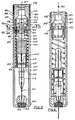
- FIG. 1 shows an injection device according to the invention with a filled syringe in a longitudinal section,
- FIG. 2 shows the same device after the lock has been released.
- FIG. 3
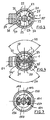
shows section 111 from FIG. 1, - FIG. 4 shows section IV from FIG. 1,
- FIG. 5 shows a second exemplary embodiment of an injection device with a filled syringe in a longitudinal section,
- Figure 6 shows the device of Figure 5 after the lock has been released, and
- 7 shows section VII from FIG. 5.
In Figur 1 bis 4 ist mit 1 ein kreiszylinderförmiges Gehäuse bezeichnet, das am vorderen Ende durch einen Deckel 2 und am hinteren Ende durch einen als Handhabe 3 dienenden Deckel verschlossen ist. Beide Deckel sind je durch eine Rast gesichert und können unter Überwindung der Rast abgenommen werden. Die Rast 57 gehört zu dem Deckel 2, ein Wulst 47 am Gehäuse und eine Einschnürung 48 an der Handhabe 3 bilden die Rast für den hinteren Deckel. Koaxial zur Achse 4 ist innerhalb des Gehäuses 1 eine Injektionsspritze 5 angeordnet. Diese Injektionsspritze 5 besteht aus einem Spritzenkörper 6, der einen kreiszylindrischen, koaxialen Flüssigkeitstank 7 aufweist. Der Flüssigkeitstank 7 ist nach vorn, das ist in Figur 1 und 2 unten, offen. Die betreffende Öffnung 8 ist kreisrund. Hinten ist der Flüssigkeitstank 7 durch einen Boden 9 geschlossen. In dem Flüssigkeitstank 7 steckt, passend von vorn eingesteckt, ein kreiszylindrischer Kolben 10, der an seinem vorderen Ende einen Nadelhalter 11 aufweist, auf den eine rückwärtige Aufsetzkappe 12 einer Injektionskanüle 13 aufgesteckt ist. Der Kolben 10 weist einen zur Achse 4 koaxialen Kanal 14 auf, der vom Inneren des Flüssigkeitstanks 7 zur Injektionskanüle führt und mit zwei Abdichtwulsten 43,44 abgedichtet ist.In Figures 1 to 4, 1 denotes a circular cylindrical housing which is closed at the front end by a
Die Injektionskanüle 13 steckt mit ihrer abgeschrägten Spitze 16 in einem Pfropfen 17 aus Dichtmaterial. Der Pfropfen 17 verschließt die vordere Öffnung 18 der Injektionskanüle. Der Pfropfen 17 verschließt außerdem einen zentralen Durchbruch 19, der in dem Deckel 2 vorgesehen ist. Das Material, aus dem der Pfropfen besteht, ist hinreichend abdichtend aber so weich, daß es von der nach vorn ausfahrenden Injektionskanüle durchstoßen werden kann.The
Am Boden 9 ist koaxial zur Achse 4 ein Bolzen 20 angeformt, der eine Ringnut 21 aufweist. Dieser Bolzen ist geführt in einem zentralen Durchbruch 23 einer gehäusefest angeordneten Stütze 22.On the
Mit 24 ist eine Manschette bezeichnet, die eine Bodenplatte 25 aufweist mit einem zentralen Durchbruch 26, durch den der Bolzen 20 gesteckt ist. Auf der Stirnseite 27 der Bodenplatte 25 stützt sich eine in Bereitstellung zusammengedrückte Schraubenfeder 28 ab, die koaxial zur Achse 4 den Spritzen körper 6 umgibt und sich vorn an einem Kragen 29 des Spritzenkörpers 6 abstützt. Der Kragen 29 bildet mit der inneren Wand des Gehäuses 1 eine Führung für die Längsbewegung des Spritzenkörpers 6 in Richtung der Achse 4.With 24 a sleeve is designated, which has a
Unter der Druckwirkung der Feder 28 stützt sich die Bodenplatte 25 der Manschette 24 an der Stütze 22 ab. Die Manschette 24 weist zwei einander diametral gegenüberstehende Flügel 32, 33 auf und paßt mit ihrer Bodenplatte 25 und diesen Flügeln gleitfähig in Richtung der Achse 4 in das Gehäuse 1. Auf der Innenseite der beiden Flügel 32, 33 ist je ein Paßkanal 34, 35 eingelassen. Die Paßkanäle stehen einander diametral gegenüber und erstrecken sich parallel zur Achse 4.Under the pressure of the
Mit 36, 37 sind zwei gleichgroße Sperrkugeln bezeichnet, die in die Ringnut 21 ragen mit etwa 1/4 ihres Durchmessers.With 36, 37 two equal-sized locking balls are designated, which protrude into the
Nach unten stützen sich die Sperrkugeln auf der Stütze 22 ab und quer dazu nach außen auf den Flügeln 32, 33. Zwischen den Flügeln 32, 33 erstrecken sich zwei Schlitze 49, 50 der Manschette 24, die bis an das rückwärtige Ende der Manschette reichen und dort offen sind. Durch diese Schlitze ragt die Stütze 22 wie aus Figur 2 ersichtlich bis an das Gehäuse 1 und ist dort verankert.Down the locking balls are supported on the
Die Sperrkugeln ragen in die Paßkanäle 34, 35, die sich vom oberen Ende der Manschette 24 bis auf die Höhe der in Sperrstellung gemäß Figur 1 befindlichen Sperrkugeln 36, 37 erstrecken. Die Sperrkugeln hindern, solange sie in die Ringnut 21 ragen, den Bolzen 20 der Federkraft der gespannten Feder 28 folgend nach vorn auszuweichen. Sie halten die Spritze 5 vielmehr sicher in der in Figur 1 gezeichneten Sperrstellung und bilden mit der Manschette 24 und dem Bolzen 20 eine allgemein mit 30 bezeichnete Sperre.The locking balls protrude into the
Die als Deckel ausgebildete Handhabe 3 ragt oben aus dem Gehäuse 1 heraus und steckt in Achsrichtung 4 verschieblich im Gehäuse 1. Die Handhabe 3 ist durch nach innen vorspringende Anschläge 47, 63 des Gehäuses und entsprechende Vorsprünge 48, 65 an der Handhabe daran gehindert, nach hinten auszuweichen. Sie sitzt in der in Figur 1 gezeichneten Sperrstellung mit ihrem vorderen Rand auf dem rückwärtigen Rand der Flügel 32, 33 der Manschette 24.The handle 3 designed as a cover protrudes from the top of the
Die rückwärtigen Enden der Paßkanäle 34, 35 sind Erweiterungen 54, 55. Am gegenüberliegenden vorwärtigen Ende der Handhabe 3 ist eine entsprechende Erweiterung 56 vorgesehen. Die Erweiterungen 54, 55 bieten bei nach vorn geschobener Handhabe 3 Platz für die Sperrkugeln, so daß diese aus der Ringnut 21 austreten können. Über die Handhabe 3 ist eine Schutzkappe 38 gestülpt, die mit einer Rast 39 gesichert auf das hintere Ende des Gehäuses gesteckt ist.The rear ends of the
Mit 51 ist ein Halteklipp bezeichnet, der es gestattet, das in Bereitstellung befindliche Injektionsgerät, das etwa die Größe eines groben Füllfederhalters hat, wie einen Füllfederhalter eingesteckt in einer Jackentasche vor dem Verlieren zu sichern.With 51 a retaining clip is designated, which allows the injection device in preparation, which is about the size of a coarse fountain pen, to be inserted into a jacket pocket and secured against loss, like a fountain pen.
In Bereitstellung ist der Flüssigkeitstank 7 und der Kanal 14 sowie das Innere der Injektionskanüle 13 mit Injektionsflüssigkeit 40 gefüllt. Wenn eine Injektion verabfolgt werden soll, wird die Schutzkappe 38 abgezogen und das Gehäuse 1 mit der vorderen Stirnfläche 46 des vorderen Deckels 2 auf die Haut aufgesetzt - im Notfall unter Zwischenlage der Garderobeund dann wird die Handhabe 3 in Pfeilrichtung 42 nach vorn gedrückt. Dadurch wird die Manschette 24 gegen die Kraftwirkung der Feder 28 ein Stück nach unten geschoben in die in Figur 2 gezeichnete Stellung, in der die Sperrkugeln 36, 37 nach außen aus der Ringnut 21 ausweichen können in die ringförmigen Erweiterungen 54, 55. Sobald die Sperrkugeln die Ringnut 21 verlassen haben, wird die Spritze 5 nicht mehr gehalten und durch die Feder 28 nach vorn getrieben. Dabei durchstößt zunächst die Injektionskanüle 13 den Pfropfen 17 und tritt an dem Durchbruch 19 aus und dringt durch die Haut in das Muskelfleisch ein, bis die Aufsetzkappe 12 in einer Konusöffnung 45 des Deckels 2 am Deckel 2 anschlägt. Der Kolben 10 kann nun nicht mehr weiter nach vorn ausweichen. Da aber der Spritzenkörper 6 noch weiter nach vorn getrieben wird, wird nun die Flüssigkeit 40 durch die Injektionskanüle 13 unter der Kraftwirkung der Feder 28 ausgetrieben und in das Muskelfleisch gespritzt, bis der Spritzenkörper am Kolben 10 anschlägt in seiner in Figure 2 gezeichnetenIn preparation, the liquid tank 7 and the
Wenn das Injektionsgerät nach durchgeführter Injektion erneut verwendet werden soll, wird zum Verankern des Bolzens 20 in der Sperre 30 die Spritze 5 unter gleichzeitigem Spannen der Feder 28 nach hinten gedrückt, und zwar über die Bereitstellung hinaus. In dieser Stellung können die Sperrkugeln 36, 37 von oben in ihre Sperrstellung einlaufen, während das Injektionsgerät mit dem hinteren Ende nach oben gehalten wird.If the injection device is to be used again after the injection has been carried out, in order to anchor the
Wenn man nun die Spritze 5 losläßt, weicht sie unter der Kraftwirkung der Feder 28 in die in Figur 1 gezeichnete Sperrstellung. In entsprechender Weise wird das Gerät auch bei der Erstmontage zusammengesetzt. Gegebenenfalls kann dabei die Handhabe 3 abgenommen werden, um die Sperrkugeln sicher in die Paßkanäle 34, 35 einzuführen. Man kann nun die geleerte und gesäuberte Injektionsspritze 5 bei herausgezogenem Kolben 10 desinfizieren. Dann wird das Innere 15 des Flüssigkeitstanks mit Injektionsflüssigkeit 40 gefüllt und der Kolben 10 eingesteckt, wobei gleichzeitig das Gerät mit dem vorderen Ende nach oben gehalten wird, so daß eine luftblasenfreie Füllung einschließlich der Injektionskanüle gesichert ist. Dann wird der Deckel 2 aufgesetzt und der Pfropfen 17 eingespritzt. Das Injektionsgerät ist nun wieder in Bereitstellung.If you let go of the syringe 5, it gives way under the force of the
Das Ausführungsbeispiel nach Figur 5 bis 7 ist dem Ausführungsbeispiel nach Figur 1 bis 4 sehr ähnlich. Es werden nachfolgend vorwiegend nur die Unterschiede beschrieben und soweit nicht beschrieben ist das Ausführungsbeispiel nach Figur 5 bis 7 genauso ausgebildet wie das Ausführungsbeispiel nach Figur 1 bis 4 und wird auch genauso betrieben.The exemplary embodiment according to FIGS. 5 to 7 is very similar to the exemplary embodiment according to FIGS. 1 to 4. Only the differences are mainly described below and, if not described, the exemplary embodiment according to FIGS. 5 to 7 is designed in exactly the same way as the exemplary embodiment according to FIGS. 1 to 4 and is also operated in the same way.
Nach Figur 5 bis 7 ist mit 101 das rohrförmige Gehäuse bezeichnet, das vorn durch einen angeformten Deckel 102 verschlossen ist und hinten durch einen als Handhabe 103 dienenden Deckel verschlossen werden kann. Mit 105 ist eine Injektionsspritze bezeichnet, deren Spritzenkörper mit 106, deren Flüssigkeitstank mit 107, deren Kolben mit 110, deren Nadelhalter mit 111, deren Aufsetzkappe mit 112 und deren Injektionsnadel mit 113 bezeichnet ist. Der Kolben 110 greift zur Abdichtung mit einem Wulst 172 in eine Ringnut 173 des Spritzenkörpers 106. Der Kolben weist vorn eine Ausnehmung 175 auf, die den Nadelhalter 111 umgibt, um den Nadelhalter zu verfedern und den Kolben vom Gewicht zu entlasten.According to FIGS. 5 to 7, 101 denotes the tubular housing, which is closed at the front by an integrally formed
Mit 129 ist ein Kragen am vorderen Ende des Spritzenkörpers 106 bezeichnet, auf dem sich eine gemäß Figur 5 zusammengedrückt gespannte Schraubenfeder 128 abstützt. Am rückwärtigen Ende des Spritzenkörpers 106 ist koaxial zur Achse 104 des Gehäuses ein Bolzen 120 befestigt, der diametral einander gegenüberliegend zwei langgestreckte Ausnehmungen 160,161 aufweist, die sich parallel zur Achse 104 erstrecken und in die zwei Sperrkugeln 136, 137 passen. Mit 124 ist eine Manschette bezeichnet, auf deren Stirnseite 127 sich nach Figur 5 die Schraubenfeder 128 abstützt. Die Manschette 124 ihrerseits stützt sich nach hinten auf der Handhabe 103 ab, die sich ihrerseits mit zwei einander diametral gegenüberliegenden Vorsprüngen 148, 165 auf zwei diametral gegenüberliegenden, gehäusefesten Anschlägen 147, 163 nach hinten abstützt. Die Handhabe 103 kann nach Art eines Bajonett-Verschlusses gelöst werden, indem sie um 90 Grad, bezogen auf die Achse 104, im Gehäuse gedreht wird. Dann sind die Vorsprünge 148,165 frei von den Anschlägen 147, 163 und finden Platz in Kanälen des Gehäuses, die in der Zeichnung nicht sichtbar sind, so daß in der gegenüber der Zeichnung um 90 Grad verdrehten Stellung der Handhabe diese nach oben aus dem Gehäuse herausgezogen werden kann.A collar at the front end of the syringe body 106 is designated by 129, on which a helical spring 128 which is compressed according to FIG. 5 is supported. At the rear end of the syringe body 106, a
Die Manschette 124 weist diametral einander gegenüberliegend zwei Paßkanäle 134, 135 auf, in die die Sperrkugeln 136, 137 gemäß Figur 5 passen. Die Sperrkugeln stützen sich nach vorn gemäß Figur 5 auf einer Stütze 122 ab, die den Bolzen 120 umgibt und die Manschette 124 durchsetzt. Diese Stütze 122 ist ein loses Teil, das nach vorn beidseitig an einem gehäusefesten Anschlag 166, 167 abgestützt ist. Die Injektionsspritze 105 stützt sich gemäß Figur 5 gegen die Kraftwirkung der Schraubenfeder 128 über die Sperrkugeln 136, 137 und über die Stütze 122 an den Anschlägen 166,167 ab. Die Sperrkugeln 136, 137 können nicht ausweichen, da sie nach Figur 5 formschlüssig in die Ausnehmungen 160, 161 und die Paßkanäle 134, 135 passen. Die so gebildete Sperre ist allgemein mit 130 bezeichnet. Die Stütze 122 durchsetzt die Manschette in zwei Schlitzen 149, 150, die bis an das rückwärtige Ende der Manschette reichen.The
Mit 138 ist eine lose aufgesetzte, abziehbare Schutzkappe bezeichnet, die sich aufgesetzt auf dem Gehäuse 101 abstützt und stabil genug ist, um als Sicherung gegen unbeabsichtigtes Niederdrücken der Handhabe 103 zu dienen. Mit 117 ist ein von der Injektionsnadel 113 durchstoßbarer Pfropfen bezeichnet, der einen Durchbruch 119 im Deckel 102 gemäß Figur 5 verschließt. Mit 154, 155 sind zwei Erweiterungen am rückwärtigen Ende der Paßkanäle 134,135 bezeichnet, in denen die Sperrkugeln 136, 137 genügend Platz finden, um die Injektionsspritze 105 freizugeben.138 with a loosely placed, removable protective cap is referred to, which is supported on the
Zur Auslösung des Spritzvorganges wird die Schutzkappe 138 entfernt und die Handhabe 103 in Pfeilrichtung 142 gegen die Kraftwirkung der gespannten Schraubenfeder 128 nach vorn gedrückt. Dadurch verschiebt sich die Manschette 124 nach vorn. Die Sperre 130 bleibt stehen und findet Platz in den Schlitzen 149, 150 der Manschette 124. Diese Schlitze erstrecken sich parallel zur Achse 104. Beim Vorschub der Manschette 124 geraten die Sperrkugeln schließlich in den Bereich der Erweiterungen 154, 155 und können nach außen ausweichen und geben dadurch den Bolzen 120 frei. Die Injektionsspritze 105 wird nun durch die Feder 128 nach vorn getrieben bis die Aufsetzkappe 112 auf dem Deckel 102 anschlägt. Die Injektionsnadel 113 hat bis dahin den Pfropfen 117 durchsetzt, wie aus Figur 6 ersichtlich. Die Schraubenfeder 128 treibt nun den Spritzenkörper 106 weiter nach vorn, nachdem sie die Rastwirkung des Wulstes 172 in der Ringnut 173 überwunden hat, bis der Kolben 110 auf dem Boden 109 anschlägt, wobei die Injektionsflüssigkeit aus dem Flüssigkeitstank 107 ausgetrieben wird.To trigger the spraying process, the
Zum Wiederbefüllen wird die Handhabe 103 durch Verdrehen um 90 Grad gelöst und nach hinten abgezogen. Ist das geschehen, dann können sämtliche Teile, die sich innerhalb des Gehäuses 101 befinden, nach hintenFor refilling, the
herausgezogen werden. Die Injektionsspritze 105 wird dann gefüllt, es wird ein neuer Pfropfen 117 eingesetzt und die Teile werden von hinten wieder eingeführt, und zwar zunächst die gefüllte Injektionsspritze 105 mit der Manschette 124, der in die Manschette eingesteckten Sperre 130 mit in Sperrstellung befindlichen Sperrkugeln 136, 137 und der dazwischen vorgespannten Schraubenfeder 128. Dann wird die Handhabe 103 aufgesetzt und dabei die Schraubenfeder 128 etwas nachgespannt und dann wird die Handhabe 103 durch Verdrehen um 90 Grad an den Anschlägen 147, 163 gesichert und die Schutzkappe 138 wird aufgesetzt. In entsprechender Weise erfolgt auch die Montage.be pulled out. The
Claims (11)
Priority Applications (1)
| Application Number | Priority Date | Filing Date | Title |
|---|---|---|---|
| AT84112180T ATE36243T1 (en) | 1983-11-24 | 1984-10-11 | INJECTION DEVICE. |
Applications Claiming Priority (2)
| Application Number | Priority Date | Filing Date | Title |
|---|---|---|---|
| DE3342407 | 1983-11-24 | ||
| DE19833342407 DE3342407A1 (en) | 1983-11-24 | 1983-11-24 | INJECTION DEVICE |
Publications (3)
| Publication Number | Publication Date |
|---|---|
| EP0144625A2 EP0144625A2 (en) | 1985-06-19 |
| EP0144625A3 EP0144625A3 (en) | 1986-10-29 |
| EP0144625B1 true EP0144625B1 (en) | 1988-08-10 |
Family
ID=6215093
Family Applications (1)
| Application Number | Title | Priority Date | Filing Date |
|---|---|---|---|
| EP84112180A Expired EP0144625B1 (en) | 1983-11-24 | 1984-10-11 | Injection device |
Country Status (3)
| Country | Link |
|---|---|
| EP (1) | EP0144625B1 (en) |
| AT (1) | ATE36243T1 (en) |
| DE (2) | DE3342407A1 (en) |
Cited By (4)
| Publication number | Priority date | Publication date | Assignee | Title |
|---|---|---|---|---|
| WO1988000066A1 (en) * | 1986-07-01 | 1988-01-14 | Schlueter Eberhardt | Automatic injection device, and ampoule or cartridge for an injection device |
| EP0457135A2 (en) * | 1990-05-12 | 1991-11-21 | Klaus Nothdurft | Control device for single-use syringe |
| WO1999056805A1 (en) | 1998-04-30 | 1999-11-11 | Schering Aktiengesellschaft | Injection device |
| WO2017053261A1 (en) * | 2015-09-24 | 2017-03-30 | Vidacare LLC | Infusing devices, systems, and methods |
Families Citing this family (35)
| Publication number | Priority date | Publication date | Assignee | Title |
|---|---|---|---|---|
| US5085641A (en) * | 1989-07-17 | 1992-02-04 | Survival Technology, Inc. | Conveniently carried frequent use auto-injector with improved cap structure |
| GB9118204D0 (en) * | 1991-08-23 | 1991-10-09 | Weston Terence E | Needle-less injector |
| DE19532410C2 (en) * | 1995-09-01 | 1998-02-05 | Gaplast Gmbh | Injection device |
| DE19824016C1 (en) * | 1998-05-29 | 2000-02-03 | Fresenius Ag | Implantable device for applying an active solution |
| US7252651B2 (en) | 2003-01-07 | 2007-08-07 | Becton, Dickinson And Company | Disposable injection device |
| GB2414403B (en) | 2004-05-28 | 2009-01-07 | Cilag Ag Int | Injection device |
| GB2414775B (en) | 2004-05-28 | 2008-05-21 | Cilag Ag Int | Releasable coupling and injection device |
| GB2414399B (en) | 2004-05-28 | 2008-12-31 | Cilag Ag Int | Injection device |
| GB2414402B (en) | 2004-05-28 | 2009-04-22 | Cilag Ag Int | Injection device |
| GB2414409B (en) | 2004-05-28 | 2009-11-18 | Cilag Ag Int | Injection device |
| GB2414406B (en) | 2004-05-28 | 2009-03-18 | Cilag Ag Int | Injection device |
| GB2414400B (en) | 2004-05-28 | 2009-01-14 | Cilag Ag Int | Injection device |
| GB2414401B (en) | 2004-05-28 | 2009-06-17 | Cilag Ag Int | Injection device |
| GB2414405B (en) * | 2004-05-28 | 2009-01-14 | Cilag Ag Int | Injection device |
| GB2424836B (en) | 2005-04-06 | 2010-09-22 | Cilag Ag Int | Injection device (bayonet cap removal) |
| GB2424838B (en) | 2005-04-06 | 2011-02-23 | Cilag Ag Int | Injection device (adaptable drive) |
| GB2424835B (en) | 2005-04-06 | 2010-06-09 | Cilag Ag Int | Injection device (modified trigger) |
| GB2425062B (en) | 2005-04-06 | 2010-07-21 | Cilag Ag Int | Injection device |
| GB2427826B (en) | 2005-04-06 | 2010-08-25 | Cilag Ag Int | Injection device comprising a locking mechanism associated with integrally formed biasing means |
| EP1759729B1 (en) | 2005-08-30 | 2009-12-23 | Cilag GmbH International | Needle assembly for a prefilled syringe system |
| US20110098656A1 (en) | 2005-09-27 | 2011-04-28 | Burnell Rosie L | Auto-injection device with needle protecting cap having outer and inner sleeves |
| GB2438590B (en) | 2006-06-01 | 2011-02-09 | Cilag Gmbh Int | Injection device |
| GB2438593B (en) | 2006-06-01 | 2011-03-30 | Cilag Gmbh Int | Injection device (cap removal feature) |
| GB2438591B (en) | 2006-06-01 | 2011-07-13 | Cilag Gmbh Int | Injection device |
| DE102007008369A1 (en) * | 2007-02-16 | 2008-08-21 | Lts Lohmann Therapie-Systeme Ag | Disposable injector with at least one central tie rod |
| GB2461086B (en) | 2008-06-19 | 2012-12-05 | Cilag Gmbh Int | Injection device |
| GB2461087B (en) | 2008-06-19 | 2012-09-26 | Cilag Gmbh Int | Injection device |
| GB2461089B (en) | 2008-06-19 | 2012-09-19 | Cilag Gmbh Int | Injection device |
| GB2461085B (en) | 2008-06-19 | 2012-08-29 | Cilag Gmbh Int | Injection device |
| GB2461084B (en) | 2008-06-19 | 2012-09-26 | Cilag Gmbh Int | Fluid transfer assembly |
| GB2515039B (en) | 2013-06-11 | 2015-05-27 | Cilag Gmbh Int | Injection Device |
| GB2515032A (en) | 2013-06-11 | 2014-12-17 | Cilag Gmbh Int | Guide for an injection device |
| GB2515038A (en) | 2013-06-11 | 2014-12-17 | Cilag Gmbh Int | Injection device |
| GB2517896B (en) | 2013-06-11 | 2015-07-08 | Cilag Gmbh Int | Injection device |
| IL268042B2 (en) * | 2017-01-17 | 2023-04-01 | Becton Dickinson & Co Ltd | Syringe adapter for closed transfer of fluids |
Family Cites Families (2)
| Publication number | Priority date | Publication date | Assignee | Title |
|---|---|---|---|---|
| US3543603A (en) * | 1968-01-10 | 1970-12-01 | Rex Chainbelt Inc | Automatic quick release mechanism |
| NO124977B (en) * | 1968-08-09 | 1972-07-03 | Philips Nv |
-
1983
- 1983-11-24 DE DE19833342407 patent/DE3342407A1/en not_active Withdrawn
-
1984
- 1984-10-11 EP EP84112180A patent/EP0144625B1/en not_active Expired
- 1984-10-11 AT AT84112180T patent/ATE36243T1/en not_active IP Right Cessation
- 1984-10-11 DE DE8484112180T patent/DE3473230D1/en not_active Expired
Cited By (6)
| Publication number | Priority date | Publication date | Assignee | Title |
|---|---|---|---|---|
| WO1988000066A1 (en) * | 1986-07-01 | 1988-01-14 | Schlueter Eberhardt | Automatic injection device, and ampoule or cartridge for an injection device |
| EP0261318A1 (en) * | 1986-07-01 | 1988-03-30 | Eberhardt Dipl.-Kfm. Schlüter | Automatic injection device and cartridge with needle therefor |
| EP0457135A2 (en) * | 1990-05-12 | 1991-11-21 | Klaus Nothdurft | Control device for single-use syringe |
| EP0457135A3 (en) * | 1990-05-12 | 1992-01-15 | Klaus Nothdurft | Control device for single-use syringe |
| WO1999056805A1 (en) | 1998-04-30 | 1999-11-11 | Schering Aktiengesellschaft | Injection device |
| WO2017053261A1 (en) * | 2015-09-24 | 2017-03-30 | Vidacare LLC | Infusing devices, systems, and methods |
Also Published As
| Publication number | Publication date |
|---|---|
| EP0144625A3 (en) | 1986-10-29 |
| DE3473230D1 (en) | 1988-09-15 |
| DE3342407A1 (en) | 1985-06-05 |
| EP0144625A2 (en) | 1985-06-19 |
| ATE36243T1 (en) | 1988-08-15 |
Similar Documents
| Publication | Publication Date | Title |
|---|---|---|
| EP0144625B1 (en) | Injection device | |
| DE902776C (en) | Automatic injection device with ampoule | |
| DE60013565T2 (en) | DEVICE FOR BIDIRECTIONALLY TRANSFERRING LIQUID IN A FLACON TO AN AMPOULE | |
| DE4037418C2 (en) | Liquid medication delivery device | |
| DE69724784T2 (en) | DEVICE FOR AUTOMATICALLY INSERTING A NEEDLE | |
| DE102004042581B4 (en) | Auto-Pen for dual-chamber ampoule | |
| DE60218296T2 (en) | KIT WITH A SYRINGE PAD WITH SIDE OPENING FOR PREPARING A MEDICAMENT IN AN INJECTION PEN CARTRIDGE | |
| DE69724291T2 (en) | SYRINGE WITH RETRACTABLE NEEDLE DEVICE | |
| DE2436000C2 (en) | Automatic injection syringe | |
| EP1198263B1 (en) | Device for automatically injecting injection liquids | |
| DE602005003009T2 (en) | INJECTION DEVICE | |
| DE69433366T2 (en) | Needle-free injector | |
| DE3823266C2 (en) | Spray ampoule | |
| DE2431347A1 (en) | SELF-INJECTION SYRINGE | |
| DD245817A5 (en) | AUTOMATIC INJECTION DEVICE | |
| AT398037B (en) | DEVICE FOR SELF-INJECTION | |
| CH661445A5 (en) | NEEDLE-FREE HYPODERMATIC INJECTOR. | |
| DE1094932B (en) | Injection device | |
| WO1998011927A1 (en) | Expulsion member for advancing the stopper of a syringe ampoule and a corresponding stopper | |
| DE3346856A1 (en) | INJECTION DEVICE | |
| DE2305842A1 (en) | INJECTION DEVICE | |
| CH400462A (en) | Injection syringe | |
| DE1287743B (en) | ||
| DE19821934C1 (en) | Device for the dosed administration of an injectable product | |
| DE60013888T2 (en) | DISPOSABLE INSPECTION INTENDED FOR INJECTIONS AND LABORATORY TESTS |
Legal Events
| Date | Code | Title | Description |
|---|---|---|---|
| PUAI | Public reference made under article 153(3) epc to a published international application that has entered the european phase |
Free format text: ORIGINAL CODE: 0009012 |
|
| AK | Designated contracting states |
Designated state(s): AT BE CH DE FR GB IT LI LU NL SE |
|
| PUAL | Search report despatched |
Free format text: ORIGINAL CODE: 0009013 |
|
| AK | Designated contracting states |
Kind code of ref document: A3 Designated state(s): AT BE CH DE FR GB IT LI LU NL SE |
|
| 17P | Request for examination filed |
Effective date: 19861107 |
|
| 17Q | First examination report despatched |
Effective date: 19880105 |
|
| GRAA | (expected) grant |
Free format text: ORIGINAL CODE: 0009210 |
|
| AK | Designated contracting states |
Kind code of ref document: B1 Designated state(s): AT BE CH DE FR GB IT LI LU NL SE |
|
| PG25 | Lapsed in a contracting state [announced via postgrant information from national office to epo] |
Ref country code: SE Effective date: 19880810 Ref country code: NL Effective date: 19880810 Ref country code: IT Free format text: LAPSE BECAUSE OF FAILURE TO SUBMIT A TRANSLATION OF THE DESCRIPTION OR TO PAY THE FEE WITHIN THE PRESCRIBED TIME-LIMIT;WARNING: LAPSES OF ITALIAN PATENTS WITH EFFECTIVE DATE BEFORE 2007 MAY HAVE OCCURRED AT ANY TIME BEFORE 2007. THE CORRECT EFFECTIVE DATE MAY BE DIFFERENT FROM THE ONE RECORDED. Effective date: 19880810 |
|
| REF | Corresponds to: |
Ref document number: 36243 Country of ref document: AT Date of ref document: 19880815 Kind code of ref document: T |
|
| REF | Corresponds to: |
Ref document number: 3473230 Country of ref document: DE Date of ref document: 19880915 |
|
| ET | Fr: translation filed | ||
| PG25 | Lapsed in a contracting state [announced via postgrant information from national office to epo] |
Ref country code: LU Free format text: LAPSE BECAUSE OF NON-PAYMENT OF DUE FEES Effective date: 19881031 |
|
| GBT | Gb: translation of ep patent filed (gb section 77(6)(a)/1977) | ||
| NLV1 | Nl: lapsed or annulled due to failure to fulfill the requirements of art. 29p and 29m of the patents act | ||
| PLBE | No opposition filed within time limit |
Free format text: ORIGINAL CODE: 0009261 |
|
| STAA | Information on the status of an ep patent application or granted ep patent |
Free format text: STATUS: NO OPPOSITION FILED WITHIN TIME LIMIT |
|
| 26N | No opposition filed | ||
| PGFP | Annual fee paid to national office [announced via postgrant information from national office to epo] |
Ref country code: CH Payment date: 19890929 Year of fee payment: 6 |
|
| PGFP | Annual fee paid to national office [announced via postgrant information from national office to epo] |
Ref country code: FR Payment date: 19891004 Year of fee payment: 6 Ref country code: AT Payment date: 19891004 Year of fee payment: 6 |
|
| PGFP | Annual fee paid to national office [announced via postgrant information from national office to epo] |
Ref country code: BE Payment date: 19891009 Year of fee payment: 6 |
|
| PGFP | Annual fee paid to national office [announced via postgrant information from national office to epo] |
Ref country code: GB Payment date: 19891031 Year of fee payment: 6 |
|
| PG25 | Lapsed in a contracting state [announced via postgrant information from national office to epo] |
Ref country code: GB Effective date: 19901011 Ref country code: AT Effective date: 19901011 |
|
| PG25 | Lapsed in a contracting state [announced via postgrant information from national office to epo] |
Ref country code: LI Effective date: 19901031 Ref country code: CH Effective date: 19901031 Ref country code: BE Effective date: 19901031 |
|
| BERE | Be: lapsed |
Owner name: MAURER ERWIN Effective date: 19901031 |
|
| GBPC | Gb: european patent ceased through non-payment of renewal fee | ||
| PG25 | Lapsed in a contracting state [announced via postgrant information from national office to epo] |
Ref country code: FR Effective date: 19910628 |
|
| REG | Reference to a national code |
Ref country code: CH Ref legal event code: PL |
|
| REG | Reference to a national code |
Ref country code: FR Ref legal event code: ST |
|
| PGFP | Annual fee paid to national office [announced via postgrant information from national office to epo] |
Ref country code: DE Payment date: 19921216 Year of fee payment: 9 |
|
| PG25 | Lapsed in a contracting state [announced via postgrant information from national office to epo] |
Ref country code: DE Effective date: 19940701 |