EP0144584A2 - Holder for injecting a bonding agent into a bore-hole for the anchoring of a fixing device - Google Patents
Holder for injecting a bonding agent into a bore-hole for the anchoring of a fixing device Download PDFInfo
- Publication number
- EP0144584A2 EP0144584A2 EP84111534A EP84111534A EP0144584A2 EP 0144584 A2 EP0144584 A2 EP 0144584A2 EP 84111534 A EP84111534 A EP 84111534A EP 84111534 A EP84111534 A EP 84111534A EP 0144584 A2 EP0144584 A2 EP 0144584A2
- Authority
- EP
- European Patent Office
- Prior art keywords
- piston
- spray nozzle
- container
- container housing
- binder
- Prior art date
- Legal status (The legal status is an assumption and is not a legal conclusion. Google has not performed a legal analysis and makes no representation as to the accuracy of the status listed.)
- Granted
Links
Images
Classifications
-
- B—PERFORMING OPERATIONS; TRANSPORTING
- B65—CONVEYING; PACKING; STORING; HANDLING THIN OR FILAMENTARY MATERIAL
- B65D—CONTAINERS FOR STORAGE OR TRANSPORT OF ARTICLES OR MATERIALS, e.g. BAGS, BARRELS, BOTTLES, BOXES, CANS, CARTONS, CRATES, DRUMS, JARS, TANKS, HOPPERS, FORWARDING CONTAINERS; ACCESSORIES, CLOSURES, OR FITTINGS THEREFOR; PACKAGING ELEMENTS; PACKAGES
- B65D83/00—Containers or packages with special means for dispensing contents
- B65D83/76—Containers or packages with special means for dispensing contents for dispensing fluent contents by means of a piston
- B65D83/767—Containers or packages with special means for dispensing contents for dispensing fluent contents by means of a piston the piston having an integrated dispensing opening
-
- B—PERFORMING OPERATIONS; TRANSPORTING
- B05—SPRAYING OR ATOMISING IN GENERAL; APPLYING FLUENT MATERIALS TO SURFACES, IN GENERAL
- B05C—APPARATUS FOR APPLYING FLUENT MATERIALS TO SURFACES, IN GENERAL
- B05C21/00—Accessories or implements for use in connection with applying liquids or other fluent materials to surfaces, not provided for in groups B05C1/00 - B05C19/00
-
- B—PERFORMING OPERATIONS; TRANSPORTING
- B05—SPRAYING OR ATOMISING IN GENERAL; APPLYING FLUENT MATERIALS TO SURFACES, IN GENERAL
- B05C—APPARATUS FOR APPLYING FLUENT MATERIALS TO SURFACES, IN GENERAL
- B05C7/00—Apparatus specially designed for applying liquid or other fluent material to the inside of hollow work
- B05C7/02—Apparatus specially designed for applying liquid or other fluent material to the inside of hollow work the liquid or other fluent material being projected
-
- F—MECHANICAL ENGINEERING; LIGHTING; HEATING; WEAPONS; BLASTING
- F16—ENGINEERING ELEMENTS AND UNITS; GENERAL MEASURES FOR PRODUCING AND MAINTAINING EFFECTIVE FUNCTIONING OF MACHINES OR INSTALLATIONS; THERMAL INSULATION IN GENERAL
- F16B—DEVICES FOR FASTENING OR SECURING CONSTRUCTIONAL ELEMENTS OR MACHINE PARTS TOGETHER, e.g. NAILS, BOLTS, CIRCLIPS, CLAMPS, CLIPS OR WEDGES; JOINTS OR JOINTING
- F16B13/00—Dowels or other devices fastened in walls or the like by inserting them in holes made therein for that purpose
- F16B13/14—Non-metallic plugs or sleeves; Use of liquid, loose solid or kneadable material therefor
- F16B13/141—Fixing plugs in holes by the use of settable material
Definitions
- the invention relates to a container for spraying out a binder for anchoring a fastening element in a borehole, consisting of the container housing containing and sealing a component of the binder, a spray nozzle and a piston which is displaceable in the container housing.
- the holding force of conventional fastening elements is based on the wedging of an expandable part of the fastening element in the borehole, for example by screwing in a fastening screw.
- the spreading creates tensions which, particularly in porous and soft masonry materials, allow only low holding forces.
- Fastening elements which can be anchored stress-free by extrusion coating with a binder, have proven particularly useful for such materials.
- the binder for example a cement mixture
- the binder for example a cement mixture
- spraying device for example a cement mixture
- Another container is required to mix the binder. Both the spraying device and this additional vessel must be cleaned immediately after use or at short, regular intervals during series assembly in order to prevent the equipment from freezing and becoming unusable.
- the invention is therefore based on the object of creating a disposable container which can be produced inexpensively and with which the binder mixed in the container can be sprayed out without additional aids.
- this is achieved in that the spray nozzle is arranged on the piston and the total length of the piston and spray nozzle corresponds to the interior height of the container housing.
- the cylindrical container housing which consists, for example, of an impregnated cardboard or sheet metal, contains the amount of one component of the binder which is required for assembly.
- the bottom of the container housing is firmly connected to the casing, while after the one component has been filled in, the opening is closed with an airtight cover and / or a tear film.
- the lid or tear film is removed and the second component - in the case of a cement mixture - is filled with water.
- the piston provided with the spray nozzle is placed on the opening and the nozzle is placed on the injection opening on the fastening element. Pressure on the bottom of the container housing causes the plunger to penetrate the container, pushing the mixture through the spray nozzle into the borehole. Since the total length of the piston with the spray nozzle corresponds to the interior height of the container housing, the mixture can be sprayed out completely.
- the piston can have a cup-shaped depression which is open in the direction of the spray nozzle and whose filling volume for the other component corresponds to the Mi ratio or an integer part of the mixing ratio with respect to the filling quantity of the component contained in the container housing.
- the piston can be used as a measuring cup for filling the other component. Since one or more whole fillings each correspond to the correct mixing ratio, it is ensured that the optimum properties of the binder are always present. This also makes it easier for an inexperienced person to carry out the anchoring process.
- the container housing 1 consisting of an impregnated cardboard or sheet metal is designed as a cup-shaped hollow cylinder with a bottom 2. After the one component 3 has been filled into the container housing 1, the latter is blown through a tear film 4 and / or optionally through a plastic cover 5. Also part of the container is a cup-shaped piston 6, the bottom 7 of which has the spray nozzle 9 projecting beyond the edge 8 of the piston 6. To stabilize the injection nozzle 9, which is produced in one piece with the piston 6 by injection molding, ribs 10 connected to the base 7 of the piston 6 are provided.
- the filling volume of the cup-shaped recess 11 of the piston 6 is designed so that one or more whole fillings of the other component - at In a cement mixture, this component is water - corresponds to the optimal mixing ratio.
- the spray nozzle 9 is attached to the filling opening 12 of the fastening element 13, and the cement mixture is pressed through the spray nozzle 9 and the sleeve 14 inserted into the fastening element 13 by pressure on the bottom 2 of the container housing 1 the hole 15 injected.
- the container housing 1 is moved in the direction of the masonry surface, while the piston 6 with the spray nozzle 9 is supported on the fastening element 13. Since the total height of the piston and the spray nozzle corresponds to the interior height of the container housing, the cement mixture can be completely sprayed out.
- the bottom of the piston can have an inlet funnel 16.
Landscapes
- Engineering & Computer Science (AREA)
- General Engineering & Computer Science (AREA)
- Mechanical Engineering (AREA)
- Piles And Underground Anchors (AREA)
- Joining Of Building Structures In Genera (AREA)
- Containers And Packaging Bodies Having A Special Means To Remove Contents (AREA)
- Nozzles (AREA)
- Perforating, Stamping-Out Or Severing By Means Other Than Cutting (AREA)
- Polishing Bodies And Polishing Tools (AREA)
- Details Or Accessories Of Spraying Plant Or Apparatus (AREA)
- Earth Drilling (AREA)
- Basic Packing Technique (AREA)
- Standing Axle, Rod, Or Tube Structures Coupled By Welding, Adhesion, Or Deposition (AREA)
- Coating Apparatus (AREA)
- Adhesives Or Adhesive Processes (AREA)
Abstract
Die Erfindung betrifft einen Behälter zum Ausspritzen eines Bindemittels für die Verankerung eines Befestigungselementes in einem Bohrloch. Der Behälter besteht aus dem eine Komponente des Bindemittels enthaltenden und verschließbaren Behältergehäuse, einer Spritzdüse und einem im Behältergehäuse verschiebbaren Kolben. Die Spritzdüse ist am Kolben angeordnet und die Gesamtlänge von Kolben und Spritzdüse der Innenraumhöhe des Behältergehäuses angepaßt. Dadurch kann durch Druck auf den Boden des Behältergehäuses das Bindemittel vollständig ausgespritzt werden.The invention relates to a container for spraying out a binder for anchoring a fastening element in a borehole. The container consists of the closable container housing containing a component of the binder, a spray nozzle and a piston which is displaceable in the container housing. The spray nozzle is arranged on the piston and the total length of the piston and spray nozzle is adapted to the interior height of the container housing. As a result, the binder can be completely sprayed out by pressure on the bottom of the container housing.
Description
Die.Erfindung betrifft einen Behälter zum Ausspritzen eines Bindemittels für die Verankerung eines Befestigungselementes in einem Bohrloch, bestehend aus dem eine Komponente des Bindemittels enthaltenden und verschließbaren Behältergehäuse, einer Spritzdüse und einem im Behältergehäuse verschiebbaren Kolben.The invention relates to a container for spraying out a binder for anchoring a fastening element in a borehole, consisting of the container housing containing and sealing a component of the binder, a spray nozzle and a piston which is displaceable in the container housing.
Die Haltekraft herkömmlicher Befestigungselemente beruht auf der-Verkeilung eines spreizbaren Teiles des Befestigungselementes im Bohrloch beispielsweise durch Eindrehen einer Befestigungsschraube. Durch das Aufspreizen entstehen allerdings Spannungen, die insbesondere in porösen und weichen Mauerwerksstoffen nur geringe Haltekräfte ermöglichen. Für solche Werkstoffe haben sich insbesondere Befestigungselemente bewährt, die durch Umspritzen mit einem Bindemittel spannungsfrei verankerbar sind. Bei einem bekannten Verankerungsverfahren dieser Art wird das Bindemittel, beispielsweise eine Zementmischung nach der Anmischung in eine Spritzvorrichtung aufgezogen und mit dieser dann ins Bohrloch eingespritzt. Für Einzelmontagen lohnt sich jedoch in der Regel nicht die Anschaffung einer solchen Spritzvorrichtung. Außerdem ist für die Anmischung des Bindemittels ein weiteres Gefäß erforderlich. Sowohl die Spritzvorrichtung als auch dieses weitere Gefäß sind sofort nach Gebrauch, bzw. bei Serienmontagen in kurzen, regelmäßigen Abständen zu reinigen, um das Einfrieren und damit das Unbrauchbarwerden der Geräte zu verhindern.The holding force of conventional fastening elements is based on the wedging of an expandable part of the fastening element in the borehole, for example by screwing in a fastening screw. The spreading, however, creates tensions which, particularly in porous and soft masonry materials, allow only low holding forces. Fastening elements, which can be anchored stress-free by extrusion coating with a binder, have proven particularly useful for such materials. In a known anchoring method of this type, the binder, for example a cement mixture, is drawn into a spraying device after mixing and then injected into the borehole. For individual assemblies, however, it is usually not worth buying such a spraying device. Another container is required to mix the binder. Both the spraying device and this additional vessel must be cleaned immediately after use or at short, regular intervals during series assembly in order to prevent the equipment from freezing and becoming unusable.
Au.s der DE-OS 27 30 110 ist ein Behälter fUr den Einmalgebrauch bekannt. Allerdings ist dieser Behälter in der Herstellung noch sehr kostenaufwendig. Auch die Handhabung bereitet Schwierigkeiten, da zum Eindrücken des Kolbens ein stabförmiges Hilfsmittel erforderlich ist.From DE-OS 27 30 110 a container for single use is known. However, this container is still very expensive to manufacture. Handling be is experiencing difficulties because a rod-shaped tool is required to press the piston in.
Der Erfindung liegt daher die Aufgabe zugrunde, einen kostengünstig herstellbaren.Behälter für den Einmalgebrauch zu schaffen, mit dem ohne zusätzliche Hilfsmittel ein Ausspritzen des im Behälter angerührten Bindemittels möglich ist.The invention is therefore based on the object of creating a disposable container which can be produced inexpensively and with which the binder mixed in the container can be sprayed out without additional aids.
Erfindungsgemäß wird dies dadurch erreicht, daß die Spritzdüse am Kolben angeordnet ist, und die Gesamtlänge von Kolben und Spritzdüse der Innenraumhöhe des Behältergehäuses entspricht.According to the invention, this is achieved in that the spray nozzle is arranged on the piston and the total length of the piston and spray nozzle corresponds to the interior height of the container housing.
Das beispielsweise aus einem imprägnierten Karton oder Blech bestehende zylinderförmige Behältergehäuse enthält die Menge der einen Komponente des Bindemittels, die für eine Montage erforderlich ist. Der Boden des Behältergehäuses ist fest mit dem Mantel verbunden, während die öffnung nach dem Einfüllen der einen Komponente mit einem luftdicht abschließenden Deckel und/oder einer Reißfolie verschlossen ist. Zum Anmischen des Bindemittels, im Regelfall einer Zementmischung, wird der Deckel bzw. die Reißfolie entfernt und die zweite Komponente - bei einer Zementmischung Wasser - eingefüllt. Nach dem Anrühren der Mischung wird der mit der Spritzdüse versehene Kolben auf die öffnung aufgesetzt und die Düse an die Einspritzöffnung am Befestigungselement angesetzt. Durch Druck auf den Boden des Behältergehäuses dringt der Kolben in den Behälter ein und drückt dabei die Mischung durch die Spritzdüse in das Bohrloch. Da die Gesamtlänge des Kolbens mit der Spritzdüse der Innenraumhöhe des Behältergehäuses entspricht, kann die Mischung vollständig ausgespritzt werden.The cylindrical container housing, which consists, for example, of an impregnated cardboard or sheet metal, contains the amount of one component of the binder which is required for assembly. The bottom of the container housing is firmly connected to the casing, while after the one component has been filled in, the opening is closed with an airtight cover and / or a tear film. To mix the binder, usually a cement mixture, the lid or tear film is removed and the second component - in the case of a cement mixture - is filled with water. After the mixture has been stirred, the piston provided with the spray nozzle is placed on the opening and the nozzle is placed on the injection opening on the fastening element. Pressure on the bottom of the container housing causes the plunger to penetrate the container, pushing the mixture through the spray nozzle into the borehole. Since the total length of the piston with the spray nozzle corresponds to the interior height of the container housing, the mixture can be sprayed out completely.
In einer weiteren Ausgestaltung der Erfindung kann der Kolben eine in Richtung SpritzdUse offene napfförmige Vertiefung aufweisen, deren Füllvolumen für die andere Komponente dem Mischungsverhältnis bzw. einem ganzzahligen Teil des Mischungsverhältnisses bezüglich der Füllmenge der im Behältergehäuse enthaltenen Komponente entspricht. Durch diese Gestaltung kann der Kolben als Meßbecher für das Einfüllen der anderen Komponente verwendet werden. Da ein oder mehrere ganze Füllungen jeweils dem richtigen Mischungsverhältnis entsprechen, ist dafür gesorgt, daß stets die optimalen Eigenschaften des Bindemittels vorliegen. Dies erleichtert auch für einen Ungeübten die Durchführung des Verankerungsverfahrens.In a further embodiment of the invention, the piston can have a cup-shaped depression which is open in the direction of the spray nozzle and whose filling volume for the other component corresponds to the Mi ratio or an integer part of the mixing ratio with respect to the filling quantity of the component contained in the container housing. With this design, the piston can be used as a measuring cup for filling the other component. Since one or more whole fillings each correspond to the correct mixing ratio, it is ensured that the optimum properties of the binder are always present. This also makes it easier for an inexperienced person to carry out the anchoring process.
In der Zeichnung ist eine Ausführungsbeispiel der Erfindung dargestellt.In the drawing, an embodiment of the invention is shown.
Es zeigen:
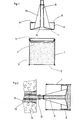
- Figur 1 das mit einer Komponente gefüllte und verschlossene Behältergehäuse mit dem die Spritzdüse aufweisenden Kolben
- Figur 2 das in einer Bohrung im Mauerwerk eingesetzte Befestigungselement nach dem Ausspritzen.
- 1 shows the container housing filled and sealed with a component with the piston having the spray nozzle
- Figure 2 shows the fastener used in a hole in the masonry after spraying.
Das aus einem imprägnierten Karton oder Blech bestehende Behältergehäuse 1 ist als napfförmiger Hohlzylinder mit Boden 2 ausgebildet. Nach dem Einfüllen der einen Komponente 3 in das Behältergehäuse 1 wird dieses durch eine Reißfolie 4 und/oder gegebenenfalls durch einen Kunststoffdeckel 5 yerscblossen. Bestandteil des Behälters ist ferner ein napfförmig ausgebildeter Kolben 6, dessen Boden 7 die über den Rand 8 des Kolbens 6 hinausragende Spritzdüse 9 aufweist. Zur Stabilisierung der einstückig mit dem Kolben 6 im Spritzgußverfahren hergestellten SpritzdUse 9 sind mit dem Boden 7 des Kolbens 6 verbundene Rippen 10 vorgesehen. Das füllvolumen der napfförmigen Vertiefung 11 des Kolbens 6 ist so ausgelegt, daß eine oder mehrere ganze Füllungen der anderen Komponente - bei einer Zementmischung ist diese Komponente Wasser - dem optimalen Mischungsverhältnis entspricht.The container housing 1 consisting of an impregnated cardboard or sheet metal is designed as a cup-shaped hollow cylinder with a bottom 2. After the one component 3 has been filled into the container housing 1, the latter is blown through a tear film 4 and / or optionally through a
Nach dem öffnen des Behältergehäuses 1 wird mit dem Kolben 6 die entsprechende Menge Wasser eingeleert und durch Rühren, Schütteln oder dergleichen vermischt. Nach dem Aufsetzen des Kolbens 6 auf die öffnung des Behältergehäuses 1 wird die Spritzdüse 9 an die Einfüllöffnung 12 des Befestigungselementes 13 angesetzt, und durch Druck auf den Boden 2 des Behältergehäuses 1 die Zementmischung durch die Spritzdüse 9 und der im Befestigungselement 13 eingesetzten Hülse 14 in das Bohrloch 15 eingespritzt. Beim Spritzvorgang wird das Behältergehäuse 1 in Richtung Mauerwerksoberfläche bewegt, während der Kolben 6 mit Spritzdüse 9 sich am Befestigungselement 13 abstützt. Da die Gesamthöhe des Kolbens und der Spritzdüse der Innenraumhöhe des Behältergehäuses entspricht, ist die Zementmischung vollständig ausspritzbar. Um einen günstigen Bindemittelfluß während des Ausspritzvorganges zu erreichen, kann der Boden des Kolbens einen Einlauftrichter 16 aufweisen.After opening the container housing 1, the corresponding amount of water is emptied with the
Claims (2)
Priority Applications (1)
| Application Number | Priority Date | Filing Date | Title |
|---|---|---|---|
| AT84111534T ATE32690T1 (en) | 1983-11-15 | 1984-09-27 | CONTAINER FOR INJECTING A BINDING AGENT FOR ANCHORING A FASTENING ELEMENT IN A BOREHOLE. |
Applications Claiming Priority (2)
| Application Number | Priority Date | Filing Date | Title |
|---|---|---|---|
| DE3341283 | 1983-11-15 | ||
| DE19833341283 DE3341283A1 (en) | 1983-11-15 | 1983-11-15 | CONTAINER FOR INJECTING A BINDING AGENT FOR ANCHORING A FASTENING ELEMENT IN A HOLE |
Publications (3)
| Publication Number | Publication Date |
|---|---|
| EP0144584A2 true EP0144584A2 (en) | 1985-06-19 |
| EP0144584A3 EP0144584A3 (en) | 1986-04-16 |
| EP0144584B1 EP0144584B1 (en) | 1988-03-02 |
Family
ID=6214372
Family Applications (1)
| Application Number | Title | Priority Date | Filing Date |
|---|---|---|---|
| EP84111534A Expired EP0144584B1 (en) | 1983-11-15 | 1984-09-27 | Holder for injecting a bonding agent into a bore-hole for the anchoring of a fixing device |
Country Status (11)
| Country | Link |
|---|---|
| US (1) | US4609129A (en) |
| EP (1) | EP0144584B1 (en) |
| JP (1) | JPS60123375A (en) |
| AT (1) | ATE32690T1 (en) |
| BR (1) | BR8405839A (en) |
| DE (1) | DE3341283A1 (en) |
| DK (1) | DK158636C (en) |
| ES (1) | ES282193Y (en) |
| GR (1) | GR80566B (en) |
| HU (1) | HUT38079A (en) |
| SU (1) | SU1407407A3 (en) |
Cited By (1)
| Publication number | Priority date | Publication date | Assignee | Title |
|---|---|---|---|---|
| EP0209673A1 (en) * | 1985-07-06 | 1987-01-28 | Fischerwerke Arthur Fischer GmbH & Co. KG | Device to spout a bonding agent for the anchoring of a fixing device into a bore hole |
Families Citing this family (11)
| Publication number | Priority date | Publication date | Assignee | Title |
|---|---|---|---|---|
| US5257726A (en) * | 1985-08-14 | 1993-11-02 | Ing. Erich Pfeiffer Gmbh & Co. Kg | Dispenser for flowable media |
| WO1987002404A1 (en) * | 1985-10-15 | 1987-04-23 | Pan American Trading Co., Ltd. | Grout injector |
| US4751947A (en) * | 1987-06-30 | 1988-06-21 | Landers Phillip G | System for plugging conduits |
| DE3801668A1 (en) * | 1988-01-21 | 1989-07-27 | Fischer Artur Werke Gmbh | CONTAINER FOR INJECTING A COMPOSITE MORTAR |
| US5584388A (en) * | 1992-04-07 | 1996-12-17 | Johnson; Jimmie L. | Apparatus for supplying two-part systems |
| US5456351A (en) * | 1992-04-07 | 1995-10-10 | Johnson; Jimmie L. | Method and apparatus for supplying two-part systems |
| EP1011508A4 (en) * | 1995-10-10 | 2001-04-18 | Jimmie L Johnson | Constituent delivery system |
| US5819497A (en) * | 1997-02-20 | 1998-10-13 | Knepper; Richard T. | Method and device for repairing fasteners attached to plaster board |
| EP1783065A1 (en) * | 2005-11-03 | 2007-05-09 | Société Financière et de Réalisations (SFIR) | Container for liquid products |
| SE543524C2 (en) * | 2019-07-08 | 2021-03-16 | Epiroc Rock Drills Ab | Nozzle, system and method for securing a bolt in a rock hole |
| DE102021121124A1 (en) | 2021-08-13 | 2023-02-16 | Marco Systemanalyse Und Entwicklung Gmbh | PROCEDURE FOR APPLICATION OF MIXED COMPONENTS |
Family Cites Families (19)
| Publication number | Priority date | Publication date | Assignee | Title |
|---|---|---|---|---|
| FI29051A (en) * | 1957-06-11 | Kehusmaa Olavi Aleksanteri | Apparatus for filling a drilled hole in brick, concrete, plaster or the like with a moist, curable mass | |
| US714212A (en) * | 1902-05-13 | 1902-11-25 | Curry Marks | Air-tight can and means for dispensing liquid therefrom. |
| US1238403A (en) * | 1916-12-04 | 1917-08-28 | Charley R Hellein | Dispensing apparatus. |
| FR632896A (en) * | 1927-04-01 | 1928-01-17 | Dispensing container for toiletries or other products | |
| FR844179A (en) * | 1938-03-28 | 1939-07-20 | D Intruments De Prec Soc Et | Medical syringe |
| US2252115A (en) * | 1940-09-26 | 1941-08-12 | Walter D Brue | Filler for grease guns |
| US2614660A (en) * | 1947-06-27 | 1952-10-21 | Thomas J House | Covered spring greasing device |
| US2763405A (en) * | 1954-01-25 | 1956-09-18 | Roman E Shvetz | Containers for flowable semi-solid materials |
| FR1450164A (en) * | 1965-10-15 | 1966-05-06 | Metal Box Co Ltd | Dispensing containers for creamy materials |
| US3390278A (en) * | 1966-04-12 | 1968-06-25 | Bell Telephone Labor Inc | Optical liquid parametric devices with increased coherence length using dye |
| US3472433A (en) * | 1968-02-13 | 1969-10-14 | Lewis C Thomas | Dispensing cartridge with severable portions |
| GB1305376A (en) * | 1969-02-03 | 1973-01-31 | Wellcome Found | |
| US3684136A (en) * | 1971-02-22 | 1972-08-15 | Erwin H Baumann | Receptacle having a dividing wall |
| US3703765A (en) * | 1971-08-04 | 1972-11-28 | Gregorio A Perez | Disposable razor |
| US3829926A (en) * | 1972-10-05 | 1974-08-20 | Action Inc | Paint bucket |
| US4014463A (en) * | 1975-11-28 | 1977-03-29 | Kenics Corporation | Plural component dispenser |
| DE2615185A1 (en) * | 1976-04-08 | 1977-10-27 | Fischer Artur | ANCHORING A FASTENING ELEMENT |
| DE2730110A1 (en) * | 1977-07-04 | 1979-01-25 | Fischer Artur Dr H C | Mine anchor bolt installation accessory - uses cartridge to inject ingredient into sleeve around bolt, to mix with second ingredient |
| US4308977A (en) * | 1979-03-24 | 1982-01-05 | Wella Aktiengesellschaft | Dispensing device with one-hand operation for pasty substances |
-
1983
- 1983-11-15 DE DE19833341283 patent/DE3341283A1/en not_active Withdrawn
-
1984
- 1984-09-27 AT AT84111534T patent/ATE32690T1/en active
- 1984-09-27 EP EP84111534A patent/EP0144584B1/en not_active Expired
- 1984-10-05 GR GR80566A patent/GR80566B/en unknown
- 1984-10-19 DK DK499984A patent/DK158636C/en not_active IP Right Cessation
- 1984-10-23 ES ES1984282193U patent/ES282193Y/en not_active Expired
- 1984-10-26 HU HU843997A patent/HUT38079A/en unknown
- 1984-11-05 US US06/668,077 patent/US4609129A/en not_active Expired - Fee Related
- 1984-11-13 SU SU843813708A patent/SU1407407A3/en active
- 1984-11-13 JP JP59237719A patent/JPS60123375A/en active Pending
- 1984-11-14 BR BR8405839A patent/BR8405839A/en unknown
Cited By (1)
| Publication number | Priority date | Publication date | Assignee | Title |
|---|---|---|---|---|
| EP0209673A1 (en) * | 1985-07-06 | 1987-01-28 | Fischerwerke Arthur Fischer GmbH & Co. KG | Device to spout a bonding agent for the anchoring of a fixing device into a bore hole |
Also Published As
| Publication number | Publication date |
|---|---|
| ES282193U (en) | 1985-04-01 |
| GR80566B (en) | 1984-10-30 |
| HUT38079A (en) | 1986-04-28 |
| ES282193Y (en) | 1985-11-01 |
| EP0144584A3 (en) | 1986-04-16 |
| DK158636C (en) | 1990-11-26 |
| JPS60123375A (en) | 1985-07-02 |
| SU1407407A3 (en) | 1988-06-30 |
| DK158636B (en) | 1990-06-25 |
| ATE32690T1 (en) | 1988-03-15 |
| DE3341283A1 (en) | 1985-05-23 |
| DK499984A (en) | 1985-05-16 |
| EP0144584B1 (en) | 1988-03-02 |
| DK499984D0 (en) | 1984-10-19 |
| US4609129A (en) | 1986-09-02 |
| BR8405839A (en) | 1985-09-17 |
Similar Documents
| Publication | Publication Date | Title |
|---|---|---|
| DE3640279C2 (en) | ||
| EP0144584B1 (en) | Holder for injecting a bonding agent into a bore-hole for the anchoring of a fixing device | |
| DE1766334B2 (en) | CONTAINER FOR STORING AND MIXING THE INDIVIDUAL COMPONENTS OF SUBSTANCE MIXTURES, IN PARTICULAR OF DENTAL AMALGAMS | |
| DE3016419A1 (en) | DEVICE FOR APPLYING HARDENING FLOWABLE SUBSTANCES BY SPRAYING ON SURFACES | |
| DD158384A5 (en) | DUESE AND CLOSURE FOR A CONTAINER CONTAINING A HAZARDOUS MASS | |
| DE8809184U1 (en) | Multi-component mixing capsule with ejection device for the mixed mass, especially for dental purposes | |
| DE69416852T2 (en) | DEVICE FOR DISPENSING AEROSOLS AND METHOD FOR USE THEREOF | |
| DE1184104B (en) | Method and device for dispensing a predetermined amount of a liquid from a container | |
| DE29905147U1 (en) | Container emptied by air pressure | |
| EP0340493B1 (en) | Container for viscous masses | |
| DE3528525C2 (en) | ||
| EP0209673A1 (en) | Device to spout a bonding agent for the anchoring of a fixing device into a bore hole | |
| DE2302364C3 (en) | A closure made of elastic material and used as a push-out piston for plastic mass for a hollow cylindrical extrusion container | |
| WO1995028856A1 (en) | Refill cartridge for a pen applying a product when moved over a surface and process for filling it | |
| DE7631034U1 (en) | Device for dispensing at least two flowable substances in mixed form from a container by means of propellant gas | |
| DE3718326A1 (en) | MIXING CONTAINER WITH SPRAYING EQUIPMENT FOR A PLASTIC DIMENSION, IN PARTICULAR FOR DENTAL PURPOSES, AND OPERATING DEVICE THEREFOR | |
| DE3208786A1 (en) | Two-chamber container with a destructible partition wall | |
| DE3801668A1 (en) | CONTAINER FOR INJECTING A COMPOSITE MORTAR | |
| DE3014568A1 (en) | Hardening glue or cement applicator for anchor bolt holes - has two-ingredient spray cartridge with piston in two parts each working in one ingredient chamber | |
| DE1646101B1 (en) | Squeezing device for pasty substances | |
| DE2400970C2 (en) | Mixing container for holding substances that react with one another for the production of ready-to-use dental preparations | |
| DE3047313A1 (en) | Drilled hole packing appliance - has bellows-form axially shortenable dispenser pipe controlling quantity discharged | |
| DE2730110A1 (en) | Mine anchor bolt installation accessory - uses cartridge to inject ingredient into sleeve around bolt, to mix with second ingredient | |
| DE3606003A1 (en) | Dual-chamber container | |
| DE2145962A1 (en) | Micro bore syringe - with a resilient plastics liner |
Legal Events
| Date | Code | Title | Description |
|---|---|---|---|
| PUAI | Public reference made under article 153(3) epc to a published international application that has entered the european phase |
Free format text: ORIGINAL CODE: 0009012 |
|
| AK | Designated contracting states |
Designated state(s): AT BE CH FR GB IT LI NL SE |
|
| RTI1 | Title (correction) | ||
| PUAL | Search report despatched |
Free format text: ORIGINAL CODE: 0009013 |
|
| AK | Designated contracting states |
Kind code of ref document: A3 Designated state(s): AT BE CH FR GB IT LI NL SE |
|
| 17P | Request for examination filed |
Effective date: 19860906 |
|
| 17Q | First examination report despatched |
Effective date: 19870514 |
|
| RAP1 | Party data changed (applicant data changed or rights of an application transferred) |
Owner name: FISCHER WERKE ARTUR FISCHER GMBH & CO. KG |
|
| ITF | It: translation for a ep patent filed | ||
| GRAA | (expected) grant |
Free format text: ORIGINAL CODE: 0009210 |
|
| AK | Designated contracting states |
Kind code of ref document: B1 Designated state(s): AT BE CH FR GB IT LI NL SE |
|
| REF | Corresponds to: |
Ref document number: 32690 Country of ref document: AT Date of ref document: 19880315 Kind code of ref document: T |
|
| ET | Fr: translation filed | ||
| GBT | Gb: translation of ep patent filed (gb section 77(6)(a)/1977) | ||
| PLBE | No opposition filed within time limit |
Free format text: ORIGINAL CODE: 0009261 |
|
| STAA | Information on the status of an ep patent application or granted ep patent |
Free format text: STATUS: NO OPPOSITION FILED WITHIN TIME LIMIT |
|
| 26N | No opposition filed | ||
| PGFP | Annual fee paid to national office [announced via postgrant information from national office to epo] |
Ref country code: AT Payment date: 19900814 Year of fee payment: 7 |
|
| PGFP | Annual fee paid to national office [announced via postgrant information from national office to epo] |
Ref country code: BE Payment date: 19900905 Year of fee payment: 7 |
|
| PGFP | Annual fee paid to national office [announced via postgrant information from national office to epo] |
Ref country code: CH Payment date: 19900911 Year of fee payment: 7 |
|
| PGFP | Annual fee paid to national office [announced via postgrant information from national office to epo] |
Ref country code: SE Payment date: 19900919 Year of fee payment: 7 |
|
| PGFP | Annual fee paid to national office [announced via postgrant information from national office to epo] |
Ref country code: NL Payment date: 19900930 Year of fee payment: 7 |
|
| PG25 | Lapsed in a contracting state [announced via postgrant information from national office to epo] |
Ref country code: AT Effective date: 19910927 |
|
| PG25 | Lapsed in a contracting state [announced via postgrant information from national office to epo] |
Ref country code: SE Effective date: 19910928 |
|
| ITTA | It: last paid annual fee | ||
| PG25 | Lapsed in a contracting state [announced via postgrant information from national office to epo] |
Ref country code: LI Effective date: 19910930 Ref country code: CH Effective date: 19910930 Ref country code: BE Effective date: 19910930 |
|
| BERE | Be: lapsed |
Owner name: FISCHERWERKE ARTUR FISCHER G.M.B.H. & CO. K.G. Effective date: 19910930 |
|
| PG25 | Lapsed in a contracting state [announced via postgrant information from national office to epo] |
Ref country code: NL Effective date: 19920401 |
|
| NLV4 | Nl: lapsed or anulled due to non-payment of the annual fee | ||
| REG | Reference to a national code |
Ref country code: CH Ref legal event code: PL |
|
| PGFP | Annual fee paid to national office [announced via postgrant information from national office to epo] |
Ref country code: FR Payment date: 19930804 Year of fee payment: 10 |
|
| PGFP | Annual fee paid to national office [announced via postgrant information from national office to epo] |
Ref country code: GB Payment date: 19930901 Year of fee payment: 10 |
|
| PG25 | Lapsed in a contracting state [announced via postgrant information from national office to epo] |
Ref country code: GB Effective date: 19940927 |
|
| EUG | Se: european patent has lapsed |
Ref document number: 84111534.8 Effective date: 19920408 |
|
| GBPC | Gb: european patent ceased through non-payment of renewal fee |
Effective date: 19940927 |
|
| PG25 | Lapsed in a contracting state [announced via postgrant information from national office to epo] |
Ref country code: FR Effective date: 19950531 |
|
| REG | Reference to a national code |
Ref country code: FR Ref legal event code: ST |