EP0144578A1 - Cooling panel for metallurgical furnaces, especially blast furnaces - Google Patents
Cooling panel for metallurgical furnaces, especially blast furnaces Download PDFInfo
- Publication number
- EP0144578A1 EP0144578A1 EP84111336A EP84111336A EP0144578A1 EP 0144578 A1 EP0144578 A1 EP 0144578A1 EP 84111336 A EP84111336 A EP 84111336A EP 84111336 A EP84111336 A EP 84111336A EP 0144578 A1 EP0144578 A1 EP 0144578A1
- Authority
- EP
- European Patent Office
- Prior art keywords
- section
- cooling
- plate cooler
- furnaces
- cross
- Prior art date
- Legal status (The legal status is an assumption and is not a legal conclusion. Google has not performed a legal analysis and makes no representation as to the accuracy of the status listed.)
- Granted
Links
- 238000001816 cooling Methods 0.000 title claims abstract description 41
- XLYOFNOQVPJJNP-UHFFFAOYSA-N water Substances O XLYOFNOQVPJJNP-UHFFFAOYSA-N 0.000 claims abstract description 12
- 239000000463 material Substances 0.000 claims abstract description 3
- 239000000498 cooling water Substances 0.000 description 4
- 230000007704 transition Effects 0.000 description 3
- 238000010438 heat treatment Methods 0.000 description 2
- 229910001018 Cast iron Inorganic materials 0.000 description 1
- 229910000831 Steel Inorganic materials 0.000 description 1
- 238000009835 boiling Methods 0.000 description 1
- 239000002826 coolant Substances 0.000 description 1
- 230000001419 dependent effect Effects 0.000 description 1
- JEGUKCSWCFPDGT-UHFFFAOYSA-N h2o hydrate Chemical compound O.O JEGUKCSWCFPDGT-UHFFFAOYSA-N 0.000 description 1
- 238000004519 manufacturing process Methods 0.000 description 1
- 239000000203 mixture Substances 0.000 description 1
- 230000001681 protective effect Effects 0.000 description 1
- 239000011819 refractory material Substances 0.000 description 1
- 239000010959 steel Substances 0.000 description 1
Images


Classifications
-
- C—CHEMISTRY; METALLURGY
- C21—METALLURGY OF IRON
- C21B—MANUFACTURE OF IRON OR STEEL
- C21B7/00—Blast furnaces
- C21B7/10—Cooling; Devices therefor
Definitions
- the invention relates to a plate cooler made of cast material with cast-in cooling tubes for the water cooling of metallurgical furnaces, in particular blast furnaces.
- Known plate coolers or “stave coolers” consist of a cast iron body, in which steel pipes are arranged, through which a coolant, that is to say in most cases water or a water vapor / water mixture, flows.
- the cross section of the cooling tubes is circular.
- the cast body of the plate cooler frequently has cutouts on the side facing the furnace interior for the introduction of refractory material.
- the known plate coolers have been further developed over the past 15 years in order to improve their operational safety and thermal resilience. To increase the thermal resilience, followed the path of increasing the diameter of the cooling pipes, thereby increasing the ratio of the cooling surface to the heating surface.
- the outer surface of the cooling pipes in the right-hand part inside the plate cooler was designated as the cooling surface, and the front of the plate cooler facing the furnace interior was designated as the heating surface.
- the object of the invention was therefore to find a way, as with unchanged cooling surface, i.e. unchanged surface of the cooling tube whose cross section can be reduced.
- cooling tubes have an elongated, in particular elliptical or elliptical-like cross section, at least in the straight part within the cooler.
- the pressure loss increase is insignificant in the case of a non-circular cross section of the cooling tubes.
- the water throughput is reduced by 35%.
- cooling pipes Since it is sufficient if the cooling pipes only have an elongated round, elliptical or elliptical-like cross section in their straight part within the cooler, while the cooling pipe inlet and outlet have a circular cross section, the production of the welded connections to the external piping is facilitated.
- the cooling tubes 2, which are cast into the plate cooler body 1 have a circular cross section. At the inlet and outlet of the cooling tubes 2 in the plate cooler body 1, these are surrounded by protective tubes 3, which are also cast in.
- the hot side of the plate cooler facing the metallurgical furnace is designated by 4. 1 documents the state of the art.
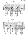
- Fig. 2 shows in the straight part of the plate cooler body 1 cooling tubes 2 with an elliptical cross section.
- the left half of FIG. 2 shows the transition of the cooling tubes from the circular to the elliptical cross section within the plate cooler body.
- cooling tubes 2 with an elongated round cross section. 4, the cooling tubes 2 are pivoted at an angle of approximately 45 ° in their distance from the hot side 4 of the plate cooler. This arrangement improves the temperature and voltage conditions in the plate cooler.
Landscapes
- Engineering & Computer Science (AREA)
- Chemical & Material Sciences (AREA)
- Manufacturing & Machinery (AREA)
- Materials Engineering (AREA)
- Metallurgy (AREA)
- Organic Chemistry (AREA)
- Furnace Housings, Linings, Walls, And Ceilings (AREA)
- Blast Furnaces (AREA)
- Heat-Exchange Devices With Radiators And Conduit Assemblies (AREA)
Abstract
Description
Die Erfindung betrifft einen Plattenkühler aus Gußmaterial mit eingegossenen Kühlrohren für die Wasserkühlung von metallurgischen öfen, insbesondere Hochöfen.The invention relates to a plate cooler made of cast material with cast-in cooling tubes for the water cooling of metallurgical furnaces, in particular blast furnaces.
Bekannte Plattenkühler bzw. "stave cooler" bestehen aus einem Gußeisenkörper, in welchem Stahlrohre angeordnet sind, durch die ein Kühlmittel, das heißt in den meisten Fällen Wasser oder ein Wasserdampf-WasserGemisch fließt. Der Querschnitt der Kühlrohre ist kreisförmig. Der Gußkörper des Plattenkühlers weist häufig an der dem Ofeninneren zugewandten Seite Aussparungen zur Einbringung feuerfesten Materials auf.Known plate coolers or "stave coolers" consist of a cast iron body, in which steel pipes are arranged, through which a coolant, that is to say in most cases water or a water vapor / water mixture, flows. The cross section of the cooling tubes is circular. The cast body of the plate cooler frequently has cutouts on the side facing the furnace interior for the introduction of refractory material.
Die bekannten Plattenkühler sind im Laufe der letzten 15 Jahre weiter entwickelt worden, um ihre Betriebssicherheit und thermische Belastbarkeit zu verbessern. Zur Erhöhung der thermischen Belastbarkeit hat man u.a. den Weg beschritten, den Durchmesser der Kühlrohre zu vergrößern, um dadurch das Verhältnis Kühlfläche zur Heizfläche zu erhöhen. Als Kühlfläche wurde die Mantelfläche der Kühlrohre im qeraden Teil innerhalb des Plattenkühlers bezeichnet, als Heizfläche die zum Ofeninneren zeigende Vorderseite des Plattenkühlers.The known plate coolers have been further developed over the past 15 years in order to improve their operational safety and thermal resilience. To increase the thermal resilience, followed the path of increasing the diameter of the cooling pipes, thereby increasing the ratio of the cooling surface to the heating surface. The outer surface of the cooling pipes in the right-hand part inside the plate cooler was designated as the cooling surface, and the front of the plate cooler facing the furnace interior was designated as the heating surface.
Kühlrohre in Plattenkühlern mit vergrößertem Durchmesser bewirken eine Absenkung der Plattenkühlertempera- turen bei gleichbleibender Wärmebelastung, oder sie haben eine Erhöhung der übertragbaren Wärmeströme bei gleichbleibenden Maximaltemperaturen zur Folge. Dies geschieht aus folgendem Grunde:
- 1. Der größere Kühlrohrdurchmesser beschneidet das logarithmische Temperaturprofil in der Rohrumgebung, und zwar im steilsten Teil.
- 2. Es wird die mit einem relativ hohen spezifischen Wärmedurchgangswiderstand behaftete Übergangszone Kühlrohr/Gußkörper vergrößert, so daß sich der integrale Wärmedurchgangswiderstand entsprechend verringert.
- 1. The larger cooling pipe diameter cuts the logarithmic temperature profile in the pipe environment, in the steepest part.
- 2. The cooling tube / cast body transition zone, which has a relatively high specific thermal resistance, is enlarged, so that the integral thermal resistance is reduced accordingly.
Die zuvor geschilderten WeiterentwicklungsmaBnahmen brachten zwar den erstrebten Erfolg, indem sich mit der Vergrößerung des Durchmessers der Kühlrohre die Kühlfläche proportional erhöhte, doch gleichzeitig wurde mit steigenden Kühlrohrdurchmesser der nuerschnitt der Kühlrohre quadratisch erhöht. Da nun bei der Wasserkühlung die Einhaltung einer bestimmten Wassergeschwindiqkeit erforderlich ist, um ein Eintreten von Filmsieden bei starker Belastung zu vermeiden, mußte die Wassergeschwindigkeit in den Kühlrohren mindestens 1,2 bis 1,5 m/sec. betragen und daher entsprechend dem vergrößerten Kühlrohrdurchmesser eine überproportional anwachsende Kühlwassermenge in Kauf genommen werden.The previously described further development measures brought the desired success by increasing the cooling surface proportionally with the increase in the diameter of the cooling tubes, but at the same time the cross section of the cooling tubes was increased square with increasing cooling tube diameter. Since a certain water speed is now required for water cooling in order to avoid the occurrence of film boiling under heavy loads, the water speed in the cooling pipes had to be at least 1.2 to 1.5 m / sec. amount and therefore a disproportionately increasing amount of cooling water must be accepted in accordance with the enlarged cooling tube diameter.
Aufgrund derart hoher Kühlwassermengen mußten die Zu-und Ablaufleitungsquerschnitte, die Rückkühlerabmessungen, die Pumpenabmessungen und Antriebsleistungen der Pumpen entsprechend vergrößert werden. Dies mußte geschehen, obgleich andererseits derart hohe Kühlwassermengen vom Wärmeangebot her gar nicht erforderlich sind, das heißt die Aufheizspanne des Kühlwassers ist bei weitem geringer als dies von der Wasserqualität her zulässig wäre.Due to such large amounts of cooling water, the inlet and outlet line cross sections, the recooler dimensions, the pump dimensions and drive powers of the pumps had to be increased accordingly. This had to be done, although on the other hand such high amounts of cooling water are not required from the supply of heat, that is to say the heating-up period of the cooling water is far less than would be permitted from the point of view of the water quality.
Aufgabe der Erfindung war es daher, einen Weg zu suchen, wie bei unveränderter Kühlfläche, d.h. unveränderter Oberfläche des Kühlrohres dessen Ouerschnitt verringert werden kann.The object of the invention was therefore to find a way, as with unchanged cooling surface, i.e. unchanged surface of the cooling tube whose cross section can be reduced.
Diese Aufgabe wird nach der Erfindung in der Weise gelöst, daß die Kühlrohre zumindest im geraden Teil innerhalb des Kühlers einen länglichrunden, insbesondere elliptischen oder ellipsenähnlichen Querschnitt aufweisen.This object is achieved according to the invention in such a way that the cooling tubes have an elongated, in particular elliptical or elliptical-like cross section, at least in the straight part within the cooler.
Weitere Ausgestaltungen der Erfindung sind Gegenstand der Unteransprüche.Further embodiments of the invention are the subject of the dependent claims.
Die Druckverlusterhöhung ist bei einem nicht kreisförmigen Querschnitt der Kühlrohre unbedeutend. So erhöht sich z.B. bei einer Wassergeschwindigkeit von 1,5 m/sec. und einem Übergang vom runden Rohr mit 76,1 mm Außendurchmesser und 6,3 mm Wandstärke zu einem elliptischen Rohr mit einem Achsenverhältnis (innen) 1 : 3 von 48 mm WS auf 66 mm WS je lfdm., d.h. um ca. 40 %. Bei einem 15 m langen Rohrstrang ergibt dieses einen zusätzlichen Druckverlust von nur etwa 270 mm WS. Dieser Mehrbetrag ist in der Praxis vernachlässigbar. Der Durchsatz an Wasser vermindert sich um 35 %.The pressure loss increase is insignificant in the case of a non-circular cross section of the cooling tubes. For example, at a water speed of 1.5 m / sec. and a transition from the round tube with 76.1 mm outside diameter and 6.3 mm wall thickness to an elliptical tube with an axial ratio (inside) of 1: 3 from 48 mm WS to 66 mm WS per running meter, i.e. by about 40%. With a 15 m long pipe string, this results in an additional pressure loss of only about 270 mm WS. In practice, this additional amount is negligible. The water throughput is reduced by 35%.
Da es ausreicht, wenn die Kühlrohre nur in ihrem geraden Teil innerhalb des Kühlers einen länglichrunden, elliptischen oder ellipsenähnlichen Querschnitt besitzen, während Kühlrohreinlauf und -auslauf einen kreisförmigen Querschnitt aufweisen, wird die Herstellung der Schweißverbindungen zur Außenverrohrung erleichtert.Since it is sufficient if the cooling pipes only have an elongated round, elliptical or elliptical-like cross section in their straight part within the cooler, while the cooling pipe inlet and outlet have a circular cross section, the production of the welded connections to the external piping is facilitated.
In der Zeichnung sind einige Ausführungsbeispiele der Erfindung dargestellt.In the drawing, some embodiments of the invention are shown.
Es zeigen:
- Fig. 1 einen Schnitt eines konventionellen Plattenkühlers mit kreisrunden Kühlrohren,
- Fig. 2 einen Schnitt eines erfindungsgemäßen Plattenkühlers mit Kühlrohren elliptischen Querschnitts,
- Fig. 3 einen Schnitt eines Plattenkühlers mit Kühlrohren länglichrunden Querschnitts,
- Fig. 4 einen Schnitt eines Plattenkühlers mit Kühlrohren länglichrunden Querschnitts, die winklig zur Heißseite geneigt sind und
- Fig. 5 in einem Schaubild die Änderung der Querschnittsflächen in Abhängigkeit vom Achsenverhältnis für abgeplattete Querschnitte.
- 1 shows a section of a conventional plate cooler with circular cooling tubes,
- 2 shows a section of a plate cooler according to the invention with cooling tubes of elliptical cross section,
- F ig. 3 shows a section of a plate cooler with cooling tubes having an elongated round cross section,
- Fi g . 4 shows a section of a plate cooler with cooling tubes having an elongated round cross section which are inclined at an angle to the hot side, and
- Fig. 5 is a graph showing the change in cross-sectional areas depending on the axial ratio for flattened cross-sections.
Nach Fig. 1 weisen die Kühlrohre 2, die in den Plattenkühlerkörper 1 eingegossen sind, einen kreisförmigen Querschnitt auf. Am Einlauf und Auslauf der Kühlrohre 2 in den Plattenkühlerkörper 1 sind diese von Schutzrohren 3, die ebenfalls eingegossen sind, umgeben. Mit 4 ist die dem metallurgischen Ofen zugewandte Heißseite des Plattenkühlers bezeichnet. Fig. 1 dokumentiert den Stand der Technik.1, the
Fig. 2 zeigt im geraden Teil des Plattenkühlerkörpers 1 Kühlrohre 2 mit elliptischem Querschnitt. Auf der linken Hälfte von Fig. 2 ist der Übergang der Kühlrohre vom kreisförmigen auf den elliptischen Querschnitt innerhalb des Plattenkühlerkörpers gezeigt.Fig. 2 shows in the straight part of the
Fig. 3 und 4 zeigen Anordnungen von Kühlrohren 2 mit länglichrundem Querschnitt. Gemäß Fig. 4 sind die Kühlrohre 2 in ihrem Abstand zur Heißseite 4 des Plattenkühlers in einem Winkel von ca. 45° geschwenkt angeordnet. Diese Anordnung verbessert die Temperatur- und Spannungsverhältnisse im Plattenkühler.3 and 4 show arrangements of
Claims (5)
dadurch gekennzeichnet,
daß die Kühlrohre (2) zumindest im geraden Teil innerhalb des Kühlers (1) einen länglichrunden, insbesondere elliptischen oder ellipsenähnlichen Querschnitt aufweisen.1. plate cooler made of cast material with cast-in cooling tubes for water cooling of metallurgical furnaces, in particular blast furnaces,
characterized,
that the cooling tubes (2), at least in the straight part within the cooler (1), have an elongated, in particular elliptical or elliptical-like cross section.
dadurch gekennzeichnet,
daß das Achsenverhältnis b:a beim länglichrunden Querschnitt zwischen 1 : 1,2 bis 1 : 15, vorzugsweise zwischen 1 : 3 bis 1 : 8 beträgt.2. plate cooler according to claim 1,
characterized,
that the axial ratio b: a is between 1: 1.2 to 1:15, preferably between 1: 3 to 1: 8 for the elongated round cross section.
dadurch gekennzeichnet,
daß die große Achse (5) des länglichrunden Querschnitts parallel zur Heißseite (4) des Plattenkühlers (1) eingegossen ist.3. plate cooler according to claims 1 and 2,
characterized,
that the large axis (5) of the elongated round cross-section is cast parallel to the hot side (4) of the plate cooler (1).
dadurch gekennzeichnet,
daß die große Achse (5) des länglichrunden Querschnitts in einem Winkel zwischen 1° und 45° geschwenkt zur Heißseite (4) des Plattenkühlers (1) eingegossen ist.4. plate cooler according to claims 1 and 2,
characterized,
that the large axis (5) of the elongated round cross section is pivoted at an angle between 1 ° and 45 ° to the hot side (4) of the plate cooler (1).
dadurch gekennzeichnet,
daß benachbart eingegossene Kühlrohre (2) in ihrem Abstand zur Heißseite (4) des Plattenkühlers (1) versetzt angeordnet sind.5. plate cooler according to claims 1 to 4,
characterized,
that adjacent cast-in cooling tubes (2) are offset in their distance from the hot side (4) of the plate cooler (1).
Priority Applications (1)
| Application Number | Priority Date | Filing Date | Title |
|---|---|---|---|
| AT84111336T ATE35287T1 (en) | 1983-11-03 | 1984-09-22 | PLATE COOLER FOR METALLURGICAL FURNACES, ESPECIALLY BLAST FURNACES. |
Applications Claiming Priority (2)
| Application Number | Priority Date | Filing Date | Title |
|---|---|---|---|
| DE3339734 | 1983-11-03 | ||
| DE3339734A DE3339734C1 (en) | 1983-11-03 | 1983-11-03 | Plate cooler for metallurgical furnaces, especially blast furnaces |
Publications (2)
| Publication Number | Publication Date |
|---|---|
| EP0144578A1 true EP0144578A1 (en) | 1985-06-19 |
| EP0144578B1 EP0144578B1 (en) | 1988-06-22 |
Family
ID=6213341
Family Applications (1)
| Application Number | Title | Priority Date | Filing Date |
|---|---|---|---|
| EP84111336A Expired EP0144578B1 (en) | 1983-11-03 | 1984-09-22 | Cooling panel for metallurgical furnaces, especially blast furnaces |
Country Status (3)
| Country | Link |
|---|---|
| EP (1) | EP0144578B1 (en) |
| AT (1) | ATE35287T1 (en) |
| DE (2) | DE3339734C1 (en) |
Cited By (6)
| Publication number | Priority date | Publication date | Assignee | Title |
|---|---|---|---|---|
| EP1156124A1 (en) * | 2000-05-19 | 2001-11-21 | KM Europa Metal Aktiengesellschaft | Cooling plate and method of producing |
| LU90644B1 (en) * | 2000-09-26 | 2002-03-27 | Wurth Paul Sa | Process for cooling a blast furnace comprises using cooling plates having a sturdy plate body with integrated cooling channels through which water can flow |
| EP1302551A1 (en) * | 2001-10-16 | 2003-04-16 | KM Europa Metal Aktiengesellschaft | Cooling plate for shaft furnace |
| US7537724B2 (en) | 2002-08-20 | 2009-05-26 | Siemens Vai Metals Technologies Gmbh & Co. | Cooling plate for metallurgic furnaces |
| WO2011157897A1 (en) | 2010-06-15 | 2011-12-22 | Upm-Kymmene Wood Oy | A flooring for a freight transportation vehicle or trailer and a method for forming a flooring to a freight transportation vehicle or trailer |
| CN117587178A (en) * | 2023-11-27 | 2024-02-23 | 秦冶工程技术(北京)有限责任公司 | Blast furnace cooling wall |
Citations (4)
| Publication number | Priority date | Publication date | Assignee | Title |
|---|---|---|---|---|
| FR2097192A1 (en) * | 1970-07-04 | 1972-03-03 | Ishikawajima Harima Heavy Ind | |
| EP0012132A1 (en) * | 1978-12-01 | 1980-06-11 | Arbed S.A. | Metallic cooling devices for industrial furnaces |
| DE2942121A1 (en) * | 1979-10-18 | 1981-04-30 | Klöckner-Humboldt-Deutz AG, 5000 Köln | OVEN PLANT, ESPECIALLY FOR MELTING ORE CONCENTRATE |
| FR2523488A1 (en) * | 1982-02-02 | 1983-09-23 | Inst Ochistke T | METHOD FOR MANUFACTURING METALLURGICAL OVEN COOLING PLATES AND COOLING PLATE MANUFACTURED BY SAID METHOD |
Family Cites Families (3)
| Publication number | Priority date | Publication date | Assignee | Title |
|---|---|---|---|---|
| DE125333C (en) * | ||||
| JPS5285004A (en) * | 1976-01-09 | 1977-07-15 | Sanyo Special Steel Co Ltd | Furnace wall for superhighhpower arc furnace for steel making |
| FR2371652A2 (en) * | 1976-11-23 | 1978-06-16 | Sofresid | COOLING PLATE FOR WALLS OF TANK OVENS, ESPECIALLY FOR HAUTS-FOURNEAUX |
-
1983
- 1983-11-03 DE DE3339734A patent/DE3339734C1/en not_active Expired
-
1984
- 1984-09-22 DE DE8484111336T patent/DE3472272D1/en not_active Expired
- 1984-09-22 AT AT84111336T patent/ATE35287T1/en active
- 1984-09-22 EP EP84111336A patent/EP0144578B1/en not_active Expired
Patent Citations (4)
| Publication number | Priority date | Publication date | Assignee | Title |
|---|---|---|---|---|
| FR2097192A1 (en) * | 1970-07-04 | 1972-03-03 | Ishikawajima Harima Heavy Ind | |
| EP0012132A1 (en) * | 1978-12-01 | 1980-06-11 | Arbed S.A. | Metallic cooling devices for industrial furnaces |
| DE2942121A1 (en) * | 1979-10-18 | 1981-04-30 | Klöckner-Humboldt-Deutz AG, 5000 Köln | OVEN PLANT, ESPECIALLY FOR MELTING ORE CONCENTRATE |
| FR2523488A1 (en) * | 1982-02-02 | 1983-09-23 | Inst Ochistke T | METHOD FOR MANUFACTURING METALLURGICAL OVEN COOLING PLATES AND COOLING PLATE MANUFACTURED BY SAID METHOD |
Non-Patent Citations (1)
| Title |
|---|
| SOVIET INVENTIONS ILLUSTRATED, Woche 51, 8. Februar 1984; & SU - A - 267 060 (FERR METAL EFFL PURIF) 23.02.1983 * |
Cited By (6)
| Publication number | Priority date | Publication date | Assignee | Title |
|---|---|---|---|---|
| EP1156124A1 (en) * | 2000-05-19 | 2001-11-21 | KM Europa Metal Aktiengesellschaft | Cooling plate and method of producing |
| LU90644B1 (en) * | 2000-09-26 | 2002-03-27 | Wurth Paul Sa | Process for cooling a blast furnace comprises using cooling plates having a sturdy plate body with integrated cooling channels through which water can flow |
| EP1302551A1 (en) * | 2001-10-16 | 2003-04-16 | KM Europa Metal Aktiengesellschaft | Cooling plate for shaft furnace |
| US7537724B2 (en) | 2002-08-20 | 2009-05-26 | Siemens Vai Metals Technologies Gmbh & Co. | Cooling plate for metallurgic furnaces |
| WO2011157897A1 (en) | 2010-06-15 | 2011-12-22 | Upm-Kymmene Wood Oy | A flooring for a freight transportation vehicle or trailer and a method for forming a flooring to a freight transportation vehicle or trailer |
| CN117587178A (en) * | 2023-11-27 | 2024-02-23 | 秦冶工程技术(北京)有限责任公司 | Blast furnace cooling wall |
Also Published As
| Publication number | Publication date |
|---|---|
| DE3472272D1 (en) | 1988-07-28 |
| EP0144578B1 (en) | 1988-06-22 |
| ATE35287T1 (en) | 1988-07-15 |
| DE3339734C1 (en) | 1985-03-14 |
Similar Documents
| Publication | Publication Date | Title |
|---|---|---|
| DE2552679A1 (en) | HEAT TRANSFER PIPE | |
| DD140281A5 (en) | COOLED ARC FOAM COVER | |
| DE2127448B2 (en) | Cooling element, in particular plate cooler, for blast furnaces | |
| DE2112180C3 (en) | Cooled lance | |
| EP0144578A1 (en) | Cooling panel for metallurgical furnaces, especially blast furnaces | |
| DE2822918B2 (en) | Support rod for a neutron absorber rod in a nuclear reactor | |
| DE2425159C3 (en) | Cooler for blast furnace evaporative cooling | |
| DE2808686A1 (en) | GAS-TIGHT FURNACE WALL FOR AN INDUSTRIAL FURNACE | |
| DE2734922A1 (en) | METHOD AND DEVICE FOR COOLING EXHAUST MANIFOLD | |
| DE2144348A1 (en) | Flow device for liquids | |
| DE2734031C2 (en) | Mobile wet steam once-through steam generator | |
| DE3538515C2 (en) | ||
| CH685332A5 (en) | Continuous casting. | |
| DE2135668A1 (en) | Inflating oxygen converter | |
| EP0085461A1 (en) | Liquid-cooled side walls for electric-arc furnaces | |
| EP0837144A1 (en) | Cooling panel for shaft furnace | |
| DE2928964A1 (en) | Cooled door frame on steelworks furnaces - esp. open hearth furnaces, where frame contains pipes through which cooling water is circulated | |
| DE69910783T2 (en) | WATER-COOLED RUST FOR COMBUSTION PLANT | |
| DE3201607A1 (en) | COOKING OVEN BATTERY | |
| EP0130361A2 (en) | Heat exchanger end palte with arrangement for cooling | |
| DE694410C (en) | Flue gas feed water preheater made of narrow finned tubes made of high-quality construction material | |
| EP0033093A2 (en) | Process for dry cooling of coke | |
| CH226310A (en) | Heat exchanger. | |
| DE2355264C3 (en) | Furnaces for hot-dip galvanizing of metallic objects, in particular wires and strips | |
| DE3115930A1 (en) | STEEL OVENS FOR WARMING STEEL |
Legal Events
| Date | Code | Title | Description |
|---|---|---|---|
| PUAI | Public reference made under article 153(3) epc to a published international application that has entered the european phase |
Free format text: ORIGINAL CODE: 0009012 |
|
| AK | Designated contracting states |
Designated state(s): AT BE DE FR GB IT NL SE |
|
| 17P | Request for examination filed |
Effective date: 19851001 |
|
| RAP1 | Party data changed (applicant data changed or rights of an application transferred) |
Owner name: MAN GUTEHOFFNUNGSHUETTE GMBH |
|
| 17Q | First examination report despatched |
Effective date: 19861014 |
|
| D17Q | First examination report despatched (deleted) | ||
| GRAA | (expected) grant |
Free format text: ORIGINAL CODE: 0009210 |
|
| AK | Designated contracting states |
Kind code of ref document: B1 Designated state(s): AT BE DE FR GB IT NL SE |
|
| REF | Corresponds to: |
Ref document number: 35287 Country of ref document: AT Date of ref document: 19880715 Kind code of ref document: T |
|
| ITF | It: translation for a ep patent filed | ||
| REF | Corresponds to: |
Ref document number: 3472272 Country of ref document: DE Date of ref document: 19880728 |
|
| ET | Fr: translation filed | ||
| GBT | Gb: translation of ep patent filed (gb section 77(6)(a)/1977) | ||
| BECN | Be: change of holder's name |
Effective date: 19880622 |
|
| PLBE | No opposition filed within time limit |
Free format text: ORIGINAL CODE: 0009261 |
|
| STAA | Information on the status of an ep patent application or granted ep patent |
Free format text: STATUS: NO OPPOSITION FILED WITHIN TIME LIMIT |
|
| RAP2 | Party data changed (patent owner data changed or rights of a patent transferred) |
Owner name: MAN GUTEHOFFNUNGSHUETTE AKTIENGESELLSCHAFT |
|
| 26N | No opposition filed | ||
| NLT2 | Nl: modifications (of names), taken from the european patent patent bulletin |
Owner name: MAN GUTEHOFFNUNGSHUETTE AKTIENGESELLSCHAFT TE OBER |
|
| ITTA | It: last paid annual fee | ||
| EAL | Se: european patent in force in sweden |
Ref document number: 84111336.8 |
|
| REG | Reference to a national code |
Ref country code: FR Ref legal event code: TP |
|
| REG | Reference to a national code |
Ref country code: GB Ref legal event code: 732E |
|
| PGFP | Annual fee paid to national office [announced via postgrant information from national office to epo] |
Ref country code: GB Payment date: 19980814 Year of fee payment: 15 |
|
| PGFP | Annual fee paid to national office [announced via postgrant information from national office to epo] |
Ref country code: FR Payment date: 19980821 Year of fee payment: 15 Ref country code: DE Payment date: 19980821 Year of fee payment: 15 |
|
| PGFP | Annual fee paid to national office [announced via postgrant information from national office to epo] |
Ref country code: SE Payment date: 19980824 Year of fee payment: 15 Ref country code: AT Payment date: 19980824 Year of fee payment: 15 |
|
| PGFP | Annual fee paid to national office [announced via postgrant information from national office to epo] |
Ref country code: NL Payment date: 19980827 Year of fee payment: 15 |
|
| PGFP | Annual fee paid to national office [announced via postgrant information from national office to epo] |
Ref country code: BE Payment date: 19980908 Year of fee payment: 15 |
|
| NLS | Nl: assignments of ep-patents |
Owner name: SMS SCHLOEMANN-SIEMAG AKTIENGESELLSCHAFT;MAN GUTEH |
|
| PG25 | Lapsed in a contracting state [announced via postgrant information from national office to epo] |
Ref country code: GB Free format text: LAPSE BECAUSE OF NON-PAYMENT OF DUE FEES Effective date: 19990922 Ref country code: AT Free format text: LAPSE BECAUSE OF NON-PAYMENT OF DUE FEES Effective date: 19990922 |
|
| PG25 | Lapsed in a contracting state [announced via postgrant information from national office to epo] |
Ref country code: SE Free format text: THE PATENT HAS BEEN ANNULLED BY A DECISION OF A NATIONAL AUTHORITY Effective date: 19990929 |
|
| PG25 | Lapsed in a contracting state [announced via postgrant information from national office to epo] |
Ref country code: BE Free format text: LAPSE BECAUSE OF NON-PAYMENT OF DUE FEES Effective date: 19990930 |
|
| BERE | Be: lapsed |
Owner name: SMS SCHLOEMANN-SIEMAG A.G. Effective date: 19990930 |
|
| PG25 | Lapsed in a contracting state [announced via postgrant information from national office to epo] |
Ref country code: NL Free format text: LAPSE BECAUSE OF NON-PAYMENT OF DUE FEES Effective date: 20000401 |
|
| GBPC | Gb: european patent ceased through non-payment of renewal fee |
Effective date: 19990922 |
|
| EUG | Se: european patent has lapsed |
Ref document number: 84111336.8 |
|
| PG25 | Lapsed in a contracting state [announced via postgrant information from national office to epo] |
Ref country code: FR Free format text: LAPSE BECAUSE OF NON-PAYMENT OF DUE FEES Effective date: 20000531 |
|
| NLV4 | Nl: lapsed or anulled due to non-payment of the annual fee |
Effective date: 20000401 |
|
| PG25 | Lapsed in a contracting state [announced via postgrant information from national office to epo] |
Ref country code: DE Free format text: LAPSE BECAUSE OF NON-PAYMENT OF DUE FEES Effective date: 20000701 |
|
| REG | Reference to a national code |
Ref country code: FR Ref legal event code: ST |