EP0144259A2 - Kompaktes Servolenksystem für ein Kraftfahrzeug - Google Patents
Kompaktes Servolenksystem für ein Kraftfahrzeug Download PDFInfo
- Publication number
- EP0144259A2 EP0144259A2 EP84402244A EP84402244A EP0144259A2 EP 0144259 A2 EP0144259 A2 EP 0144259A2 EP 84402244 A EP84402244 A EP 84402244A EP 84402244 A EP84402244 A EP 84402244A EP 0144259 A2 EP0144259 A2 EP 0144259A2
- Authority
- EP
- European Patent Office
- Prior art keywords
- steering mechanism
- power steering
- rack
- mechanism according
- housing
- Prior art date
- Legal status (The legal status is an assumption and is not a legal conclusion. Google has not performed a legal analysis and makes no representation as to the accuracy of the status listed.)
- Granted
Links
Images


Classifications
-
- B—PERFORMING OPERATIONS; TRANSPORTING
- B62—LAND VEHICLES FOR TRAVELLING OTHERWISE THAN ON RAILS
- B62D—MOTOR VEHICLES; TRAILERS
- B62D5/00—Power-assisted or power-driven steering
- B62D5/06—Power-assisted or power-driven steering fluid, i.e. using a pressurised fluid for most or all the force required for steering a vehicle
- B62D5/20—Power-assisted or power-driven steering fluid, i.e. using a pressurised fluid for most or all the force required for steering a vehicle specially adapted for particular type of steering gear or particular application
- B62D5/22—Power-assisted or power-driven steering fluid, i.e. using a pressurised fluid for most or all the force required for steering a vehicle specially adapted for particular type of steering gear or particular application for rack-and-pinion type
Definitions
- the present invention relates to power steering mechanisms for a motor vehicle and, more particularly, a power steering mechanism of the type comprising a fixed steering box in which is arranged a cooperating pinion and rack assembly, the pinion being intended to be connected.
- a mechanism input control member a pressurized fluid assistance assembly comprising a fixed piston, secured to the housing by a hollow rod, and a movable cylinder coupled elastically to the rack and delimiting a first and a second pressure chambers on either side of the piston, and a distribution valve means actuable by the inlet control member for selectively supplying pressurized fluid to said first and second chambers via fluid passages provided in the hollow stem.
- a mechanism of this type is described in document FR-A-2 357 413.
- a cooperating piston / cylinder assembly. assistance arranged in parallel with the fixed steering box, outside of it.
- this arrangement has the drawbacks of increasing the transverse dimensions of the mechanism, making it heavier, / increasing the number of sliding zones to be protected.
- the rack slides, by means of tubular bearings, in the fixed steering box which must be machined with precision for this purpose, the junction between the rack and the movable assistance cylinder taking place by means of these sliding bearings.
- the object of the present invention is to propose an assisted steering mechanism of the above-mentioned type, of particularly compact and robust configuration, low manufacturing costs and making it possible to use a housing which is not internally machined and a simplified rack which does not require machining. very precise.
- the housing has a general tubular configuration with opposite end walls, the hollow rod being disposed in the housing between these end walls, the rack being resiliently mounted on the cylinder. mobile also integrated in the housing.
- supports elastic are provided between the rack and the movable cylinder, the rack being advantageously held at its ends, on this movable cylinder, by arches integral with the movable cylinder.
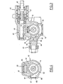
- the power steering mechanism comprises a steering box, generally designated by the reference 10, intended to be fixed to a fixed part of the chassis of a motor vehicle, and advantageously made in foundry.
- the steering box 10 is composed of a tubular main body part 11 on the open ends of which there are attached cup-shaped ends (12, 12 ') each comprising a bottom (13, 13'), these bottoms forming the axially opposite end walls of the housing 10. Between these funds extends a hollow rod 14 having ends sealingly passing through the funds 13 and 13 ', by means of which the rod is fixed to the funds 13 and 13' and on which are reported fittings 140, 140 'for connection to pipes for supplying pressurized fluid 141, 141'.
- An annular piston 16 is fixed centrally on the hollow rod 14 which comprises, in line with the piston 16, a watertight partition 17 separating the inner conduit 15 from the hollow rod 14 into two portions opening outward respectively 'rad ux by means of passages / 18 and 19 formed on either side of the piston 16.
- a cylinder assembly constituted by a tubular cylinder body 50, cooperating with the periphery of the piston 16, and two end sliding bearings 51 cooperating with sealed sliding with the periphery of the hollow rod 14 and thus defining, on either side of the fixed piston 16, two actuation chambers 58 and 59 supplied by the passages 18 and 19.
- the rack block 30 is floatingly mounted transversely on the cylinder body 50.
- the rack body 30 has ends 31 of width and / each reduced received / between the side walls of a gutter portion 53 of a hoop 52 fixed on the corresponding end of the cylinder body 50.
- the axially opposite end zones of the rack body 30 have curved side walls 32, with their convexity facing outwards, while these ends end in legs of reduced thickness immobilized by crosspieces 54 connecting the facing walls 53 of the arch 52.
- the substantially flat lower face of the rack body 30 comprises a number of cylindrical housings 33 axially distant from each other and in which elastic elements 34 are received and positioned by the through which the rack block 30 rests on the cylinder body 50.
- the elastic elements each consist of a stack of elastic washers which may alternatively be replaced by possibly reinforced elastomer blocks.
- the cylinder body 50 is joined to the members 60 for connection to connecting rods 61 for orienting the steerable wheels of the vehicle, these connection members extending to guide and slide through an oblong window 61 formed in a side wall 62 of the main body part 11 of the housing 10.
- the pinion 20 is in turn connected, by means of a dead travel coupling and a distribution valve 40 - advantageously housed in a transverse tubular extension 41 of the main body part 11 of the housing - to a shaft 42 for controlling the input of the mechanism intended to be connected to the vehicle steering wheel.
- the distribution valve 40 is for example of the star rotor and C-spring type described in document EP-A-0 077 710, its distribution orifices being connected to the tubulars 141 and 141 '.
- the transverse floating connection between the rack body 30 and the cylinder body 50 makes it possible to prevent imperfections in the teeth of the rack from being translated into stresses. exerted on the sliding bearings 51 of the cylinder 50 nor, conversely, due in addition to the "ball joint" connection between the ends of the rack block 30 and the gutters 53 of the arches 52, the possible angular movements, around its axis, of the cylinder 50 - resulting in particular from the imperfections of guidance between the connection members 60 and the walls of the longitudinal window 61 - are not transmitted to the toothed junction between the rack 30 and the pinion 20, in an arrangement thus greatly limiting the constraints likely to appear in the active elements of the mechanism.
- the cylinder body 50 bears below against a profiled elastic support member 57 mounted in the main body part 11 of the housing 10 directly above the pinion 20 (and of the fixed piston 16).
- connection members 60 comprise an inner block 63 fixed to the cylinder body 50, received slidingly in the window 61 and extending outwardly by a fork-shaped portion 64 in which an outer block is fixed 65 carrying the ball joints for connecting the rods 61.
- the two blocks 63 and 64 provide between them a passage of rectangular section 66 with a profile gradually shifting from the window 61 and through which passes a flexible sealing strip 67 fixed by its ends, at 68, to the areas of the main body part 11 axially delimiting the window 61, and the lateral edges of which are received, in a removable manner, in longitudinal grooves 68 formed in the walls facing the oblong window 61.
- the strip 67 forced to pass through the passage 66, emerges from one side of its grooves 68 to recover its housing in these grooves downstream of the blocks 63 and 65.
- the inner block 63 of the connection members 60 comprises a piece forming a cursor 69 cooperating with the complementary ends of two sails with longitudinal undulations 67 ′ in order to release and gradually reconstitute a connection 670 of the zipper type when the members move connection 60 along the oblong window 61, the webs 67 'being fixed, by their opposite ends on either side of the window 61 / to the side wall 62 of the main body part 11 of the housing 10.
Landscapes
- Engineering & Computer Science (AREA)
- Chemical & Material Sciences (AREA)
- Combustion & Propulsion (AREA)
- Transportation (AREA)
- Mechanical Engineering (AREA)
- Power Steering Mechanism (AREA)
Applications Claiming Priority (2)
| Application Number | Priority Date | Filing Date | Title |
|---|---|---|---|
| ES527577 | 1983-11-18 | ||
| ES527577A ES8500828A1 (es) | 1983-11-18 | 1983-11-18 | Mecanismo de direccion asistida para automoviles |
Publications (3)
| Publication Number | Publication Date |
|---|---|
| EP0144259A2 true EP0144259A2 (de) | 1985-06-12 |
| EP0144259A3 EP0144259A3 (en) | 1986-06-04 |
| EP0144259B1 EP0144259B1 (de) | 1988-02-24 |
Family
ID=8486514
Family Applications (1)
| Application Number | Title | Priority Date | Filing Date |
|---|---|---|---|
| EP84402244A Expired EP0144259B1 (de) | 1983-11-18 | 1984-11-07 | Kompaktes Servolenksystem für ein Kraftfahrzeug |
Country Status (7)
| Country | Link |
|---|---|
| US (1) | US4629026A (de) |
| EP (1) | EP0144259B1 (de) |
| JP (1) | JPS60116563A (de) |
| AU (1) | AU562609B2 (de) |
| BR (1) | BR8405887A (de) |
| DE (1) | DE3469424D1 (de) |
| ES (1) | ES8500828A1 (de) |
Cited By (2)
| Publication number | Priority date | Publication date | Assignee | Title |
|---|---|---|---|---|
| WO1990011921A1 (de) * | 1989-04-07 | 1990-10-18 | Zahnradfabrik Friedrichshafen Ag | Zahnstangen-hilfskraftlenkung, für - insbesondere schwere - kraftfahrzeuge |
| WO1996022213A1 (de) * | 1995-01-20 | 1996-07-25 | Trw Fahrwerksysteme Gmbh & Co. Kg | Lenkgetriebe |
Families Citing this family (10)
| Publication number | Priority date | Publication date | Assignee | Title |
|---|---|---|---|---|
| ES8605734A1 (es) * | 1985-01-14 | 1986-04-01 | Bendiberica Sa | Perfeccionamientos en mecanismos de direccion asistida com- pactos para vehiculos automoviles |
| GB2196090B (en) * | 1986-09-20 | 1990-05-16 | Rolls Royce Motors Ltd | Rack and pinion gear |
| US4953653A (en) * | 1989-01-17 | 1990-09-04 | Trw Inc. | Fluid power assist rack and pinion steering gear with end-take-off |
| US5213175A (en) * | 1991-05-20 | 1993-05-25 | Trw Inc. | Reduced length rack and pinion steering assembly |
| US5251717A (en) * | 1991-06-18 | 1993-10-12 | Trw Inc. | Hydraulic rack and pinion steering assembly |
| US6176343B1 (en) | 1997-12-15 | 2001-01-23 | Trw Inc. | Vehicle steering apparatus |
| US6793471B2 (en) * | 2002-05-09 | 2004-09-21 | Sergei Latyshev | Fluid machine |
| DE10336628A1 (de) * | 2003-08-05 | 2005-03-24 | Thyssenkrupp Presta Steertec Gmbh | Lenkgetriebe für ein Kraftfahrzeug |
| JP2006335303A (ja) * | 2005-06-06 | 2006-12-14 | Kayaba Ind Co Ltd | パワーステアリング装置 |
| CN102167077A (zh) * | 2011-03-18 | 2011-08-31 | 华南理工大学 | 一种汽车主动转向器 |
Citations (7)
| Publication number | Priority date | Publication date | Assignee | Title |
|---|---|---|---|---|
| CH344316A (de) * | 1955-05-06 | 1960-01-31 | Auto Union Gmbh | Lenkvorrichtung für Kraftfahrzeuge |
| US3605934A (en) * | 1968-07-01 | 1971-09-20 | Adwest Eng Ltd | Steering mechanism for motor vehicles |
| FR2122236A5 (de) * | 1971-01-16 | 1972-08-25 | Burman Et Sons Ltd | |
| FR2186914A5 (de) * | 1972-05-31 | 1974-01-11 | Ehrenreich & Cie A | |
| FR2357413A1 (fr) * | 1976-07-07 | 1978-02-03 | Cam Gears Ltd | Mecanisme a pignon et cremaillere pour direction assistee de vehicule automobile |
| US4141432A (en) * | 1977-10-05 | 1979-02-27 | The Bendix Corporation | Rack and pinion steering device |
| WO1981000239A1 (en) * | 1979-07-12 | 1981-02-05 | Zahnradfabrik Friedrichshafen | Control mechanism with a rack |
Family Cites Families (5)
| Publication number | Priority date | Publication date | Assignee | Title |
|---|---|---|---|---|
| US1960379A (en) * | 1933-12-01 | 1934-05-29 | Neil F Havens | Hydraulic crowding device |
| GB1307791A (en) * | 1971-01-20 | 1973-02-21 | British Leyland Truck & Bus | Rack and pinion steering gear |
| SE368802B (de) * | 1972-12-08 | 1974-07-22 | Volvo Flygmotor Ab | |
| DE3118254C2 (de) * | 1981-05-08 | 1986-06-26 | Zahnradfabrik Friedrichshafen Ag, 7990 Friedrichshafen | Zahnstangenlenkgetriebe, insbesondere für Kraftfahrzeuge |
| US4428450A (en) * | 1982-09-15 | 1984-01-31 | General Motors Corporation | Rack and pinion steering gear |
-
1983
- 1983-11-18 ES ES527577A patent/ES8500828A1/es not_active Expired
-
1984
- 1984-11-05 US US06/668,438 patent/US4629026A/en not_active Expired - Fee Related
- 1984-11-07 DE DE8484402244T patent/DE3469424D1/de not_active Expired
- 1984-11-07 EP EP84402244A patent/EP0144259B1/de not_active Expired
- 1984-11-14 BR BR8405887A patent/BR8405887A/pt not_active IP Right Cessation
- 1984-11-15 JP JP59239589A patent/JPS60116563A/ja active Granted
- 1984-11-16 AU AU35498/84A patent/AU562609B2/en not_active Ceased
Patent Citations (7)
| Publication number | Priority date | Publication date | Assignee | Title |
|---|---|---|---|---|
| CH344316A (de) * | 1955-05-06 | 1960-01-31 | Auto Union Gmbh | Lenkvorrichtung für Kraftfahrzeuge |
| US3605934A (en) * | 1968-07-01 | 1971-09-20 | Adwest Eng Ltd | Steering mechanism for motor vehicles |
| FR2122236A5 (de) * | 1971-01-16 | 1972-08-25 | Burman Et Sons Ltd | |
| FR2186914A5 (de) * | 1972-05-31 | 1974-01-11 | Ehrenreich & Cie A | |
| FR2357413A1 (fr) * | 1976-07-07 | 1978-02-03 | Cam Gears Ltd | Mecanisme a pignon et cremaillere pour direction assistee de vehicule automobile |
| US4141432A (en) * | 1977-10-05 | 1979-02-27 | The Bendix Corporation | Rack and pinion steering device |
| WO1981000239A1 (en) * | 1979-07-12 | 1981-02-05 | Zahnradfabrik Friedrichshafen | Control mechanism with a rack |
Cited By (3)
| Publication number | Priority date | Publication date | Assignee | Title |
|---|---|---|---|---|
| WO1990011921A1 (de) * | 1989-04-07 | 1990-10-18 | Zahnradfabrik Friedrichshafen Ag | Zahnstangen-hilfskraftlenkung, für - insbesondere schwere - kraftfahrzeuge |
| WO1996022213A1 (de) * | 1995-01-20 | 1996-07-25 | Trw Fahrwerksysteme Gmbh & Co. Kg | Lenkgetriebe |
| US5842537A (en) * | 1995-01-20 | 1998-12-01 | Trw Fahrwerksysteme Gmbh & Co. Kg | Steering gear |
Also Published As
| Publication number | Publication date |
|---|---|
| EP0144259B1 (de) | 1988-02-24 |
| BR8405887A (pt) | 1985-09-17 |
| ES527577A0 (es) | 1984-11-01 |
| AU3549884A (en) | 1985-05-23 |
| JPS60116563A (ja) | 1985-06-24 |
| JPH0554470B2 (de) | 1993-08-12 |
| AU562609B2 (en) | 1987-06-11 |
| EP0144259A3 (en) | 1986-06-04 |
| US4629026A (en) | 1986-12-16 |
| ES8500828A1 (es) | 1984-11-01 |
| DE3469424D1 (en) | 1988-03-31 |
Similar Documents
| Publication | Publication Date | Title |
|---|---|---|
| EP0144259B1 (de) | Kompaktes Servolenksystem für ein Kraftfahrzeug | |
| FR2510506A1 (fr) | Systeme de direction permettant le braquage des roues avant et des roues arriere d'un vehicule | |
| WO2001016473A1 (fr) | Dispositif de regulation de l'ecoulement dans une portion de conduit ou un passage et collecteur comprenant un tel dispositif | |
| EP0805278B1 (de) | Pneumatisch betätigte Einrichtung | |
| EP2751437A1 (de) | Vorrichtung zum verbinden einer lenksäule mit einem lenkgetriebegehäuse | |
| EP0066507B1 (de) | Hydraulischer Rotationsverteiler für eine hydraulische Antriebseinrichtung | |
| EP0336789A1 (de) | Elastische Lagerung mit hydraulischer Versteifung | |
| EP0119922B1 (de) | Zahnstangenservolenkung, insbesondere mit zentralem Abtrieb | |
| EP0107997A1 (de) | Bremskraftverstärker | |
| EP0188158B1 (de) | Kompaktservolenkungsmechanismus für Kraftfahrzeug | |
| EP0136234B1 (de) | Zahnstangen-Servolenkeinrichtung | |
| FR2620997A1 (fr) | Dispositif d'accouplement pour une colonne de direction et vehicule equipe d'un tel dispositif | |
| FR2549793A1 (fr) | Appareil de direction assistee pour tracteur | |
| EP0112249B1 (de) | Servolenkung für Fahrzeuge | |
| FR2505763A1 (fr) | Dispositif de direction assistee d'un vehicule | |
| EP0181797B1 (de) | Drehbeweglicher Hydraulikverteiler, insbesondere für Servolenkvorrichtung | |
| EP0873922B1 (de) | Motorgetriebe für Scheibenwischer eines Kraftfahrzeuges mit einer Waschwasser-Rohrleitung | |
| EP0119923A1 (de) | Servolenkung mit zentralem Abtrieb | |
| EP1047591A1 (de) | Fahrzeug mit einem rumpf und mit einziehbaren rädern | |
| EP3784901B1 (de) | Hydraulische anordnung für ein gelenktes rad eines fahrzeuges | |
| EP0075519B1 (de) | Antriebsmechanismus mit Fluidhilfe, insbesondere für Kraftfahrzeugservolenkungssystem | |
| EP0743237B1 (de) | Vorderes Fahrgestell an der Karosserie eines Kraftfahrzeuges | |
| FR2504485A1 (fr) | Dispositif de direction assistee a pignon et cremaillere pour vehicules automobiles | |
| EP0136233B1 (de) | Kompakt-Servolenkungs-Mechanismus für Kraftfahrzeug | |
| FR2730180A1 (fr) | Perfectionnement pour dispositif de serrage du type comprenant un levier actionne par un piston |
Legal Events
| Date | Code | Title | Description |
|---|---|---|---|
| PUAI | Public reference made under article 153(3) epc to a published international application that has entered the european phase |
Free format text: ORIGINAL CODE: 0009012 |
|
| 17P | Request for examination filed |
Effective date: 19841115 |
|
| AK | Designated contracting states |
Designated state(s): DE FR GB IT |
|
| PUAL | Search report despatched |
Free format text: ORIGINAL CODE: 0009013 |
|
| RHK1 | Main classification (correction) |
Ipc: B62D 5/12 |
|
| AK | Designated contracting states |
Kind code of ref document: A3 Designated state(s): DE FR GB IT |
|
| RAP1 | Party data changed (applicant data changed or rights of an application transferred) |
Owner name: BENDIX ESPANA S.A. |
|
| 17Q | First examination report despatched |
Effective date: 19870326 |
|
| ITF | It: translation for a ep patent filed |
Owner name: ING. ZINI MARANESI & C. S.R.L. |
|
| GRAA | (expected) grant |
Free format text: ORIGINAL CODE: 0009210 |
|
| AK | Designated contracting states |
Kind code of ref document: B1 Designated state(s): DE FR GB IT |
|
| GBT | Gb: translation of ep patent filed (gb section 77(6)(a)/1977) | ||
| REF | Corresponds to: |
Ref document number: 3469424 Country of ref document: DE Date of ref document: 19880331 |
|
| PLBE | No opposition filed within time limit |
Free format text: ORIGINAL CODE: 0009261 |
|
| STAA | Information on the status of an ep patent application or granted ep patent |
Free format text: STATUS: NO OPPOSITION FILED WITHIN TIME LIMIT |
|
| 26N | No opposition filed | ||
| ITTA | It: last paid annual fee | ||
| PGFP | Annual fee paid to national office [announced via postgrant information from national office to epo] |
Ref country code: GB Payment date: 19961009 Year of fee payment: 13 |
|
| PGFP | Annual fee paid to national office [announced via postgrant information from national office to epo] |
Ref country code: FR Payment date: 19961113 Year of fee payment: 13 |
|
| PGFP | Annual fee paid to national office [announced via postgrant information from national office to epo] |
Ref country code: DE Payment date: 19961128 Year of fee payment: 13 |
|
| PG25 | Lapsed in a contracting state [announced via postgrant information from national office to epo] |
Ref country code: GB Free format text: LAPSE BECAUSE OF NON-PAYMENT OF DUE FEES Effective date: 19971107 |
|
| PG25 | Lapsed in a contracting state [announced via postgrant information from national office to epo] |
Ref country code: FR Free format text: THE PATENT HAS BEEN ANNULLED BY A DECISION OF A NATIONAL AUTHORITY Effective date: 19971130 |
|
| GBPC | Gb: european patent ceased through non-payment of renewal fee |
Effective date: 19971107 |
|
| PG25 | Lapsed in a contracting state [announced via postgrant information from national office to epo] |
Ref country code: DE Free format text: LAPSE BECAUSE OF NON-PAYMENT OF DUE FEES Effective date: 19980801 |
|
| REG | Reference to a national code |
Ref country code: FR Ref legal event code: ST |