EP0143813B1 - Device for the representation on condylar motions of a patient and their simulation - Google Patents
Device for the representation on condylar motions of a patient and their simulation Download PDFInfo
- Publication number
- EP0143813B1 EP0143813B1 EP84901946A EP84901946A EP0143813B1 EP 0143813 B1 EP0143813 B1 EP 0143813B1 EP 84901946 A EP84901946 A EP 84901946A EP 84901946 A EP84901946 A EP 84901946A EP 0143813 B1 EP0143813 B1 EP 0143813B1
- Authority
- EP
- European Patent Office
- Prior art keywords
- articulator
- recording
- teeth
- condylar
- jaw
- Prior art date
- Legal status (The legal status is an assumption and is not a legal conclusion. Google has not performed a legal analysis and makes no representation as to the accuracy of the status listed.)
- Expired
Links
Images

Classifications
-
- A—HUMAN NECESSITIES
- A61—MEDICAL OR VETERINARY SCIENCE; HYGIENE
- A61C—DENTISTRY; APPARATUS OR METHODS FOR ORAL OR DENTAL HYGIENE
- A61C19/00—Dental auxiliary appliances
- A61C19/04—Measuring instruments specially adapted for dentistry
- A61C19/045—Measuring instruments specially adapted for dentistry for recording mandibular movement, e.g. face bows
-
- A—HUMAN NECESSITIES
- A61—MEDICAL OR VETERINARY SCIENCE; HYGIENE
- A61C—DENTISTRY; APPARATUS OR METHODS FOR ORAL OR DENTAL HYGIENE
- A61C11/00—Dental articulators, i.e. for simulating movement of the temporo-mandibular joints; Articulation forms or mouldings
- A61C11/02—Dental articulators, i.e. for simulating movement of the temporo-mandibular joints; Articulation forms or mouldings characterised by the arrangement, location or type of the hinge means ; Articulators with pivots
- A61C11/022—Dental articulators, i.e. for simulating movement of the temporo-mandibular joints; Articulation forms or mouldings characterised by the arrangement, location or type of the hinge means ; Articulators with pivots with two adjustable pivoting points, e.g. Argon-type articulators
-
- A—HUMAN NECESSITIES
- A61—MEDICAL OR VETERINARY SCIENCE; HYGIENE
- A61C—DENTISTRY; APPARATUS OR METHODS FOR ORAL OR DENTAL HYGIENE
- A61C11/00—Dental articulators, i.e. for simulating movement of the temporo-mandibular joints; Articulation forms or mouldings
- A61C11/005—Dental articulators, i.e. for simulating movement of the temporo-mandibular joints; Articulation forms or mouldings with tracing devices
-
- A—HUMAN NECESSITIES
- A61—MEDICAL OR VETERINARY SCIENCE; HYGIENE
- A61C—DENTISTRY; APPARATUS OR METHODS FOR ORAL OR DENTAL HYGIENE
- A61C11/00—Dental articulators, i.e. for simulating movement of the temporo-mandibular joints; Articulation forms or mouldings
- A61C11/06—Dental articulators, i.e. for simulating movement of the temporo-mandibular joints; Articulation forms or mouldings with incisal guide
-
- A—HUMAN NECESSITIES
- A61—MEDICAL OR VETERINARY SCIENCE; HYGIENE
- A61C—DENTISTRY; APPARATUS OR METHODS FOR ORAL OR DENTAL HYGIENE
- A61C11/00—Dental articulators, i.e. for simulating movement of the temporo-mandibular joints; Articulation forms or mouldings
- A61C11/08—Dental articulators, i.e. for simulating movement of the temporo-mandibular joints; Articulation forms or mouldings with means to secure dental casts to articulator
- A61C11/088—Dental articulators, i.e. for simulating movement of the temporo-mandibular joints; Articulation forms or mouldings with means to secure dental casts to articulator using screws
Definitions
- the present invention relates to a device for recording the condylar movements of a patient and their subsequent exact simulation, including upper and lower jaw models, for the purpose of determining the necessary corrections to the occlusal surfaces for achieving the ideal occlusion, according to the preamble of claim 1.
- the object of the present invention is to provide an improved device for recording the condylar movements of a patient on him himself and their subsequent exact simulation in the articulator on the basis of denture models connected to the articulator, which on the one hand compared to the device known from CH-PS 604 675 offers further diagnostic possibilities and which also enables simplified manipulation and, in particular, allows the articulator upper part to be folded back in both occlusion positions, the registered and the habitual, without having to plaster or otherwise reassemble the models.
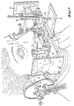
- FIG. 1 shows the individual parts of the device according to the invention, which are essentially an articulator lower part 1, an articulator upper part 2 which can be pivotally mounted thereon, and a pantograph part 3, consisting of a lower jaw registration sheet 4 and one Upper jaw registration sheet 5.
- Each of the parts 1 and 2 carries a denture model, namely the lower articulator part 1, the lower jaw teeth model 6 and the upper articulator part, the upper jaw teeth model 7.
- the lower jaw registration sheet 4 carries the lower jaw teeth impression 8
- the upper jaw -Registration sheet 5 carries the maxillary teeth impression 9.
- the two models 6 and 7 are connected in the manner described in CH-PS 604 675 with the associated articulator parts, that is, the maxillary teeth model 7 is via compensation means 31, which essentially consist of a compensation plate 32, a centering ring 33 with three centering screws 34 in a 120 ° arrangement and a fixing screw 35, connected to the upper part 2 of the articulator.
- the upper jaw teeth model 7 can thus be positioned on the articulator upper part 2 in a three-dimensionally reproducible manner, as is necessary for an exact reproduction of the registered occlusion position on the patient.
- the lower jaw teeth model 6, in contrast, is plastered directly onto a base plate 36, which is fastened with a screw, not shown the articulator lower part 1 is connectable.
- the prints 8 and 9 are advantageously by means of intraoral fixation spoons 17 according to the int.
- Model DM / 001 188 attached to the corresponding registration sheets.
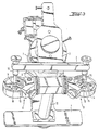
- the lower part 1 of the articulator has a single central support 10 (FIG. 3), so that the view of the bit models 6 and 7 mounted in the articulator is also diagonally free and all teeth are freely accessible.
- the two blocks 11 and 12 (FIG. 3) of the guide elements are mounted on a common central axis 30 on the intercondylar axis A in positions fixed relative to one another and can be rotated about the intercondylar axis A.
- Each block 11, 12 is laterally displaceable on the intercondylar axis A and each has a screwable cylindrical pin 13, by means of which the condyle balls 14 (FIG. 3) can be fixed.
- the lower part 1 of the articulator has a known, adjustable support 28 for a front support pin 29.
- the upper part of the articulator 2 can receive the said support pin 29 in a displaceable and lockable manner and the arms 15 with the condyle balls 14 seated at their lower ends are equipped with auxiliary rings 16. which can be pushed over the condyle balls 14 in order to enlarge their effective diameter planes. It can be used to simulate retrusion movements for diagnosing occlusal transversal and retral displacements without losing the mounting position of models 6 and 7.
- the arms 15 are fixed, i. H. cannot be moved laterally.
- the lower jaw registration sheet 4 has tips 24 that can be placed on the intercondylar axis A of the lower jaw, and the lower jaw teeth impression 8 is connected to it by means of a prescribed fixing spoon 17.
- This fixation spoon 17 is in turn equipped with a positionable McGrane pin.
- the front registration plate 18 is, like the two lateral registration plates 19 and 20, made of plexiglass and removable. All three registration plates 18 to 20 can be positioned reproducibly.
- the lateral registration plates 19 and 20 are dimensioned and arranged such that the entire opening movements of the lower jaw can be completely recorded in three dimensions.
- the upper jaw registration sheet 5 carries the upper jaw teeth impression 9 on a removable fixation spoon 17 of the aforementioned type, which, however, does not have a McGrane pin.
- Auxiliary registration plates 22 and 23 can be mounted thereon by means of clampable columns 21, such. that they can work with the tips 24.
- These additional saggital-vertical auxiliary registration plates improve the diagnostic possibilities by e.g. B. can bring pathological changes in the condylar movements or malfunctions of the cartilage disc directly to the display. And this fulfills the prerequisite for deriving the so-called «therapeutic centric.
- the new design of the lower part 1 of the articulator has very significant advantages over all known articulators, since the only central support 10 enables all teeth of the models 6, 7 to be freely accessed.
- the fixed connection of the blocks 11 and 12 relating to the intercondylar axis A by means of the axis 30 as a support for the upper part 2 of the articulator, connected to the cylindrical pins 13, by means of which the condyle balls 14 can be firmly positioned on the guide elements, for the first time enables completely fold the upper part of the articulator 2 from the lower part 1 without losing its position relative to it.
- a lateral bite positioning unit which can be displaced centrally around blocks 11 and 12.
- a cylindrical pin 13 which can act on the condyle balls 14, each side bite position of the models 6 and 7, or each medio and laterotrusion movement, can also be recorded in the articulator.
- the new device offers the possibility of a direct and simultaneous combination of axis determination and recording of the condylar movements in one work step. It also makes it possible. by means of the auxiliary registration plates 22, 23 and the tips 24 on the intercondylar axis A to register the precise movements of the temporomandibular joint and a pathological one To detect TMJ crack correctly and in time.
- the common axis 30 of the two blocks 11 and 12 is mounted on ball bearings and can be locked as desired either in a defined position relative to the fixed central support 10, or is held so that it can rotate around its longitudinal axis, the intercondylar axis A, without rotation, the relative positioning of the two Blocks 11 and 12 always remain fixed and reproducible to each other, and the articulator upper part 2, thanks to the screwable cylinder pins 13, can also be positioned firmly and reproducibly in relation to blocks 11 and 12, the articulator 1, 2 can be used as a three-dimensional, freely movable replica of a patient's dentition as well as a pure hinge joint without having to change any settings and measured values.
- all registration plates can be provided with positioning and fastening elements for the reproducible positioning of non-self-adhesive recording papers. These can be, among other things, adjustable clamping rails and positioning pins. Furthermore, the registration plates can be equipped with transparent cover sheets, which prevent the marks on the recording papers from being reproduced unintentionally when the curves are reproduced.
- the registration plates can end in miniature spheres or can be replaced by self-writing pens if non-pressure-sensitive recording papers are to be used.
- the same can be provided with a hydrophobic permanent covering.
- the front support pin 29 can be fitted in a clamping manner in a guide slot or can be mounted on a displaceable slide in such a way that it can be rotated and tilted in any forward or backward bite position. This makes it easy to understand the immediate side shift at the back.
- An adjustment scale can be provided to make the respective position of the pin determinable.
Abstract
Description
Die vorliegende Erfindung betrifft eine Vorrichtung für die Aufzeichnung der Kondylenbewegungen eines Patienten und deren nachträglicher exakter Simulation unter Einbezug von Ober- und Unterkieferzähne-Modellen zwecks Bestimmung der notwendigen Korrekturen der Kauflächen für die Erlangung der idealen Okklusion, gemäss dem Oberbegriff des Patentanspruchs 1.The present invention relates to a device for recording the condylar movements of a patient and their subsequent exact simulation, including upper and lower jaw models, for the purpose of determining the necessary corrections to the occlusal surfaces for achieving the ideal occlusion, according to the preamble of
In der Zahnheilkunde ist, z. B. aus dem 1961 im Verlag Mosbey & Co. erschienenen Buch « Modern Gnathological Concepts " von Victor 0. Lucia, bereits eine Mehrzahl von Geräten und Vorrichtungen bekannt, die der Aufzeichnung und Nachbildung der habituellen Okklusion eines Patienten dienen, und zum Zwecke haben, Funktions- oder Okklusionsstörungen des Patienten durch Korrektur der Kauflächenprofile der Zähne an Ober- und Unterkiefer zu korrigieren. Der Praktiker weiss aber, dass all diese Geräte und Vorrichtungen entweder sehr kompliziert zu bedienen sind und/oder Ergebnisse bringen, deren praktische Auswertung sehr aufwendig ist. Zudem lassen sie in der Regel keine nachträgliche Korrektur der Zuordnung der Kauflächen von Ober- und Unterkieferzähnen im Gerät selbst zu, um z. B. Montage- oder Gipsexpansions-Fehler auszugleichen. Ferner werden oft für die Registrierung der Kondylenbewegungen am Patienten und deren Nachbildung separate Geräte verwendet, was die Reproduzierbarkeit der Messungen und Bewegungen stark in Frage stellt, wenn nicht verunmöglicht.In dentistry, e.g. B. from the book "Modern Gnathological Concepts" by Victor 0. Lucia, published by Mosbey & Co. in 1961, a number of devices and devices are already known which serve to record and simulate the habitual occlusion of a patient and have the purpose, Correcting functional or occlusal disorders of the patient by correcting the occlusal profile of the teeth on the upper and lower jaw, but the practitioner knows that all of these devices and devices are either very complicated to use and / or produce results whose practical evaluation is very complex. In addition, they usually do not allow any subsequent correction of the assignment of the occlusal surfaces of the upper and lower jaw teeth in the device itself, for example to compensate for assembly or gypsum expansion errors, and are often separate for the registration of the condylar movements on the patient and their replication Equipment used, which greatly affects the reproducibility of measurements and movements in Fr age poses if not impossible.
Diese Nachteile hat der Artikulator gemäss der CH-PS 437 629 (US-PS 3,552,020) sowie dessen erste Weiterentwicklung gemäss der CH-PS 604 675 (US-PS 4,185,387) in weitem Masse beseitigt. Es handelt sich bei diesem Gerät erstmals um ein solches, das die räumliche Lagebeziehung des Unterkiefers zum Oberkiefer und die Bewegungen des Unterkiefers anhand einer geeigneten Grenzbewegungsaufzeichnung einzustellen gestattet, was anhand eines zugehörigen Pantografen, der auf die mit dem Artikulator verbundenen Gebissmodelle eines Patienten aufsetzbar ist, in Verbindung mit einem justierbaren Kontrollsockel geschieht. Mit diesem bekannten Gerät lässt sich die ganze Problematik um das « Zentrische Registrat » erstmals in befriedigender Art und Weise lösen.The articulator according to CH-PS 437 629 (US-PS 3,552,020) and its first further development according to CH-PS 604 675 (US-PS 4,185,387) have largely eliminated these disadvantages. For the first time, this device is one that allows the spatial positional relationship of the lower jaw to the upper jaw and the movements of the lower jaw to be adjusted on the basis of a suitable limit motion recording, which can be done using an associated pantograph that can be placed on the dentition models of a patient connected to the articulator. in conjunction with an adjustable control base. With this well-known device, the whole problem of the "central registration" can be solved for the first time in a satisfactory manner.
Ungelöst ist auch in diesem bekannten Artikulator allerdings das Problem der Fixation der Gebissmodelle in der habituellen Okklusionsstellung und der direkte Vergleich von registrierter und habitueller Okklusion auf dem Artikulator, ohne umgipsen der Gebissmodelle. Das damit zusammenhängende Problem der freien Zugänglichkeit zu den Gebissmodellen zwecks Bearbeitung der Kauflächen ist ebenfalls ungelöset.In this known articulator, however, the problem of the fixation of the dentition models in the habitual occlusion position and the direct comparison of registered and habitual occlusion on the articulator, without plastering of the denture models, is also unsolved. The associated problem of free access to the denture models for processing the occlusal surfaces has also not been solved.
Aufgabe der vorliegenden Erfindung ist es, eine verbesserte Vorrichtung für die Aufzeichnung der Kondylenbewegungen eines Patienten an ihm selber und deren nachträglicher exakter Simulation im Artikulator anhand von mit dem Artikulator verbundenen Gebissmodellen zu schaffen, die einerseits gegenüber dem aus der CH-PS 604 675 bekannten Gerät weitergehende diagnostische Möglichkeiten bietet und die zudem eine vereinfachte Manipulation ermöglicht und insbesondere das Zurückklappen des Artikulator-Oberteils in beiden Okklusionsstellungen, der registrierten und der habituellen, gestattet, ohne die Modelle umgipsen oder sonstwie ummontieren zu müssen.The object of the present invention is to provide an improved device for recording the condylar movements of a patient on him himself and their subsequent exact simulation in the articulator on the basis of denture models connected to the articulator, which on the one hand compared to the device known from CH-PS 604 675 offers further diagnostic possibilities and which also enables simplified manipulation and, in particular, allows the articulator upper part to be folded back in both occlusion positions, the registered and the habitual, without having to plaster or otherwise reassemble the models.
Erfindungsgemäss wird diese Aufgabe durch die verbesserte Vorrichtung gelöst, wie sie im Patentanspruch 1 definiert ist.According to the invention, this object is achieved by the improved device as defined in
Im Folgenden ist eine vorteilhafte Ausführungsvariante der erfindungsgemässen Vorrichtung sowie deren Verwendung anhand der Zeichnungen beschrieben. In letzteren zeigt
Figur 1 die Vorrichtung in der Zusammenstellung, wie sie für die Uebertragung der am Patienten aufgezeichneten Unterkieferbewegungen anhand von Gebissmodellen der Ober-und Unterkieferzähne des Patienten verwendet wird,Figur 2 den Pantograf-Teil der Vorrichtung im Einsatz beim Registrieren der habituellen Okklusion an einer Patienten, und- Figur 3 den Artikulator-Teil der Vorrichtung von hinten oben, mit Blick auf die Montage der Blocks der Leitelemente, mittels welchen das Artikulator-Oberteil auf dessen Unterteil gelagert ist.
- FIG. 1 shows the device as it is used for the transmission of the lower jaw movements recorded on the patient using dentition models of the patient's upper and lower teeth,
- Figure 2 shows the pantograph part of the device in use when registering the habitual occlusion on a patient, and
- Figure 3 shows the articulator part of the device from above, with a view of the assembly of the blocks of the guide elements, by means of which the upper part of the articulator is mounted on its lower part.
In Fig. 1 erkennt man die einzelnen Teile der erfindungsgemässen Vorrichtung, bei denen es sich im wesentlichen um ein Artikulator-Unterteil 1, ein schwenkbar darauf montierbares Artikulator-Oberteil 2 sowie ein Pantograf-Teil 3, bestehend aus einem Unterkiefer-Registrierbogen 4 und einem Oberkiefer-Registrierbogen 5, handelt. Dabei trägt jedes der Teile 1 und 2 ein Gebissmodell, und zwar das Artikulator-Unterteil 1 das Unterkieferzähne-Modell 6 und das Artikulator-Oberteil das Oberkieferzähne-Modell 7. Ferner trägt der Unterkiefer-Registrierbogen 4 den Unterkieferzähne-Abdruck 8, wogegen der Oberkiefer-Registrierbogen 5 den Oberkieferzähne-Abdruck 9 trägt. Vorteilhafterweise sind dabei die beiden Modelle 6 und 7 in der in der CH-PS 604 675 beschriebenen Art mit den zugehörigen Artikulator-Teilen verbunden, d. h., das Oberkieferzähne- Modell 7 ist über Kompensationsmittel 31, die im wesentlichen aus einer Kompensationsplatte 32, einem Zentrierring 33 mit drei Zentrierschrauben 34 in 120°-Anordnung und einer Fixationsschraube 35 bestehen, mit dem Artikulator-Oberteil 2 verbunden. Damit kann das Oberkieferzähne-Modell 7 auf dem Artikulator-Oberteil 2 dreidimensional reproduzierbar positioniert werden, wie das für eine exakte Reproduktion der registrierten Okklusionsstellung am Patienten notwendig ist. , Das Unterkieferzähne-Modell 6 wird demgegenüber direkt auf eine Grundplatte 36 gegipst, die mittels einer nicht dargestellten Schraube mit dem Artikulator-Unterteil 1 verbindbar ist.1 shows the individual parts of the device according to the invention, which are essentially an articulator
Die Abdrücke 8 und 9 ihrerseits sind vorteilhafterweise mittels intraoralen Fixierungslöffeln 17 gemäss dem Int. Modell DM/001 188 auf den entsprechenden Registrierbögen befestigt.The
Gegenüber den vorerwähnten bekannten Ausführungen von Artikulatoren gemäss CH-PS 437 629 und CH-PS 604 675 unterscheiden sich die einzelnen Teile der neuen Vorrichtung im wesentlichen durch die nachfolgend aufgeführten Verbesserungen.Compared to the aforementioned known designs of articulators according to CH-PS 437 629 and CH-PS 604 675, the individual parts of the new device differ essentially in the improvements listed below.
Das Artikulator-Unterteil 1 weist eine einzige Mittelstütze 10 (Fig. 3) auf, so dass die Sicht auf die im Artikulator montierten Gebissmodelle 6 und 7 auch diagonal frei ist und alle Zähne frei zugänglich sind. Die beiden Blocks 11 und 12 (Fig. 3) der Leitelemente sind auf einer gemeinsamen zentralen Achse 30 auf der Interkondylarachse A in relativ zueinander fixierten Lagen montiert und um die Interkondylarachse A drehbar. Jeder Block 11, 12 ist auf der Interkondylarachse A lateral verschiebbar und weist je einen schraubbaren Zylinderstift 13 auf, mittels welchem die Kondylenkugeln 14 (Fig. 3) fixiert werden können. In seinem zentralen vorderen Bereich weist das Artikulator-Unterteil 1 eine an sich bekannte, verstellbare Abstützung 28 für einen vorderen Stützstift 29 auf.The
Das Artikulator-Oberteil 2 kann in seinem vorderen Bereich den besagten Stützstift 29 verschieb-und feststellbar aufnehmen und die Arme 15 mit den an ihren unteren Enden sitzenden Kondylenkugeln 14 sind mittels Hilfsringen 16 ausgerüstet. die sich über die Kondylenkugeln 14 schieben lassen, um deren wirksame Durchmesserebenen zu vergrössern. Damit lassen sich Retrusionsbewegungen zur Diagnose okklusionsbedingter Transversal- und Retralverlagerungen simulieren, ohne dass die Montageposition der Modelle 6 und 7 verloren geht. Die Arme 15 sind fest, d. h. seitlich nicht versetzbar.The upper part of the
Der Unterkiefer-Registrierbogen 4 weist auf die Interkondylarachse A des Unterkiefers legbare Spitzen 24 auf und der Unterkieferzähne-Abdruck 8 ist mittels einem vorbeschriebenen Fixierungslöffel 17 mit ihm verbunden. Dieser Fixierungslöffel 17 ist seinerseits mit einem positionierbaren McGrane'schen Stift ausgerüstet. Die vordere Registrierplatte 18 ist, genau so wie die beiden seitlichen Registrierplatten 19 und 20, aus Plexiglas und abnehmbar. Alle drei Registrierplatten 18 bis 20 können reproduzierbar positioniert werden. Die seitlichen Registrierplatten 19 und 20 sind so bemessen und angeordnet, dass die ganzen Oeffnungsbewegungen des Unterkiefers dreidimensional vollständig erfasst werden können.The lower jaw registration sheet 4 has
Der Oberkiefer-Registrierbogen 5 trägt den Oberkieferzähne-Abdruck 9 auf einem abnehmbaren Fixierungslöffel 17 der vorerwähnten Art, der jedoch keinen McGrane'schen Stift aufweist. Mittels festklemmbaren Säulen 21 sind Hilfsregistrierplatten 22 und 23 darauf montierbar, derart. dass sie mit den Spitzen 24 zusammenwirken können. Diese zusätzlichen saggital-vertikalen Hilfsregistrierplatten verbessern die diagnostischen Möglichkeiten, indem sie z. B. pathologische Veränderungen der Kondylenbewegungen oder Fehlfunktionen der Knorpelscheibe direkt zur Darstellung bringen können. Und damit ist die Voraussetzung zur Ableitung der sogenannten « therapeutischen Zentrik ertüllt.The upper
Durch die sich durch die beschriebene Anordnung der einzelnen Elemente ergebende Führung des McGrane'schen Stiftes des unteren Fixierungslöffels 17 auf dem als Führungsplatte dienenden oberen Fixierungslöffel 17 wird erreicht. dass auf den Registrierebenen bei der Registrierung aller Artikulationsbewegungen drei eindeutige Kreuzungspunkte für die Zentrik entstehen.The result of guiding the McGrane pin of the
Der Fachmann erkennt, dass mit all diesen konstruktiven Verbesserungen die bekannten Ausführungsformen von Artikulatoren in einigen ganz wesentlichen anwendungstechnischen Punkten verbessert werden. Insbesondere werden dadurch diesen bekannten Geräten noch anhaftende Nachteile überwunden und sogar neue diagnostische Möglichkeiten geschaffen.Those skilled in the art will recognize that with all of these design improvements, the known embodiments of articulators are improved in some very important application-related points. In particular, this known devices still overcome disadvantages and even new diagnostic possibilities are created.
So bildet insbesondere die neue Ausgestaltung des Artikulator-Unterteils 1 gegenüber allen bekannten Artikulatoren ganz wesentliche Vorteile, ermöglicht es doch die einzige Mittelstütze 10, an alle Zähne der Modelle 6, 7 frei heranzukommen.In particular, the new design of the
Zudem schafft die auf die Interkondylarachse A bezogene feste Verbindung der Blocks 11 und 12 mittels der Achse 30 als Auflage für das Artikulator-Oberteil 2, verbunden mit den Zylinderstiften 13, mittels welchen die Kondylenkugeln 14 an den Leitelementen fest positionierbar sind, erstmals die Möglichkeit, das Artikulator-Oberteil 2 völlig vom Unterteil 1 abzuklappen, ohne seine relative Lage zu diesem zu verlieren.In addition, the fixed connection of the
Ferner ist es dank der Möglichkeit der progressiven Verschiebung eines jeden Blocks 11, 12 auf der Interkondylarachse A lateral mittels eines sogenannten « immediate side-shift und der Verwendung der Hilfsringe 16 erstmals möglich, jede gewünschte therapeutische Vorbiss-, Rückbiss- und Seitenbissposition der Modelle 6 und 7 ohne Verstellung des Artikulators zu realisieren.Furthermore, thanks to the possibility of the progressive displacement of each
Durch die Verwendung verschiedener Kurvenscheiben-Einsätze als Auflagen für die Kondylenkugeln 14 in den Blöcken 11 und 12 können diese Möglichkeiten zusätzlich erweitert werden.By using different cam disk inserts as supports for the
Mittels je einer zentrisch rund um die Blocks 11 und 12 verschiebbar angeordneten Seitbiss-Positionierungseinheit. im wesentlichen bestehend aus einem Zylinderstift 13, der auf die Kondylenkugeln 14 einwirken kann, kann auch jede Seitbissposition der Modelle 6 und 7, respektive jede Medio- und Laterotrusionsbewegung im Artikulator festgehalten werden.By means of a lateral bite positioning unit which can be displaced centrally around
Die neue Vorrichtung bietet erstmals die Möglichkeit der direkten und gleichzeitigen Kombination von Achsenbestimmung und Aufzeichnung der Kondylenbewegungen in einem Arbeitsgang. Sie ermöglicht es auch. mittels der Hilfsregistrierplatten 22, 23 und den Spitzen 24, auf der Interkondylarachse A die genauen Kiefergelenkbewegungen zu registrieren und ein krankhaftes Kiefergelenkknacken örtlich und zeitlich einwandfrei zu erfassen.For the first time, the new device offers the possibility of a direct and simultaneous combination of axis determination and recording of the condylar movements in one work step. It also makes it possible. by means of the
Dank der räumlich genau reproduzierbaren Positionierung aller Registrierplatten (18, 19, 20 und 22, 23) und der Abdrücke 8 und 9 des Pantograf-Teils 3 sowie der Gebissmodelle 6 und 7 auf dem Artikulator, und der Tatsache, dass dieser jederzeit ohne Notwendigkeit der Verstellung irgend einer Einstellung sowohl an ihm selber als auch am Artikulator 1, 2 von diesem zur Kontrolle der Arbeit wieder in den Mund des Patienten einsetzbar ist, ist es möglich, jederzeit sowohl die habituelle als auch die ideale Okklusion eines Patienten zu rekonstruieren, selbst wenn sämtliche Teile demontiert worden waren. Zudem kann das Artikulator-Oberteil 2 in beiden Okklusionsstellungen der Kondylenkugeln 14 zurückgeklappt werden. Eine Uebertragung der Messwerte und Ergebnisse von einem Gerät auf das andere ist dadurch erstmals problemlos möglich. Die erfindungsgemässe Vorrichtung ermöglicht es aber auch, die Messungen und Artikulationsbewegungen computergerecht zu erfassen und auszuwerten, indem sie durch beliebige bekannte Verfahren in elektrische Signale, umgewandelt werden.Thanks to the spatially precisely reproducible positioning of all registration plates (18, 19, 20 and 22, 23) and the
Indem die gemeinsame Achse 30 der beiden Blocks 11 und 12 auf Kugellagern gelagert wird und nach Belieben entweder in einer definierten Lage gegenüber der festen Mittelstütze 10 feststellbar, oder um ihre Längsachse, die Interkondylarachse A, speilfrei drehbar gehalten wird, wobei die relative Positionierung der beiden Blocks 11 und 12 zueinander immer fest und reproduzierbar bleibt, und das Artikulator-Oberteil 2 dank der schraubbaren Zylinderstifte 13 gegenüber den Blocks 11 und 12 ebenfalls fest und reproduzierbar positionierbar ist, lässt sich der Artikulator 1, 2 sowohl als dreidimensional frei bewegliche Nachbildung eines Patientengebisses als auch als reines Scharniergelenk einsetzen, ohne dass dadurch irgendwelche Einstellungen und Messwerte verändert werden müssten. Dadurch wird die Arbeit des Einschleifens korrekter Kauflächenreliefs an den Gebissmodellen 6 und 7 wesentlich erleichtert, denn durch einfaches Festziehen der Zylinderstifte 13 und das Freigeben der Achse 30 auf der Interkondylarachse A lässt sich das Artikulator-Oberteil 2 in eine völlig stabile Horizontallage parallel zum Unterteil 1 zurückklappen, ohne sich auf den eingesetzten und festgestellten frontalen Stützstift 29 rückwärts abstützen zu müssen. Nun kann problemlos sowohl am Unterkiefer- als auch am Oberkieferzähne-Modell 6, resp. 7 gearbeitet werden, worauf durch simples Zurückklappen des Oberteils 2 und Blockieren der Achse 30 sowie Lösen der Zylinderstifte 13 die ursprüngliche räumliche Lagebeziehnung zwischen Unter- und Oberkieferzähne-Modell 6 und 7 wieder hergestellt ist.In that the
Beim Gebrauch der neuen Vorrichtung, die zwangsläufig aus dem Artikulatorteil 1, 2 und dem Pantograf-Teil 3 besteht und in Verbindung mit den auf dem Artikulator montierten Gebissmodellen 6, 7 und den mit dem Pantografen verbundenen Abdrücken 8, 9 einzusetzen ist, wird der Fachmann feststellen, welchen Stellenwert die vorerwähnten Verbesserungen aufweisen und wie stark sie ihm die Arbeit erleichtern.When using the new device, which inevitably consists of the
Die hiervor beschriebene verbesserte erfindungsgemässe Vorrichtung für die Aufzeichnung der Kondylenbewegungen eines Patienten und deren nachträglicher exakter Simulation kann bei Bedarf in Einzelheiten verändert und/oder noch weiter verbessert werden. So können beispielsweise sämtliche Registrierplatten mit Positionierungs- und Befestigungselementen für das reproduzierbare Positionieren nicht selbst klebender Aufzeichnungspapiere versehen sein. Dies können unter anderem verstellbare Klemmschienen und Positionierungsstifte sein. Ferner können die Registrierplatten mit transparenten Deckblättern bestückt werden, die verhindern, dass bei der Reproduktion der sich auf den Aufzeichnungspapieren befindlichen Kurven ungewollt neue Markierungen ergeben.The improved device according to the invention described above for recording the condylar movements of a patient and their subsequent exact simulation can, if necessary, be changed in details and / or further improved. For example, all registration plates can be provided with positioning and fastening elements for the reproducible positioning of non-self-adhesive recording papers. These can be, among other things, adjustable clamping rails and positioning pins. Furthermore, the registration plates can be equipped with transparent cover sheets, which prevent the marks on the recording papers from being reproduced unintentionally when the curves are reproduced.
Weiter können die Registrierplatten in Miniaturkugeln enden oder durch selbstschreibende Stifte ersetzt werden, wenn nicht druckempfindliche Aufzeichnungspapiere verwendet werden sollen. Um das Loslösen der Gipssockel vom Artikulator zu erleichern, kann derselbe mit einem hydrophoben Dauerbelag versehen werden.Furthermore, the registration plates can end in miniature spheres or can be replaced by self-writing pens if non-pressure-sensitive recording papers are to be used. In order to facilitate the detachment of the plaster base from the articulator, the same can be provided with a hydrophobic permanent covering.
Der vordere Stützstift 29 kann in einem Führungsschlitz klemmend eingepasst oder auf einem verschiebbaren Schlitten so montiert sein, dass er in jeder Vor- oder Rückbisslage drehend und kippend arretierbar ist. Damit kann hinten der « immediate side-shift sehr schön nachvollzogen werden. Um die jeweilige Stellung des Stiftes bestimmbar zu gestalten, kann eine Einstellskala vorgesehen werden.The
Claims (3)
Priority Applications (1)
| Application Number | Priority Date | Filing Date | Title |
|---|---|---|---|
| AT84901946T ATE28558T1 (en) | 1983-05-10 | 1984-05-10 | DEVICE FOR RECORDING THE CONDYLAR MOVEMENTS OF A PATIENT AND THEIR SIMULATION USING DENTISTRY MODELS. |
Applications Claiming Priority (2)
| Application Number | Priority Date | Filing Date | Title |
|---|---|---|---|
| CH2549/83 | 1983-05-10 | ||
| CH2549/83A CH665116A5 (en) | 1983-05-10 | 1983-05-10 | DEVICE FOR THE RECORDING OF A PATIENT'S JAW ENCLOSURE AND ITS REPRODUCTION USING BIT MODELS. |
Publications (2)
| Publication Number | Publication Date |
|---|---|
| EP0143813A1 EP0143813A1 (en) | 1985-06-12 |
| EP0143813B1 true EP0143813B1 (en) | 1987-07-29 |
Family
ID=4236291
Family Applications (2)
| Application Number | Title | Priority Date | Filing Date |
|---|---|---|---|
| EP84901946A Expired EP0143813B1 (en) | 1983-05-10 | 1984-05-10 | Device for the representation on condylar motions of a patient and their simulation |
| EP84810228A Pending EP0128117A1 (en) | 1983-05-10 | 1984-05-10 | Device for recording the condyle |
Family Applications After (1)
| Application Number | Title | Priority Date | Filing Date |
|---|---|---|---|
| EP84810228A Pending EP0128117A1 (en) | 1983-05-10 | 1984-05-10 | Device for recording the condyle |
Country Status (7)
| Country | Link |
|---|---|
| US (1) | US4773854A (en) |
| EP (2) | EP0143813B1 (en) |
| JP (1) | JPS60501693A (en) |
| AT (1) | ATE28558T1 (en) |
| CH (1) | CH665116A5 (en) |
| DE (1) | DE3465012D1 (en) |
| WO (1) | WO1984004448A1 (en) |
Cited By (1)
| Publication number | Priority date | Publication date | Assignee | Title |
|---|---|---|---|---|
| DE4024124A1 (en) * | 1990-07-30 | 1992-02-20 | Hanns Joachim Feyen | Appts. for measuring lower jaw movements - works in relation to skull with printer displaceable transversally on recording sheet |
Families Citing this family (16)
| Publication number | Priority date | Publication date | Assignee | Title |
|---|---|---|---|---|
| AT385410B (en) * | 1985-02-12 | 1988-03-25 | Lisec Bernhard | DEVICE FOR DETERMINING ORAL AND PATIENT DETERMINATION OF THE HINGE AXIS AND THE LINEAR LIMITATION OF THE LOWER JAW |
| US4681539A (en) * | 1985-09-06 | 1987-07-21 | Knap Florian J | Dental articulator and method |
| JP2955841B2 (en) * | 1996-07-10 | 1999-10-04 | 三金工業株式会社 | Occlusal viewing device |
| US6152731A (en) * | 1997-09-22 | 2000-11-28 | 3M Innovative Properties Company | Methods for use in dental articulation |
| US9084653B2 (en) | 1998-01-14 | 2015-07-21 | Cadent, Ltd. | Methods for use in dental articulation |
| US8021149B2 (en) * | 2007-04-17 | 2011-09-20 | Gnath Tech Dental Systems, Llc | Apparatus and method for replicating mandibular movement |
| US8382686B2 (en) * | 2007-04-17 | 2013-02-26 | Gnath Tech Dental Systems, Llc | Apparatus and method for recording mandibular movement |
| FR2974292B1 (en) * | 2011-04-19 | 2015-08-07 | Tali | APPARATUS AND METHOD FOR PLACING ROD PIVOTS FOR DENTAL ORTHESES |
| US20140238414A1 (en) | 2013-02-22 | 2014-08-28 | Kelly Lucas | AGP night guard - for a bruxism patient with or without a severe malocclusion |
| US9730768B2 (en) | 2013-02-22 | 2017-08-15 | Kelly Lucas | CAD-CAM AGP splint—a method of automatically producing or reproducing a customized AGP (anterior guidance package) equipped splint for a patient with/without a severe malocclusion via one time dentist visit |
| US9526590B2 (en) | 2013-02-22 | 2016-12-27 | Kelly Lucas | AGP night guard—for a bruxism patient with or without a severe malocclusion |
| BG66738B1 (en) * | 2013-03-22 | 2018-09-28 | Димитров Филчев Андон | Method for articulator adjustment and gnathological instruments for work under this method |
| US9655692B2 (en) | 2013-11-19 | 2017-05-23 | Kelly Wade Lucas | Pre-fabricated anterior guidance package kit for patients having bruxism/clenching habit with or without various malocclusions-II |
| US10610404B2 (en) | 2015-06-24 | 2020-04-07 | Kelly Lucas | Systems and methods for producing anterior guidance package (AGP) equipped splint |
| US10350038B1 (en) * | 2017-07-31 | 2019-07-16 | Austin H. Sampson | Dental articulator system and apparatus |
| US11389123B2 (en) | 2018-06-20 | 2022-07-19 | Lourens Russel Du Preez | Method for determining treatment of orthopaedic imbalances, and apparatus therefor |
Family Cites Families (6)
| Publication number | Priority date | Publication date | Assignee | Title |
|---|---|---|---|---|
| US2070025A (en) * | 1934-06-07 | 1937-02-09 | George P Phillips | Dental instrument |
| US3431649A (en) * | 1964-02-28 | 1969-03-11 | Niles F Guichet | Dental face bow |
| NL6505462A (en) * | 1965-04-29 | 1966-10-31 | ||
| DE2551189C2 (en) * | 1975-03-15 | 1982-02-11 | Mack, Heinz, 8000 München | Mounting plate for dental articulators |
| CH604675A5 (en) * | 1976-10-21 | 1978-09-15 | Weber Roland | |
| US4290754A (en) * | 1980-02-12 | 1981-09-22 | Ab Dentatus | Articulator for use in the making of dentures or parts thereof |
-
1983
- 1983-05-10 CH CH2549/83A patent/CH665116A5/en not_active IP Right Cessation
-
1984
- 1984-05-10 WO PCT/CH1984/000071 patent/WO1984004448A1/en active IP Right Grant
- 1984-05-10 JP JP84501874A patent/JPS60501693A/en active Pending
- 1984-05-10 DE DE8484901946T patent/DE3465012D1/en not_active Expired
- 1984-05-10 AT AT84901946T patent/ATE28558T1/en not_active IP Right Cessation
- 1984-05-10 EP EP84901946A patent/EP0143813B1/en not_active Expired
- 1984-05-10 EP EP84810228A patent/EP0128117A1/en active Pending
-
1985
- 1985-01-10 US US06/690,247 patent/US4773854A/en not_active Expired - Fee Related
Cited By (1)
| Publication number | Priority date | Publication date | Assignee | Title |
|---|---|---|---|---|
| DE4024124A1 (en) * | 1990-07-30 | 1992-02-20 | Hanns Joachim Feyen | Appts. for measuring lower jaw movements - works in relation to skull with printer displaceable transversally on recording sheet |
Also Published As
| Publication number | Publication date |
|---|---|
| US4773854A (en) | 1988-09-27 |
| EP0128117A1 (en) | 1984-12-12 |
| CH665116A5 (en) | 1988-04-29 |
| JPS60501693A (en) | 1985-10-11 |
| ATE28558T1 (en) | 1987-08-15 |
| DE3465012D1 (en) | 1987-09-03 |
| WO1984004448A1 (en) | 1984-11-22 |
| EP0143813A1 (en) | 1985-06-12 |
Similar Documents
| Publication | Publication Date | Title |
|---|---|---|
| EP0143813B1 (en) | Device for the representation on condylar motions of a patient and their simulation | |
| DE10154994B4 (en) | Dentofacial analysis device | |
| WO1992002192A2 (en) | Dental articulator and face-bow with bite-fork column | |
| DE69918484T2 (en) | Device for scanning the centric relation of the mandible | |
| DE69738125T2 (en) | DEVICE AND METHOD FOR POSITIONING A PINK TOOTH BODY MODEL IN AN ARTICULATOR | |
| DE102013004102A1 (en) | Process for the production of dentures and articulator for carrying out the method | |
| DE3002174C2 (en) | Registration device for intraoral recording of lower jaw movements | |
| DE2742674A1 (en) | ARTICULATOR FOR CHECKING AND CORRECTING THE MOUTH PROFILE OF THE TEETH | |
| DE69822343T2 (en) | OCCLUSION ARRANGEMENT WITH COMPLETE REPRODUCIBILITY | |
| DE3608442A1 (en) | ARTICULATOR | |
| DE3313198C2 (en) | Device for plastering jaw models in the manufacture of dentures | |
| DE4018755C1 (en) | ||
| EP0470537A1 (en) | Dental articulator | |
| DE3314136C2 (en) | ||
| DE2931271A1 (en) | DEVICE FOR THE MANUFACTURE OF DENTAL PROSTHESES FOR SIMULATING THE RELATIVE MOVEMENTS WHEN CHEWING | |
| AT406334B (en) | DENTAL ARTICULATOR OR ADDITIONAL DEVICE FOR A DENTAL ARTICULATOR | |
| DE102010018825B4 (en) | Device and method for positioning a real lower jaw model and an upper jaw model for producing a splint or prosthesis for correcting the condylar position of a temporomandibular joint | |
| EP0191755A2 (en) | Device for the remote determination of the jaw axes and of the linear liniting movement of the lower jaw | |
| DE102008044886B4 (en) | dental articulator | |
| DE19945098A1 (en) | Quick transfer sheet | |
| DE19928268B4 (en) | Device for the simulation of temporomandibular joint positions | |
| DE202016000353U1 (en) | Device for spatial positioning of the upper jaw taking into account individual parameters and occlusion fork with determination of the position in the room | |
| DE4219795A1 (en) | Precise location for dental articulation hinge axis - obtains adjusting block by arbitrary rapid transfer arch via impression plate. | |
| Gibbs et al. | A new articulator emphasizing centric occlusion and the anterior determinants | |
| DE1491062A1 (en) | Dental articulator and method for its use |
Legal Events
| Date | Code | Title | Description |
|---|---|---|---|
| PUAI | Public reference made under article 153(3) epc to a published international application that has entered the european phase |
Free format text: ORIGINAL CODE: 0009012 |
|
| 17P | Request for examination filed |
Effective date: 19841217 |
|
| AK | Designated contracting states |
Designated state(s): AT BE CH DE FR GB LI LU NL SE |
|
| RBV | Designated contracting states (corrected) |
Designated state(s): AT BE CH DE FR GB IT LI LU NL SE |
|
| XX | Miscellaneous (additional remarks) |
Free format text: VERBUNDEN MIT 84810228.1/0128117 (EUROPAEISCHE ANMELDENUMMER/VEROEFFENTLICHUNGSNUMMER) DURCH ENTSCHEIDUNG VOM 30.10.85. |
|
| GRAA | (expected) grant |
Free format text: ORIGINAL CODE: 0009210 |
|
| ITF | It: translation for a ep patent filed |
Owner name: BARZANO' E ZANARDO MILANO S.P.A. |
|
| AK | Designated contracting states |
Kind code of ref document: B1 Designated state(s): AT BE CH DE FR GB IT LI LU NL SE |
|
| REF | Corresponds to: |
Ref document number: 28558 Country of ref document: AT Date of ref document: 19870815 Kind code of ref document: T |
|
| XX | Miscellaneous (additional remarks) |
Free format text: VERBUNDEN MIT 84810228.1/0128117 (EUROPAEISCHE ANMELDENUMMER/VEROEFFENTLICHUNGSNUMMER) DURCH ENTSCHEIDUNG VOM 30.10.85. |
|
| REF | Corresponds to: |
Ref document number: 3465012 Country of ref document: DE Date of ref document: 19870903 |
|
| ET | Fr: translation filed | ||
| PLBE | No opposition filed within time limit |
Free format text: ORIGINAL CODE: 0009261 |
|
| STAA | Information on the status of an ep patent application or granted ep patent |
Free format text: STATUS: NO OPPOSITION FILED WITHIN TIME LIMIT |
|
| 26N | No opposition filed | ||
| ITTA | It: last paid annual fee | ||
| PGFP | Annual fee paid to national office [announced via postgrant information from national office to epo] |
Ref country code: GB Payment date: 19920518 Year of fee payment: 9 Ref country code: SE Payment date: 19920518 Year of fee payment: 9 |
|
| PGFP | Annual fee paid to national office [announced via postgrant information from national office to epo] |
Ref country code: CH Payment date: 19920520 Year of fee payment: 9 |
|
| PGFP | Annual fee paid to national office [announced via postgrant information from national office to epo] |
Ref country code: LU Payment date: 19920521 Year of fee payment: 9 |
|
| PGFP | Annual fee paid to national office [announced via postgrant information from national office to epo] |
Ref country code: AT Payment date: 19920529 Year of fee payment: 9 |
|
| PGFP | Annual fee paid to national office [announced via postgrant information from national office to epo] |
Ref country code: NL Payment date: 19920531 Year of fee payment: 9 |
|
| PGFP | Annual fee paid to national office [announced via postgrant information from national office to epo] |
Ref country code: FR Payment date: 19920601 Year of fee payment: 9 |
|
| PGFP | Annual fee paid to national office [announced via postgrant information from national office to epo] |
Ref country code: BE Payment date: 19920703 Year of fee payment: 9 |
|
| EPTA | Lu: last paid annual fee | ||
| PG25 | Lapsed in a contracting state [announced via postgrant information from national office to epo] |
Ref country code: AT Effective date: 19930510 Ref country code: LU Free format text: LAPSE BECAUSE OF NON-PAYMENT OF DUE FEES Effective date: 19930510 Ref country code: GB Effective date: 19930510 |
|
| PG25 | Lapsed in a contracting state [announced via postgrant information from national office to epo] |
Ref country code: SE Effective date: 19930511 |
|
| PG25 | Lapsed in a contracting state [announced via postgrant information from national office to epo] |
Ref country code: BE Effective date: 19930531 Ref country code: CH Effective date: 19930531 Ref country code: LI Effective date: 19930531 |
|
| BERE | Be: lapsed |
Owner name: WEBER ROLAND Effective date: 19930531 |
|
| PG25 | Lapsed in a contracting state [announced via postgrant information from national office to epo] |
Ref country code: NL Effective date: 19931201 |
|
| GBPC | Gb: european patent ceased through non-payment of renewal fee |
Effective date: 19930510 |
|
| NLV4 | Nl: lapsed or anulled due to non-payment of the annual fee | ||
| PG25 | Lapsed in a contracting state [announced via postgrant information from national office to epo] |
Ref country code: FR Effective date: 19940131 |
|
| REG | Reference to a national code |
Ref country code: CH Ref legal event code: PL |
|
| REG | Reference to a national code |
Ref country code: FR Ref legal event code: ST |
|
| EUG | Se: european patent has lapsed |
Ref document number: 84901946.8 Effective date: 19931210 |
|
| PGFP | Annual fee paid to national office [announced via postgrant information from national office to epo] |
Ref country code: DE Payment date: 19950509 Year of fee payment: 12 |
|
| PG25 | Lapsed in a contracting state [announced via postgrant information from national office to epo] |
Ref country code: DE Effective date: 19970201 |