EP0143523B1 - Roller entry guide - Google Patents
Roller entry guide Download PDFInfo
- Publication number
- EP0143523B1 EP0143523B1 EP84306310A EP84306310A EP0143523B1 EP 0143523 B1 EP0143523 B1 EP 0143523B1 EP 84306310 A EP84306310 A EP 84306310A EP 84306310 A EP84306310 A EP 84306310A EP 0143523 B1 EP0143523 B1 EP 0143523B1
- Authority
- EP
- European Patent Office
- Prior art keywords
- roller
- longitudinal axis
- roller assemblies
- assemblies
- relative
- Prior art date
- Legal status (The legal status is an assumption and is not a legal conclusion. Google has not performed a legal analysis and makes no representation as to the accuracy of the status listed.)
- Expired
Links
Images


Classifications
-
- B—PERFORMING OPERATIONS; TRANSPORTING
- B21—MECHANICAL METAL-WORKING WITHOUT ESSENTIALLY REMOVING MATERIAL; PUNCHING METAL
- B21B—ROLLING OF METAL
- B21B31/00—Rolling stand structures; Mounting, adjusting, or interchanging rolls, roll mountings, or stand frames
-
- B—PERFORMING OPERATIONS; TRANSPORTING
- B21—MECHANICAL METAL-WORKING WITHOUT ESSENTIALLY REMOVING MATERIAL; PUNCHING METAL
- B21B—ROLLING OF METAL
- B21B39/00—Arrangements for moving, supporting, or positioning work, or controlling its movement, combined with or arranged in, or specially adapted for use in connection with, metal-rolling mills
- B21B39/14—Guiding, positioning or aligning work
- B21B39/16—Guiding, positioning or aligning work immediately before entering or after leaving the pass
- B21B39/165—Guides or guide rollers for rods, bars, rounds, tubes ; Aligning guides
Definitions
- the present invention relates to roller entry guides and in particular to a roller entry guide that provides the possibility of adjustment during operation.
- Roller entry guides are used on a rod mill to guide the rod into the next stage of the mill.
- Such guides conventionally have a tapering inlet chute that guides the rod between a set of rollers. The rollers then ensure that the rod is presented to the rolls in the correct orientation.
- roller entry guides are normally set up at the start of a production run so that the spacing between the rollers corresponds to the nominal diameter of the rod that will be passing between them. It has been found however that variations in the stock size induce undue wear on the rollers and leads to frequent stoppages for adjustment and maintenance.
- the aim of the invention is to provide a roller entry guide which enables adjustment to be made whilst the material is passing through the roller entry guide to obviate or mitigate the above disadvantages.
- the present invention provides a roller entry guide for guiding material along a longitudinal axis, the guide having a body, a pair of generally parallel roller assemblies movably nounted on the body, each of the roller assemblies being located on an opposite side of the longitudinal axis to define a passageway for material moving along the longitudinal axis, each of the roller assemblies including an arm and a roller rotatably mounted on the arm for engagement with material passing through the passageway, adjustment means acting between the roller assemblies and the body to induce relative movement therebetween, and guide means acting between the roller assemblies and the body to guide the roller assemblies towards, and away from, the longitudinal axis, characterised in that the guide means comprises cooperating slides which inhibit rotation of the arms relative to the body, the slides maintaining the roller assemblies in a predetermined disposition relative to the longitudinal axis upon movement induced by the adjusting means to displace the roller assemblies relative to the longitudinal axis, the guide means being such as to move the roller assemblies in a direction that is inclined to the longitudinal axis.
- a roller entry guide 10 comprises a base plate 12 and a top plate 14 which are located on opposite faces of a body member generally designated 16 and secured thereto by set screws 50.
- the body member 16 is provided with a bore 1Tthat extends along the longitudinal axis of the guide 10 from a rear face 19 to a contoured nose 21.
- An inlet chute 18 having a throat 20 of progressively reducing cross section is threaded into the bore 17 and secured by set screws 23.
- annular boss 36 Projecting from the rear face 19 of the body 16 is an annular boss 36 that has a male thread 38 to cooperate with a female thread 39 of a collar 40.
- the rear portion of the collar 40 is flared to accommodate the inlet chute 18 and terminates in an outwardly directed circumferential groove 72.
- the base plate 12 and top plate 14 project laterally and forwardly beyond the perimeter of body 16 to provide upper and lower opposed surfaces 42, 44 respectively.
- Each of the opposed surfaces 42, 44 of the plates 12, 14 is provided with guide means in the form of four grooves 46 arranged in pairs on opposite sides of the longitudinal axis.
- the grooves 46 in each pair are parallel to one another and are inclined to the longitudinal axis of the roller entry guide 10.
- the grooves 46 on opposite sides of the longitudinal axis are inclined at equal but opposite angles to the longitudinal axis to converge rearwardly toward the rear face 19 of body 16.
- the top plate 14 is provided with an upstanding boss 52 that projects rearwardly from the top plate 14 and is provided with a transverse bore 54. Located in the bore 54 is a worm wheel 56 that is rotatably supported at opposite ends by bearings 58. The worm wheel 56 is formed with a hexagonal recess 60 at each end to receive a standard hexagonal wrench.
- a slot 48 is provided in the undersurface of boss 52 to intersect the bore 54 and receive a ring gear 62 that meshes with the worm wheel 56.
- the ring gear 62 is provided with internal splines 64that mesh with external splines 66 provided on the outer surface of the collar 40.
- the splines 64-66 are orientated along the longitudinal axis of the roller entry guide 10 so that the collar 40 may move along the longitudinal axis relative to the ring gear 62. Longitudinal movement of the ring gear 62 is prevented by opposed walls 68 of the slot 48 in the under surface of the boss 52.
- a pair of roller assemblies 22 Located between the top plate, and base plate 14-12 are a pair of roller assemblies 22, each of which comprises an arm 24 carrying a pair of rollers 26 spaced along the longitudinal axis of the arm 24.
- Each of the rollers 26 is mounted on a vertical spindle 30 and provided with conventional bearing assemblies for rotation about a vertical axis.
- each of the arms 24 Projecting rearwardly from each of the arms 24 is an extension 76 that is part circular in cross- section to accommodate the collar 40 and allow rotation of the collar about the longitudinal axis.
- Each extension 76 terminates in a transversely directed flange 74 that is received in the groove 72 of collar 40.
- Upper and lower surfaces 78 80 respectively of the roller arms 24 are each provided with a pair of upstanding ribs 82 that are complementary in shape to the grooves 46 and co-operate with the grooves 46 so that longitudinal displacement of the arms 24 induces a corresponding lateral displacement.
- Each of the rollers 26 is waisted so that opposed rollers 26 define a passage for rod passing through the chute 18 to the roll.
- the spacing between the opposed surfaces of the rollers 26 should correspond to the nominal diameter of the rod.
- the guide 10 permits adjustment of this spacing during passage of the rod to accommodate minor variations in stock size.
- Adjustment of the spacing between the rollers 26 is achieved by rotation of the worm wheel 56 in the bore 54.
- the ring gear 62 rotates about the longitudinal axis and causes a corresponding rotation of the collar 40.
- Such rotation causes intermeshing threads 38, 39 between the annular boss 36, and collar 40 to induce longitudinal displacement of the collar 40.
- This motion is transmitted to the roller arms 24 through the flanges 74 to cause a corresponding longitudinal displacement of the roller assemblies.
- the co-operating grooves and ribs 82 cause the roller assemblies to move laterally upon longitudinal displacement and thereby alter the gap between the rollers.
- the roller arms 24 are supported at two locations by the grooves, the two arms remain parallel to one another so that the spacing between the front and rear pairs of rollers 26 remains constant.
- the disposition of the ribs and projections ensures that adequate lateral support is provided for the roller assemblies to resist the lateral forces produced by the rod material passing through the roller entry guide 10 whilst at the same time ensuring that the sets of rollers remain parallel at all times.
- the worm and wheel arrangement permits adjustment of the roller entry guides from the side of the guide without interrupting the flow of material and can be used to either increase or decrease the space between tne rollers depending upon the direction of rotation of the worm wheel.
Landscapes
- Engineering & Computer Science (AREA)
- Mechanical Engineering (AREA)
- Rollers For Roller Conveyors For Transfer (AREA)
- Turning (AREA)
- Bearings For Parts Moving Linearly (AREA)
- Crushing And Grinding (AREA)
- Valve-Gear Or Valve Arrangements (AREA)
- Meat, Egg Or Seafood Products (AREA)
- Paper (AREA)
- Preliminary Treatment Of Fibers (AREA)
Abstract
Description
- The present invention relates to roller entry guides and in particular to a roller entry guide that provides the possibility of adjustment during operation.
- Roller entry guides are used on a rod mill to guide the rod into the next stage of the mill. Such guides conventionally have a tapering inlet chute that guides the rod between a set of rollers. The rollers then ensure that the rod is presented to the rolls in the correct orientation.
- The roller entry guides are normally set up at the start of a production run so that the spacing between the rollers corresponds to the nominal diameter of the rod that will be passing between them. It has been found however that variations in the stock size induce undue wear on the rollers and leads to frequent stoppages for adjustment and maintenance.
- Proposals have been made to bias the rollers against stops so that the rollers may swing out of the set position should an increase in stock diameter be encountered. Whilst this has been proposed for rollers utilising two rolls it has not been possible to use it where the guide has four rollers arranged in pairs on opposite sides of the material. The use of four rollers is preferred because of the increased stability it provides in operation but it is then essential that the pairs of rollers be maintained parallel to one another at all times. However, with the currently available arrangements of four roller entry guides, any variation in material thickness requires a production run to be stopped for subsequent readjustment of the roller enry guides.
- A known type of roller entry guide with the features of the preamble of
claim 1 is described in DE-U-82 26 070. - The aim of the invention is to provide a roller entry guide which enables adjustment to be made whilst the material is passing through the roller entry guide to obviate or mitigate the above disadvantages.
- The present invention provides a roller entry guide for guiding material along a longitudinal axis, the guide having a body, a pair of generally parallel roller assemblies movably nounted on the body, each of the roller assemblies being located on an opposite side of the longitudinal axis to define a passageway for material moving along the longitudinal axis, each of the roller assemblies including an arm and a roller rotatably mounted on the arm for engagement with material passing through the passageway, adjustment means acting between the roller assemblies and the body to induce relative movement therebetween, and guide means acting between the roller assemblies and the body to guide the roller assemblies towards, and away from, the longitudinal axis, characterised in that the guide means comprises cooperating slides which inhibit rotation of the arms relative to the body, the slides maintaining the roller assemblies in a predetermined disposition relative to the longitudinal axis upon movement induced by the adjusting means to displace the roller assemblies relative to the longitudinal axis, the guide means being such as to move the roller assemblies in a direction that is inclined to the longitudinal axis.
- An embodiment of the invention will now be described by way of example only with reference to the accompanying drawings in which:
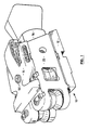
- Figure 1 is a general perspective view of a roller entry guide.
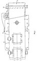
- Figure 2 is a side view of he roller entry guide shown in Figure 1.
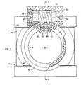
- Figure 3 is an end elevation of the roller entry guide shown in Figure 2 taken in the direction of arrow A in Figure 2 with portions removed for clarity.
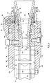
- Figure 4 is a section on the line 4-4 of Figure 3.
- Figure 5 is a plan view, with the top plate removed and partly in section, of the roller entry guide shown in Figure 2.
- Figure 6 is a view of the underside of the top plate used on the guide shown in Figures 1 to 5.
- Referring now to the drawings, a
roller entry guide 10 comprises abase plate 12 and atop plate 14 which are located on opposite faces of a body member generally designated 16 and secured thereto by setscrews 50. Thebody member 16 is provided with a bore 1Tthat extends along the longitudinal axis of theguide 10 from arear face 19 to a contourednose 21. Aninlet chute 18 having athroat 20 of progressively reducing cross section is threaded into thebore 17 and secured by setscrews 23. - Projecting from the
rear face 19 of thebody 16 is anannular boss 36 that has amale thread 38 to cooperate with afemale thread 39 of acollar 40. The rear portion of thecollar 40 is flared to accommodate theinlet chute 18 and terminates in an outwardly directedcircumferential groove 72. - The
base plate 12 andtop plate 14 project laterally and forwardly beyond the perimeter ofbody 16 to provide upper and loweropposed surfaces opposed surfaces plates grooves 46 arranged in pairs on opposite sides of the longitudinal axis. Thegrooves 46 in each pair are parallel to one another and are inclined to the longitudinal axis of theroller entry guide 10. Thegrooves 46 on opposite sides of the longitudinal axis are inclined at equal but opposite angles to the longitudinal axis to converge rearwardly toward therear face 19 ofbody 16. - The
top plate 14 is provided with anupstanding boss 52 that projects rearwardly from thetop plate 14 and is provided with atransverse bore 54. Located in thebore 54 is aworm wheel 56 that is rotatably supported at opposite ends bybearings 58. Theworm wheel 56 is formed with ahexagonal recess 60 at each end to receive a standard hexagonal wrench. Aslot 48 is provided in the undersurface ofboss 52 to intersect thebore 54 and receive aring gear 62 that meshes with theworm wheel 56. Thering gear 62 is provided with internal splines 64that mesh withexternal splines 66 provided on the outer surface of thecollar 40. The splines 64-66 are orientated along the longitudinal axis of theroller entry guide 10 so that thecollar 40 may move along the longitudinal axis relative to thering gear 62. Longitudinal movement of thering gear 62 is prevented by opposed walls 68 of theslot 48 in the under surface of theboss 52. - Located between the top plate, and base plate 14-12 are a pair of
roller assemblies 22, each of which comprises anarm 24 carrying a pair ofrollers 26 spaced along the longitudinal axis of thearm 24. Each of therollers 26 is mounted on avertical spindle 30 and provided with conventional bearing assemblies for rotation about a vertical axis. - Projecting rearwardly from each of the
arms 24 is anextension 76 that is part circular in cross- section to accommodate thecollar 40 and allow rotation of the collar about the longitudinal axis. Eachextension 76 terminates in a transversely directedflange 74 that is received in thegroove 72 ofcollar 40. - Upper and
lower surfaces 78 80 respectively of theroller arms 24 are each provided with a pair ofupstanding ribs 82 that are complementary in shape to thegrooves 46 and co-operate with thegrooves 46 so that longitudinal displacement of thearms 24 induces a corresponding lateral displacement. Each of therollers 26 is waisted so that opposedrollers 26 define a passage for rod passing through thechute 18 to the roll. For close control of the entry of the rod into the roll of the mill the spacing between the opposed surfaces of therollers 26 should correspond to the nominal diameter of the rod. Theguide 10 permits adjustment of this spacing during passage of the rod to accommodate minor variations in stock size. - Adjustment of the spacing between the
rollers 26 is achieved by rotation of theworm wheel 56 in thebore 54. Upon rotation of the worm wheel, thering gear 62 rotates about the longitudinal axis and causes a corresponding rotation of thecollar 40. Such rotation causesintermeshing threads annular boss 36, andcollar 40 to induce longitudinal displacement of thecollar 40. This motion is transmitted to theroller arms 24 through theflanges 74 to cause a corresponding longitudinal displacement of the roller assemblies. The co-operating grooves andribs 82 cause the roller assemblies to move laterally upon longitudinal displacement and thereby alter the gap between the rollers. However, because theroller arms 24 are supported at two locations by the grooves, the two arms remain parallel to one another so that the spacing between the front and rear pairs ofrollers 26 remains constant. - The disposition of the ribs and projections ensures that adequate lateral support is provided for the roller assemblies to resist the lateral forces produced by the rod material passing through the
roller entry guide 10 whilst at the same time ensuring that the sets of rollers remain parallel at all times. The worm and wheel arrangement permits adjustment of the roller entry guides from the side of the guide without interrupting the flow of material and can be used to either increase or decrease the space between tne rollers depending upon the direction of rotation of the worm wheel.
Claims (7)
Priority Applications (1)
| Application Number | Priority Date | Filing Date | Title |
|---|---|---|---|
| AT84306310T ATE39224T1 (en) | 1983-09-19 | 1984-09-14 | ROLL INTRODUCTION. |
Applications Claiming Priority (2)
| Application Number | Priority Date | Filing Date | Title |
|---|---|---|---|
| CA436955 | 1983-09-19 | ||
| CA000436955A CA1237299A (en) | 1983-09-19 | 1983-09-19 | Roller entry guide |
Publications (2)
| Publication Number | Publication Date |
|---|---|
| EP0143523A1 EP0143523A1 (en) | 1985-06-05 |
| EP0143523B1 true EP0143523B1 (en) | 1988-12-14 |
Family
ID=4126099
Family Applications (1)
| Application Number | Title | Priority Date | Filing Date |
|---|---|---|---|
| EP84306310A Expired EP0143523B1 (en) | 1983-09-19 | 1984-09-14 | Roller entry guide |
Country Status (6)
| Country | Link |
|---|---|
| EP (1) | EP0143523B1 (en) |
| JP (1) | JPS60106548A (en) |
| KR (1) | KR850002047A (en) |
| AT (1) | ATE39224T1 (en) |
| CA (1) | CA1237299A (en) |
| DE (1) | DE3475601D1 (en) |
Cited By (1)
| Publication number | Priority date | Publication date | Assignee | Title |
|---|---|---|---|---|
| WO2010072707A1 (en) | 2008-12-22 | 2010-07-01 | Danieli & C. Officine Meccaniche Spa | Adjustment device for guide rollers and relative adjustment method |
Families Citing this family (5)
| Publication number | Priority date | Publication date | Assignee | Title |
|---|---|---|---|---|
| KR100787586B1 (en) * | 2001-07-11 | 2007-12-21 | 주식회사 포스코 | Strip Front Guide Apparatus Of Entry Guide |
| CN102039318B (en) * | 2009-10-10 | 2013-07-03 | 鞍钢股份有限公司 | Heavy rail running guiding device |
| CN101954385B (en) * | 2010-09-16 | 2013-09-11 | 江苏永钢集团有限公司 | Intermediate transitional roller guide device |
| WO2015107477A1 (en) | 2014-01-16 | 2015-07-23 | Danieli & C. Officine Meccaniche S.P.A. | Guide device for rolling long metal products |
| CN112547813B (en) * | 2020-11-26 | 2021-08-31 | 广州众山精密科技有限公司 | Position guide device for preventing long strip from deviating |
Citations (1)
| Publication number | Priority date | Publication date | Assignee | Title |
|---|---|---|---|---|
| DE8226070U1 (en) * | 1983-01-20 | Centro-Morgardshammer GmbH, 4150 Krefeld | Double roller guide for rolling mills |
Family Cites Families (8)
| Publication number | Priority date | Publication date | Assignee | Title |
|---|---|---|---|---|
| GB191019657A (en) * | 1910-08-23 | 1911-06-15 | James Louis Riley | An Improved Rolling Mill Guide Box. |
| FR1151859A (en) * | 1956-06-25 | 1958-02-06 | Calumet & Hecla | Tube spinning process and industry |
| DE1173423B (en) * | 1962-09-06 | 1964-07-09 | Kloeckner Werke Ag | Walzgutfuehrungsgehaeuse |
| US4088333A (en) * | 1976-05-03 | 1978-05-09 | Nobile Alfred Francis | Jaws, guiding base plates and adjusting mechanism for chucks |
| IT1115518B (en) * | 1977-04-21 | 1986-02-03 | Innocenti Santeustacchio Spa | ENTRANCE GUIDE FOR PERFORATOR-LAMINATE |
| DE2912045A1 (en) * | 1978-03-30 | 1979-10-11 | Bartin Ltd | DETACHABLE WIRE GRIP DEVICE |
| DE2965336D1 (en) * | 1979-01-24 | 1983-06-16 | Kotobuki Sangyo | A centering and cramping adjusting mechanism for adjusting the clearance between sub-guide rollers, for use in a material guiding apparatus of a rolling mill |
| EP0103667B1 (en) * | 1982-09-16 | 1986-04-30 | Centro-Morgardshammar GmbH | Double roller guide for rolling mills |
-
1983
- 1983-09-19 CA CA000436955A patent/CA1237299A/en not_active Expired
-
1984
- 1984-09-14 AT AT84306310T patent/ATE39224T1/en not_active IP Right Cessation
- 1984-09-14 DE DE8484306310T patent/DE3475601D1/en not_active Expired
- 1984-09-14 EP EP84306310A patent/EP0143523B1/en not_active Expired
- 1984-09-19 JP JP59196485A patent/JPS60106548A/en active Pending
- 1984-09-19 KR KR1019840005732A patent/KR850002047A/en not_active Application Discontinuation
Patent Citations (1)
| Publication number | Priority date | Publication date | Assignee | Title |
|---|---|---|---|---|
| DE8226070U1 (en) * | 1983-01-20 | Centro-Morgardshammer GmbH, 4150 Krefeld | Double roller guide for rolling mills |
Cited By (1)
| Publication number | Priority date | Publication date | Assignee | Title |
|---|---|---|---|---|
| WO2010072707A1 (en) | 2008-12-22 | 2010-07-01 | Danieli & C. Officine Meccaniche Spa | Adjustment device for guide rollers and relative adjustment method |
Also Published As
| Publication number | Publication date |
|---|---|
| JPS60106548A (en) | 1985-06-12 |
| CA1237299A (en) | 1988-05-31 |
| KR850002047A (en) | 1985-05-06 |
| ATE39224T1 (en) | 1988-12-15 |
| DE3475601D1 (en) | 1989-01-19 |
| EP0143523A1 (en) | 1985-06-05 |
Similar Documents
| Publication | Publication Date | Title |
|---|---|---|
| EP0932462B1 (en) | Improved wire straightening device | |
| EP0930112B1 (en) | Spring manufacturing machine | |
| EP0143523B1 (en) | Roller entry guide | |
| EP0202377A1 (en) | Rolling mill guiding unit | |
| US4700875A (en) | Roller entry guide | |
| US4875354A (en) | Machine for adjustable longitudinal corrugating of sheet materials | |
| US4680953A (en) | Roller entry guide relating to a rod mill | |
| US4649986A (en) | Device for adjusting the width of the gap between the rolls of a continuous casting facility | |
| US5937689A (en) | Triple roller entry guide | |
| US4400963A (en) | Roller entry guide for angles | |
| CN115041556B (en) | Metal section molding machine | |
| GB2057933A (en) | Straightening | |
| US4727739A (en) | Box to separate rolled stock | |
| US3402681A (en) | Strudel dough plant | |
| CN206963402U (en) | A kind of crudefiber crop stalk milling roller grinding pressure and back lash automatic adjusting mechanism | |
| CN205290564U (en) | Feeder of centerless grinding machine | |
| JPS6336914A (en) | Roller guide for h shape steel | |
| JPH0328963Y2 (en) | ||
| US3709346A (en) | Roller guide | |
| EP0039063B1 (en) | Rotary rolling mill and method for rolling of tubular products | |
| US6237387B1 (en) | Entrance roller guide apparatus | |
| RU2080948C1 (en) | Apparatus for making corrugated strips | |
| CN209598123U (en) | A kind of cold headers blank guide rail assembly | |
| JPH10180336A (en) | Three roll guide | |
| CN219401768U (en) | Numerical control type three-roller straightener |
Legal Events
| Date | Code | Title | Description |
|---|---|---|---|
| PUAI | Public reference made under article 153(3) epc to a published international application that has entered the european phase |
Free format text: ORIGINAL CODE: 0009012 |
|
| AK | Designated contracting states |
Designated state(s): AT BE CH DE FR GB IT LI LU NL SE |
|
| 17P | Request for examination filed |
Effective date: 19851129 |
|
| 17Q | First examination report despatched |
Effective date: 19861114 |
|
| GRAA | (expected) grant |
Free format text: ORIGINAL CODE: 0009210 |
|
| AK | Designated contracting states |
Kind code of ref document: B1 Designated state(s): AT BE CH DE FR GB IT LI LU NL SE |
|
| PG25 | Lapsed in a contracting state [announced via postgrant information from national office to epo] |
Ref country code: SE Effective date: 19881214 Ref country code: NL Effective date: 19881214 Ref country code: BE Effective date: 19881214 Ref country code: AT Effective date: 19881214 |
|
| REF | Corresponds to: |
Ref document number: 39224 Country of ref document: AT Date of ref document: 19881215 Kind code of ref document: T |
|
| ITF | It: translation for a ep patent filed |
Owner name: ING. C. GREGORJ S.P.A. |
|
| REF | Corresponds to: |
Ref document number: 3475601 Country of ref document: DE Date of ref document: 19890119 |
|
| ET | Fr: translation filed | ||
| NLV1 | Nl: lapsed or annulled due to failure to fulfill the requirements of art. 29p and 29m of the patents act | ||
| PGFP | Annual fee paid to national office [announced via postgrant information from national office to epo] |
Ref country code: SE Payment date: 19890908 Year of fee payment: 6 |
|
| PG25 | Lapsed in a contracting state [announced via postgrant information from national office to epo] |
Ref country code: LU Free format text: LAPSE BECAUSE OF NON-PAYMENT OF DUE FEES Effective date: 19890930 |
|
| PLBE | No opposition filed within time limit |
Free format text: ORIGINAL CODE: 0009261 |
|
| STAA | Information on the status of an ep patent application or granted ep patent |
Free format text: STATUS: NO OPPOSITION FILED WITHIN TIME LIMIT |
|
| 26N | No opposition filed | ||
| PGFP | Annual fee paid to national office [announced via postgrant information from national office to epo] |
Ref country code: GB Payment date: 19900803 Year of fee payment: 7 |
|
| PGFP | Annual fee paid to national office [announced via postgrant information from national office to epo] |
Ref country code: FR Payment date: 19900919 Year of fee payment: 7 |
|
| PGFP | Annual fee paid to national office [announced via postgrant information from national office to epo] |
Ref country code: CH Payment date: 19900925 Year of fee payment: 7 |
|
| ITTA | It: last paid annual fee | ||
| PGFP | Annual fee paid to national office [announced via postgrant information from national office to epo] |
Ref country code: LU Payment date: 19901002 Year of fee payment: 7 |
|
| PGFP | Annual fee paid to national office [announced via postgrant information from national office to epo] |
Ref country code: DE Payment date: 19901031 Year of fee payment: 7 |
|
| PG25 | Lapsed in a contracting state [announced via postgrant information from national office to epo] |
Ref country code: GB Effective date: 19910914 |
|
| PG25 | Lapsed in a contracting state [announced via postgrant information from national office to epo] |
Ref country code: LI Effective date: 19910930 Ref country code: CH Effective date: 19910930 |
|
| GBPC | Gb: european patent ceased through non-payment of renewal fee | ||
| PG25 | Lapsed in a contracting state [announced via postgrant information from national office to epo] |
Ref country code: FR Effective date: 19920529 |
|
| REG | Reference to a national code |
Ref country code: CH Ref legal event code: PL |
|
| PG25 | Lapsed in a contracting state [announced via postgrant information from national office to epo] |
Ref country code: DE Effective date: 19920602 |
|
| REG | Reference to a national code |
Ref country code: FR Ref legal event code: ST |