EP0143358A2 - Regelmethode und Vorrichtung zu ihrer Realisierung - Google Patents
Regelmethode und Vorrichtung zu ihrer Realisierung Download PDFInfo
- Publication number
- EP0143358A2 EP0143358A2 EP84113143A EP84113143A EP0143358A2 EP 0143358 A2 EP0143358 A2 EP 0143358A2 EP 84113143 A EP84113143 A EP 84113143A EP 84113143 A EP84113143 A EP 84113143A EP 0143358 A2 EP0143358 A2 EP 0143358A2
- Authority
- EP
- European Patent Office
- Prior art keywords
- room temperature
- heating device
- heating
- equipment
- surface temperature
- Prior art date
- Legal status (The legal status is an assumption and is not a legal conclusion. Google has not performed a legal analysis and makes no representation as to the accuracy of the status listed.)
- Withdrawn
Links
- 238000000034 method Methods 0.000 title claims abstract description 20
- 230000001105 regulatory effect Effects 0.000 title claims description 10
- 238000010438 heat treatment Methods 0.000 claims abstract description 80
- 230000000694 effects Effects 0.000 claims abstract description 18
- 230000002159 abnormal effect Effects 0.000 description 1
- 230000002411 adverse Effects 0.000 description 1
- 238000009529 body temperature measurement Methods 0.000 description 1
- 230000001627 detrimental effect Effects 0.000 description 1
- 238000005259 measurement Methods 0.000 description 1
- 238000013021 overheating Methods 0.000 description 1
- 230000000630 rising effect Effects 0.000 description 1
- 238000009423 ventilation Methods 0.000 description 1
Images
Classifications
-
- G—PHYSICS
- G05—CONTROLLING; REGULATING
- G05D—SYSTEMS FOR CONTROLLING OR REGULATING NON-ELECTRIC VARIABLES
- G05D23/00—Control of temperature
- G05D23/19—Control of temperature characterised by the use of electric means
- G05D23/20—Control of temperature characterised by the use of electric means with sensing elements having variation of electric or magnetic properties with change of temperature
-
- G—PHYSICS
- G05—CONTROLLING; REGULATING
- G05D—SYSTEMS FOR CONTROLLING OR REGULATING NON-ELECTRIC VARIABLES
- G05D23/00—Control of temperature
- G05D23/19—Control of temperature characterised by the use of electric means
- G05D23/1927—Control of temperature characterised by the use of electric means using a plurality of sensors
- G05D23/193—Control of temperature characterised by the use of electric means using a plurality of sensors sensing the temperaure in different places in thermal relationship with one or more spaces
- G05D23/1931—Control of temperature characterised by the use of electric means using a plurality of sensors sensing the temperaure in different places in thermal relationship with one or more spaces to control the temperature of one space
Definitions
- the subject of the invention is a method of regulation for governing electrical heating e q 4jpment in relation with the heating of room space.
- a further subject of the invention is equipment for the realisation of the method
- the electrical heating equipment in connection with this application mainly consists of electrical heating equipment located in the room space in direct association with the room air, essentially wall-mounted heating radiators or simmilar equipment.
- thermostat in which full heating effect is led to the heating device until the thermostat cuts off the power-supply, causes a relatively high rise in surface temperature during the heating period, and, if the the thermostat is covered, can even constitute a fire hazard.
- thermostat which is sited with the heating device commonly functions on the basis of a bimetallic cutout and the temperature observed in the vicinity of the heating device and not upon the temperature prevailing in the room space to be heated.
- the bimetal cutouts used make audible sounds when the heating equipment is switched on and also when.it is switched off and this cause audible disturbance and uncertainty to the user of the equipment.
- the operation of the bimetallic thermostat causes interference in the operation of certain telecommunications equipment such as radio receivers, televisions and so on.
- the bimetallic cutout in the thermostat does not keep to its setting in the passage of time, the cutoff temperature changes which means that it hunts on the measuring scale and the user of the equipment must take this into account by carrying out calibration from time to time with the aid of room temperature measurements.
- the purpose of the invention put forward is to eradicate the disadvantges described above and to bring about a new method of regulation and equipment, primarily for governing room-orientated electrical heating equipment,in order that the aforementioned detrimental effects do not occur.
- the regulation method and equipment according to the invention is based on the regulation of the heating equipment surface temperature so that the surface temperature is kept as low as possible relative to the heating effect required. Further, in accordance with the invention, the surface temperature of the heating equipment is not allowed to rise above the allowed and set maximum value. Furthermore, according to one application of the invention, when the speed of change in room temperature exceeds a certain value, for example as the result of momentary ventilation, the surface temperature is fundamentally held constant for a certain period and the heating effect of the heating equipment is only regulated according to the changed room temperature after the period referred to.
- a merit of the invention is that the surface temperature of the heating equipment always remains sufficiently low and in every circumstance at a safe level. Overheating of the heating equipment cannot occur and nor does the electrical equipment lead to fire hazard; the surface temperature of the heating equipment is also at a pleasant level from the point of view of the user. Further, in utilising the electronic microprocessor measuring and control system in the heating equipment the regulation is precise and permanent because the regulation is based on the actual temperature prevailing in the room space.
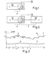
- Fig. 1 the regulation method and equipment in accordance with the invention for electrical heating device 1 can be seen, as for the regulation of a heating radiator mounted to a room space wall.
- the heating device 1 is furnished with a governing device 4 in order to regulate the heating effect of the heating device.
- the regulating equipment includes the surface temperature sensor 2 located on the surface of heating device 1, the temperature sensor 3 arranged to measure the temperature of the room space and the governing device 4, such as the microprocessor with its room temperature setting device 5.
- the sensor 3 measuring the room temperature is located to advantage fundamentally in a separate position from the heating device 1 so that it measures particularly the actual room temperature.
- Fig. 3 the operation of the regulating method according to the invention is presented graphically; the vertical axis represents temperature and the horizontal axis time.
- the straight line T a represents the desired setting value for room temperature, equivalent to the temperature setting value , for example 21°C, at the setting device 5 of the equipment in Fig. 1.
- the curve T h depicts the actual value of the room temperature as measured by the room temperature sensor 3 in accordance with Fig. 1.
- the curve T p depicts the actual surface temperature of the heating device 1 which is measured with the surface temperature sensor 2 in the equipment according to Fi g. 1.
- the stepped line T as depicts the setting value of the equipment surface temperature and also the heating effect P.
- the heating effect P of the heating device 1 is governed according to the room temperature T h and time t so that when T h falls below the room temperature setting value T a (cycle 0 - t k ) the surface temperature T p is raised to a known extent ⁇ T p for a known time period ⁇ t, that is a corresponding extra heating effect is supplied to the heating device.
- the room temperature T h exceeds the room temperature setting value T the surface temperature T of the heating device is reduced to a known extent ⁇ T p for a known time perion ⁇ t, for example in Fig. 3 for a time cycle t k - t l .
- the desired'setting value T a is attained with as low a surface temperature as possible and with small changes in surface temperature.
- the control of the effect of the heater is thus performed on the basis of the surface temperature Tp.which is governed according to the governing device 4, that is in accordance with the internal temperature setting T calculated by computer.
- T p exceeds the setting T as the power is cut off (the descending stages of the steps in the figure); when it falls below the setting the power is reconnected (rising steps). Then T p and thus also T h follow the setting T as (bottom part of the figure).
- T p and thus also T h follow the setting T as (bottom part of the figure).
- the surface temperature setting T as is increased ⁇ T p , but however so that the maximum setting T pmax for example 80°C,is not exceeded. If after the stated time ⁇ t the room temperature T h is higher than the room temperature setting T a the surface temperature setting T as is lowered, but not however lower than the room temperature setting T.
- the time period ⁇ t can be regulated correspondingly with the room in question by measuring the time between t k -t l of the surface temperature T as maximum and minimum values, when it is some factor of ⁇ t if ⁇ t is sufficiently short. A measured time is is set for the cycle ⁇ t of the room in question or some part of its whole value.
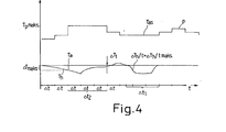
- a rapid change in room temperature is an abnormal phenomenon and is eliminated according to the invention by measuring the speed of change ⁇ T h/ t. If it is greater than the known limiting value ⁇ T h/ t max. the surface temperature setting T as is kept essentially constant for a known period ⁇ t 1 , and only after this is regulation of the surface temperature setting begun if required. This is illustrated graphically in Fig. 4.
- the room temperature change speed ⁇ T h /t measured as time cycle ⁇ t 1 is greater than the the known limiting value ⁇ T h /tmax. Then during a corresponding time the surface temperature setting T as is kept constant and after the room temperature has returned to a normal level after the time period ⁇ t 1 it is returmed to normal regulation.
- the heating effect of the heating equipment is regulated by governing the number of alternating current halfwaves 6 fed to the heating equipment,by means of the regulator 4.
- the aforementioned halfwaves are passed into the equipment for known time periods,for example from fractions of a second to several seconds, and the halfwaves cut for known time periods, for example fractions of a second to several seconds.
- the regulation of the surface temperature is then performed by means of ON/OFF regulation and the setting of the internal surface temperature T as fundamentally corresponds to the heating effect P in accordance with Fig. 4.
- the equipment also includes another heating device 7 with its surface temperature sensor 8.
- the governing device 4 with its setting facility 5 of the previous heating equipment 1 is arranged to control the second heating equipment 7 surface temperature T pin the manner described above.
- the temperature sensors 3 monitor the room temperature and are essentially located separate from the heating equipment 1 so that they measure the actual temperature of the room without any kind of interference.
- Naturally temperature sensors 3 may also be located in association with the heating equipment or in its immediate vicinity in the convential manner as long as it is ensured that the heating equipment does not interfere with the measurement of the room temperature or that interference caused by the heating equipment is compensated for.
Landscapes
- Engineering & Computer Science (AREA)
- Physics & Mathematics (AREA)
- General Physics & Mathematics (AREA)
- Automation & Control Theory (AREA)
- Remote Sensing (AREA)
- Central Heating Systems (AREA)
- Air Transport Of Granular Materials (AREA)
- Control And Other Processes For Unpacking Of Materials (AREA)
- Electrical Discharge Machining, Electrochemical Machining, And Combined Machining (AREA)
- Domestic Hot-Water Supply Systems And Details Of Heating Systems (AREA)
- Control Of Resistance Heating (AREA)
- Heat-Pump Type And Storage Water Heaters (AREA)
- Control Of Temperature (AREA)
Applications Claiming Priority (2)
| Application Number | Priority Date | Filing Date | Title |
|---|---|---|---|
| FI834014 | 1983-11-01 | ||
| FI834014A FI74554C (fi) | 1983-11-01 | 1983-11-01 | Regleringsfoerfarande. |
Publications (2)
| Publication Number | Publication Date |
|---|---|
| EP0143358A2 true EP0143358A2 (de) | 1985-06-05 |
| EP0143358A3 EP0143358A3 (de) | 1985-12-04 |
Family
ID=8518027
Family Applications (1)
| Application Number | Title | Priority Date | Filing Date |
|---|---|---|---|
| EP84113143A Withdrawn EP0143358A3 (de) | 1983-11-01 | 1984-10-31 | Regelmethode und Vorrichtung zu ihrer Realisierung |
Country Status (4)
| Country | Link |
|---|---|
| EP (1) | EP0143358A3 (de) |
| JP (1) | JPS60181543A (de) |
| FI (1) | FI74554C (de) |
| NO (1) | NO844337L (de) |
Cited By (4)
| Publication number | Priority date | Publication date | Assignee | Title |
|---|---|---|---|---|
| EP0556168A1 (de) * | 1992-01-20 | 1993-08-18 | Lvi Produkter Ab | Thermostat |
| GB2309552A (en) * | 1996-01-25 | 1997-07-30 | Rwl Consultants Ltd | Fail-safe monitoring system |
| IT201700076925A1 (it) * | 2017-07-07 | 2019-01-07 | Carlo Alberto Zenobi | Sistema di riscaldamento |
| WO2019008544A3 (en) * | 2017-07-07 | 2019-02-21 | Carlo Alberto Zenobi | HEATING SYSTEM COMPRISING A PLURALITY OF RADIANT HEATING PANELS |
Family Cites Families (5)
| Publication number | Priority date | Publication date | Assignee | Title |
|---|---|---|---|---|
| DE2219897A1 (de) * | 1972-04-19 | 1973-10-31 | Siemens Ag | Regeleinrichtung |
| US4172555A (en) * | 1978-05-22 | 1979-10-30 | Levine Michael R | Adaptive electronic thermostat |
| US4393919A (en) * | 1980-09-02 | 1983-07-19 | Anderson Cary R | Thermal energy meter |
| US4396148A (en) * | 1981-10-23 | 1983-08-02 | Heat-Timer Corporation | Heating system control device |
| DE3213845A1 (de) * | 1982-04-15 | 1983-10-27 | Rump, Hanns, 4750 Unna-Massen | Vorrichtung zur erfassung der von heizkoerpern oder fussbodenheizungen abgegebenen waermemenge zum zwecke der heizkostenverteilung und zur gleichzeitigen regelung der heizkoerperleistung |
-
1983
- 1983-11-01 FI FI834014A patent/FI74554C/fi not_active IP Right Cessation
-
1984
- 1984-10-31 NO NO844337A patent/NO844337L/no unknown
- 1984-10-31 EP EP84113143A patent/EP0143358A3/de not_active Withdrawn
- 1984-11-01 JP JP59231110A patent/JPS60181543A/ja active Pending
Cited By (5)
| Publication number | Priority date | Publication date | Assignee | Title |
|---|---|---|---|---|
| EP0556168A1 (de) * | 1992-01-20 | 1993-08-18 | Lvi Produkter Ab | Thermostat |
| GB2309552A (en) * | 1996-01-25 | 1997-07-30 | Rwl Consultants Ltd | Fail-safe monitoring system |
| GB2309552B (en) * | 1996-01-25 | 2000-01-19 | Rwl Consultants Ltd | Failsafe system monitoring |
| IT201700076925A1 (it) * | 2017-07-07 | 2019-01-07 | Carlo Alberto Zenobi | Sistema di riscaldamento |
| WO2019008544A3 (en) * | 2017-07-07 | 2019-02-21 | Carlo Alberto Zenobi | HEATING SYSTEM COMPRISING A PLURALITY OF RADIANT HEATING PANELS |
Also Published As
| Publication number | Publication date |
|---|---|
| FI834014A0 (fi) | 1983-11-01 |
| FI834014L (fi) | 1985-05-02 |
| JPS60181543A (ja) | 1985-09-17 |
| EP0143358A3 (de) | 1985-12-04 |
| NO844337L (no) | 1985-05-02 |
| FI74554C (fi) | 1988-02-08 |
| FI74554B (fi) | 1987-10-30 |
Similar Documents
| Publication | Publication Date | Title |
|---|---|---|
| US5605280A (en) | Self-balancing variable air volume heating and cooling system | |
| US6021252A (en) | HVAC fan-powered terminal unit having preset fan CFM | |
| US20070006603A1 (en) | Systems and methods for a temperature-controlled electrical outlet | |
| EP0187629B1 (de) | Methode zur Regelung der Aufheizung von Flüssigkeit in einem Kochgefäss | |
| KR900001881B1 (ko) | 증압식 조리기구내의 조리과정 제어장치 및 그 방법 | |
| US4793553A (en) | Infrared thermostat control | |
| US4939987A (en) | Humidity control system | |
| JPS63317109A (ja) | 料理用なべの加熱素子の熱効率調整装置 | |
| CA2242829C (en) | Air heating system | |
| EP0143358A2 (de) | Regelmethode und Vorrichtung zu ihrer Realisierung | |
| KR100357326B1 (ko) | 전기장치내의팬의작동전압을제어하기위한방법 | |
| US4620083A (en) | Device for regulating the cooking process in a cooking vessel | |
| JPS5478850A (en) | Temperature control circuit for air conditioner | |
| US4279381A (en) | Method for uniformly heating a multi-level building | |
| EP0100214A2 (de) | Lüftungsregelung | |
| GR3020128T3 (en) | Heating device and its control. | |
| FI85330C (fi) | Foerfarande foer styrning av en elektrisk ugn | |
| GB2007877A (en) | Electric hairdrier | |
| CA1286019C (en) | Method of regulating room temperature and means for performing this method | |
| US4939344A (en) | Electric sauna oven with shield for transmitting heat radiation to detector | |
| SU812250A1 (ru) | Устройство дл регулировани микроклиматажиВОТНОВОдчЕСКОгО пОМЕщЕНи | |
| GB2101773A (en) | Improvements in and relating to heaters | |
| JP2003042503A (ja) | 空調自動調整装置 | |
| EP3662212B1 (de) | Verfahren zur regelung einer konditionierungsvorrichtung | |
| US2870965A (en) | Compensated anticipating thermostat |
Legal Events
| Date | Code | Title | Description |
|---|---|---|---|
| PUAI | Public reference made under article 153(3) epc to a published international application that has entered the european phase |
Free format text: ORIGINAL CODE: 0009012 |
|
| AK | Designated contracting states |
Designated state(s): AT BE CH DE FR GB IT LI LU NL SE |
|
| PUAL | Search report despatched |
Free format text: ORIGINAL CODE: 0009013 |
|
| AK | Designated contracting states |
Designated state(s): AT BE CH DE FR GB IT LI LU NL SE |
|
| 17P | Request for examination filed |
Effective date: 19860205 |
|
| STAA | Information on the status of an ep patent application or granted ep patent |
Free format text: STATUS: THE APPLICATION IS DEEMED TO BE WITHDRAWN |
|
| 18D | Application deemed to be withdrawn |
Effective date: 19880503 |
|
| RIN1 | Information on inventor provided before grant (corrected) |
Inventor name: HAEMAELAEINEN, ILKKA Inventor name: KAINULAINEN, OSMO |