EP0143322A2 - Gaslaserrohr-Anordnung - Google Patents
Gaslaserrohr-Anordnung Download PDFInfo
- Publication number
- EP0143322A2 EP0143322A2 EP84112702A EP84112702A EP0143322A2 EP 0143322 A2 EP0143322 A2 EP 0143322A2 EP 84112702 A EP84112702 A EP 84112702A EP 84112702 A EP84112702 A EP 84112702A EP 0143322 A2 EP0143322 A2 EP 0143322A2
- Authority
- EP
- European Patent Office
- Prior art keywords
- plasma tube
- gas laser
- tube
- assembly according
- plasma
- Prior art date
- Legal status (The legal status is an assumption and is not a legal conclusion. Google has not performed a legal analysis and makes no representation as to the accuracy of the status listed.)
- Withdrawn
Links
Images


Classifications
-
- H—ELECTRICITY
- H01—ELECTRIC ELEMENTS
- H01S—DEVICES USING THE PROCESS OF LIGHT AMPLIFICATION BY STIMULATED EMISSION OF RADIATION [LASER] TO AMPLIFY OR GENERATE LIGHT; DEVICES USING STIMULATED EMISSION OF ELECTROMAGNETIC RADIATION IN WAVE RANGES OTHER THAN OPTICAL
- H01S3/00—Lasers, i.e. devices using stimulated emission of electromagnetic radiation in the infrared, visible or ultraviolet wave range
- H01S3/02—Constructional details
- H01S3/03—Constructional details of gas laser discharge tubes
Definitions
- the present invention relates to an improved gas laser tube assembly for a C0 2 , CO, or other gas arson, laser.
- An object of the present invention is to provide an improved gas laser tube assembly which avoids these problems associated with known laser tube assemblies. More particularly, an object of the invention is to provide a gas laser tube assembly which permits pulling out the laser tube without destroying the laser alignment or changing the alignment of the laser mirrors.
- a further object of the invention is to provide a gas laser tube assembly wherein it is unnecessary to break the seal to the liquid coolant as in the prior art arrangements to clean, repair or replace electrodes.
- Another object of the invention is to provide a gas laser tube assembly wherein the opposite ends of the plasma tube are subjected to essentially equal cooling and wherein the electrodes at the respective ends are of equal mass thereby allowing either end of the tube to function as a cathode so that the laser tube can be run on either alternating or direct current. While most gas lasers are operated with direct current, alternating current may be desirable in certain low cost applications or where 120 pulses per second are desired. In the past, gas laser tubes have generally not been balanced in mass and cooling at each end.
- a still further object of the present invention is to provide a gas laser tube assembly which results in improved optical axis alignment between the plasma tube and the adjacent end structure of the assembly.
- a gas laser tube assembly comprising an elongated gas laser plasma tube, a member positioned adjacent one end of the elongated gas laser plasma tube in spaced relationship thereto along the longitudinal axis of the plasma tube, and releasable connection means extending between and releasably connecting the one end of the plasma tube and the member in spaced relationship along the longitudinal axis of the plasma tube, the connection means and the member being arranged for telescoping movement with respect to one another in either direction along the longitudinal axis of the plasma tube at least upon release of the connection means thereby facilitating removal and installation of the plasma tube from the assembly.
- the member positioned adjacent the end of the elongated gas laser plasma tube includes a bore which serves as a gas port for conveying gas to or from the interior of the plasma tube by way of a cooperating passage provided in the releasable connection means.
- the bore in the member and the cooperating passage in the releasable connection means extend in a direction essentially coaxial with the longitudinal axis of the plasma tube.
- the bore in the member extends completely through the member and the end of the member opposite the plasma tube includes means for connecting a mirror or an additional gas laser plasma tube to the member.
- the releasable connection means includes a first part connected to the one end of the plasma tube and a second part releasably connected to the member with means being provided for releasably connecting the first and second parts to one another.
- the first part includes an electrode attached therewith, the electrode having a bore extending therethrough in a direction essentially coaxial with the longitudinal axis of the plasma tube.
- the one end of the plasma tube is bell-shaped to accommodate at least a portion of the electrode therein.
- the gas laser tube assembly of the disclosed embodiment further includes a cooling jacket surrounding the plasma tube in spaced relationship thereto so as to define a coolant passage between the cooling jacket and the plasma tube.
- Means are provided for connecting one end of the cooling jacket to the first part. More specifically, the outer surface of the one end of the cooling jacket is conically shaped and the means for connecting the one end of the cooling jacket to the first part includes a conical cooling jacket sealing ring surrounding the conically shaped one end of the cooling jacket and threadedly attached to the first part, a compression ring positioned between the sealing ring and the outer surface of the conically shaped one end of the cooling jacket and an 0-ring seal positioned between the first part and an end surface of the one end of the cooling jacket.
- the first part includes a passage for conveying a fluid coolant to or from the coolant passage.
- connection between the first part and the one end of the plasma tube is a releasable connection made by means of a plasma tube sealing ring which is threadedly attached to the first part with an 0-ring seal being positioned between the sealing ring and the first part and engaging the outer surface of the one end of the plasma tube.
- an assembly of the type described is provided at each end of the elongated gas laser plasma tube thereby facilitating removal and reassembly of the plasma tube for servicing the electrodes or cleaning the interior of the plasma tube without disrupting the intergrity of the coolant passage between the plasma tube and the outer cooling jacket and without requiring realignment of the laser. Also, with the uniform cooling provided by this overall arrangement and with the use of electrodes at each end having equal mass, the laser can be run on either alternating or direct current since it is balanced in mass and cooling at each end.
- the second part of the releasable connection means includes a tubular projection at its end opposite the plasma - tube.
- the tubular projection surrounds and is essentially coaxial with the bore in the second part and is telescopically positioned within the bore or gas port of the adjacent member.
- the releasable connection means includes means for releasably sealing the tubular projection in a gas-tight manner in the bore of the adjacent member.
- This means includes a tubular projection sealing ring threadedly attached to the adjacent member and an 0-ring seal positioned between the adjacent member and the sealing ring and engaging the outer surface of the tubular projection.
- the plasma tube upon release of the connection means the plasma tube can be moved laterally along the longitudinal axis of the plasma tube toward one adjacent member at a first end and away from an additional adjacent member at its second end so that the tubular projection at the second end moves out of the cooperating bore of the additional member. Thereafter, the second end of the plasma tube can be swung out of alignment with the gas port of the additional member. The plasma tube is then moved in the opposite direction to completely remove the plasma tube from the member adjacent its first end. Reinstallation of the plasma tube is accomplished in a similar fashion by reversing this sequence.
- the invention thus permits disassembly and reassembly without destroying the alignment of the mirrors or adjacent plasma tubes connected with the member and additional member.
- leading end of the tubular projection received in the gas port is inclined with respect to the longitudinal or optic axis of the plasma tube. This conditions the gas flow through the plasma tube and cuts down on internal stray radiation.
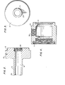
- FIG. 1 a gas laser tube assembly 1 according to the invention for a C0 2 , CO or other gas laser is illustrated in Figure 1.
- the assembly is formed of an elongated gas laser plasma tube 2, only the left end 3 of which is shown in the drawing, a member 4 positioned adjacent the end 3 of the plasma tube 2 in spaced relationship thereto along the longitudinal axis A-A of the plasma tube, and a releasable connecticn means 5 extending between and releasably connecting the end 3 of the plasma tube 2 and the member 4 in spaced relationship along the longitudinal axis A-A of the plasma tube.
- the releasable connection means 5 and the member 4 are arranged for telescoping movement with respect to one another in either direction along the longitudinal axis of the plasma tube at least upon release of the connection means thereby facilitating removal and installation of the plasma tube from the assembly.
- the releasable connection means 5 includes a first part 6 in the form of a master sealing ring connected to the end 3 of the plasma tube 2 by means of a plasma tube sealing ring 7 threadedly attached to the first part and an 0-ring seal 8 positioned between the sealing ring and the first part and engaging the outer surface of the end 3 of the plasma tube 2.
- the 0-ring seal When the 0-ring seal is compressed by the sealing ring 7 it sealingly engages the outer surface of the end 3 of the plasma tube 2 and supports the end 3 of the plasma tube within the central bore 9 of the first part 6.
- the releasable connection means 5 further includes a second part 10 formed as a gas port plug and electrode mount which is releasably connected to the first part 6 by means of cooperating screw threads 11 and 12 provided on the respective parts as illustrated in Figures 1, 2 and 4.
- the second part 10 includes a tubular projection 13 at its end opposite the plasma tube 2.
- the tubular projection 13 is telescopically positioned within a bore 14 of the member 4.
- the tubular projection 13 is releasably connected within the bore 14 of the member 4 by means of a tubular projection sealing ring 15 and an O-ring seal 16 of the releasable connection means 5.
- the sealing ring 15 is threadedly attached to the member 4 and the O-ring seal 16 is positioned between the member 4 and the sealing ring 15 and engages the outer surface of the tubular projection 13 in a gas-tight manner when compressed by the sealing ring. Because of the overqll length of the tubular projection 13 and also the fact that the bore 14 of the member 4 extends completely through the member, upon release of the compressive pressure on the 0-ring seal 16 by the sealing ring 15, the connection means 5 and the member 4 may be telescopically moved with respect to one another in either direction along the longitudinal axis A-A of the plasma tube 2 thereby facilitating removal and installation of the plasma tube from the assembly.
- the right end 17 (see figure 6) of the plasma tube 2 may also be provided with a like assembly (not shown).
- the members 4 at each end of the plasma tube 2 are spaced such that, at least after release of the compressive pressure of the tubular projection sealing rings on the respective 0-ring seals engaging the tubular projections, the subassembly of the plasma tube 2 with first and second parts 6 and 10 at the left end thereof and corresponding parts at the right end thereof can be moved in either direction along the longitudinal axis of the plasma tube to remove the tubular projection at one end from the bore of its adjacent member so the one end of the subassembly can be swung out of alignment with the bore and member to permit complete withdrawal of the tubular projection at the opposite end of the subassembly from the bore of its adjacent member. This can be done without changing the relative positions of the members 4.
- the gas laser tube assembly of the invention permits pulling out the laser tube without destroying
- the bore 14 of member 4 is in communication with the interior of the plasma tube 2 by way of a cooperating passage 18 provided in the second part 10 of the releasable connection means 5.
- the bore 14 and the cooperating passage 18 extend in a direction essentially coaxial with the longitudinal axis A-A of the plasma tube 2.
- the bore 14 extends completely through the member 4 with the end of the member 4 opposite the plasma tube 2 including means for connecting a mirror or an additional gas laser plasma tube 19 to the member 4.
- the means for connecting includes a sealing ring 20 and an 0-ring seal 21 of the type at the end of the member 4 adjacent the plasma tube 2.
- This arrangement permits a gas such as carbon dioxide to be conducted to or from the interior of the plasma tube 2 by way of a fitting 22 of the member 4 in communication with the bore 14.
- the leading end 23 of the tubular projection 13 in the bore 14 is inclined with respect to the optic axis of the gas laser tube to condition the gas flow through the tube and cut down on internal stray radiation.
- the leading end 23 is inclined at an angle of between 30 and 45 degrees with respect to the optic axis.
- the second part 10 of the releasable connection means 5 is also formed with screw threads 24 at its end adjacent the plasma tube 2 for mounting an electrode 24 thereto.
- the electrode 24 has a central bore extending therethrough in a direction essentially coaxial with the longitudinal axis of the plasma tube 2.
- Each end of the plasma tube 2 is bell-shaped as shown at 26 in Figure 1 to accommodate a coaxial, concentric electrode therein in the manner illustrated.
- the gas laser tube assembly 1 further includes a cooling jacket 27 surrounding the plasma tube 2 in spaced relationship thereto so as to define a coolant passage 28 between the cooling jacket and the plasma tube.
- the cooling jacket also provides structural support for the assembly because of its relatively thick wall.
- the cooling jacket has conically shaped ends 29 and 30. As shown in Figure 1, the left end 29 is connected to the first part 6 of the releasable connection means 5 by means of a conical cooling jacket sealing ring 31 surrounding the conically shaped end 29 and threadedly attached to the first part 6, a plastic compression ring 32 positioned between the sealing ring 31 and the outer surface of the end 29 of the cooling jacket, and an 0-ring seal 33 positioned between the first part 6 and an end surface 34 of the cooling jacket.
- the first part 6 includes a passage 35 for conveying fluid coolant such as a dielectric cooling oil to or from the coolant passage 28.
- the second part 10 at each end can be simply unscrewed from the first part 6 to clean, repair or replace the electrode 24 or to clean the interior of the plasma tube 2 without breaking the seal to the cooling oil.
- This procedure can be accomplished in a relatively short period, such as two hours, whereas in the past the removal and reassembly operation has required two days because the mirror mount had to be pulled off and the oil seal broken, the oil drained, and the laser realigned during reassembly.
- the plasma tube 2 is returned to its aligned position with respect to the adjacent members and the mirrors or other plasma tubes associated therewith.
- the use of a like gas laser tube assembly of the invention at each end of the plasma tube 2 also results in balanced mass and cooling at each end of the plasma tube. Therefore, the laser tube can be run on either alternating current or direct current. Alternating current may be desirable in low cost applications or where 120 laser pulses per second are desired.
- the plasma tube 2 and the cooling jacket 27 are each formed of a heat resistant glass such as Corning Pyrex glass precision bore tubing.
- the conically shaped ends 29 and 30 of the cooling jacket 27 are precision straightened under rollers at the glass annealing temperature with the ends of the tube being square to the bore so that the length of the cooling jacket as measured on one side of the tube does not vary more that .005 inch as the tube is rotated.
- the cooling jacket 27 is 60 inches in length with the bow between ends thereof being less than or equal to .020 inch and the out of roundness of the outer diameter of the tube being less than or equal to .010 inch.
- the wall thickness of the cooling jacket is 4.4mm.
- the plasma tube 2 in the disclosed embodiment has an overall 1 length of 64 and 1 6 inches and a wall thickness of 1.5 millimeters.
- the bell-shaped ends of the plasma tube are precision formed by being shrunk on to a mandrel so that excellent alignment of the plasma tube can be attained according to the invention by low skilled labor.
- the first and second parts 6 and 10 of the releasable connection means 5 and the member 4 are formed of 6061 aluminum alloy with the outer surfaces of the parts being provided with a soft anodized coating.
- the tubular projection sealing ring 15 and the conical cooling jacket sealing ring 31 are formed of brass.
- the electrode 24 is a copper electrode although other metals such as nickel may be employed.
Landscapes
- Physics & Mathematics (AREA)
- Electromagnetism (AREA)
- Engineering & Computer Science (AREA)
- Plasma & Fusion (AREA)
- Optics & Photonics (AREA)
- Lasers (AREA)
Applications Claiming Priority (2)
| Application Number | Priority Date | Filing Date | Title |
|---|---|---|---|
| US546741 | 1983-10-28 | ||
| US06/546,741 US4617667A (en) | 1983-10-28 | 1983-10-28 | Gas laser tube assembly |
Publications (2)
| Publication Number | Publication Date |
|---|---|
| EP0143322A2 true EP0143322A2 (de) | 1985-06-05 |
| EP0143322A3 EP0143322A3 (de) | 1987-06-03 |
Family
ID=24181811
Family Applications (1)
| Application Number | Title | Priority Date | Filing Date |
|---|---|---|---|
| EP84112702A Withdrawn EP0143322A3 (de) | 1983-10-28 | 1984-10-20 | Gaslaserrohr-Anordnung |
Country Status (2)
| Country | Link |
|---|---|
| US (1) | US4617667A (de) |
| EP (1) | EP0143322A3 (de) |
Cited By (1)
| Publication number | Priority date | Publication date | Assignee | Title |
|---|---|---|---|---|
| EP0342988A1 (de) * | 1988-05-19 | 1989-11-23 | Rofin-Sinar Inc. | Stromgaslaser-Entladungsrohr-Struktur |
Families Citing this family (6)
| Publication number | Priority date | Publication date | Assignee | Title |
|---|---|---|---|---|
| US4827485A (en) * | 1986-06-06 | 1989-05-02 | Lightwave Electronics Corp. | Diode pumped solid state laser |
| JPS6327081A (ja) * | 1986-07-18 | 1988-02-04 | Fanuc Ltd | ガスレ−ザ装置 |
| DE8914097U1 (de) * | 1989-11-29 | 1990-04-05 | Rofin-Sinar Laser GmbH, 2000 Hamburg | Axial durchströmter Gaslaser, insbesondere Hochleistungs-CO↓2↓-Laser |
| US5008593A (en) * | 1990-07-13 | 1991-04-16 | The United States Of America As Represented By The Secretary Of The Air Force | Coaxial liquid cooling of high power microwave excited plasma UV lamps |
| US5055741A (en) * | 1990-07-13 | 1991-10-08 | The United States Of America As Represented By The Secretary Of The Air Force | Liquid coolant for high power microwave excited plasma tubes |
| US5235251A (en) * | 1991-08-09 | 1993-08-10 | The United States Of America As Represented By The Secretary Of The Air Force | Hydraulic fluid cooling of high power microwave plasma tubes |
Family Cites Families (14)
| Publication number | Priority date | Publication date | Assignee | Title |
|---|---|---|---|---|
| US3361989A (en) * | 1964-03-09 | 1968-01-02 | Air Force Usa | Solid state optical laser |
| US3482183A (en) * | 1964-11-05 | 1969-12-02 | American Optical Corp | Laser apparatus |
| FR1496231A (fr) * | 1966-08-19 | 1967-09-29 | Comp Generale Electricite | Tête pour tube laser |
| FR1557756A (de) * | 1967-12-01 | 1969-02-21 | ||
| US3510801A (en) * | 1968-01-19 | 1970-05-05 | Trw Inc | Optical pump system for repetitive operation |
| US3518569A (en) * | 1968-08-09 | 1970-06-30 | Us Army | Circulating liquid cladding system for laser rods |
| DE1947286A1 (de) * | 1969-09-18 | 1971-04-01 | Messer Griesheim Gmbh | Laser-Einrichtung |
| US3652954A (en) * | 1970-07-10 | 1972-03-28 | Elias Snitzer | Laser device |
| US3665337A (en) * | 1970-07-17 | 1972-05-23 | Union Carbide Corp | Method and means for sealing laser rods |
| US3735282A (en) * | 1972-06-14 | 1973-05-22 | F Gans | Liquid-cooled, segmented glass laser |
| US3891945A (en) * | 1973-09-20 | 1975-06-24 | Us Air Force | Configuration for efficient cooling and excitation of high average power solid state lasers |
| US4150341A (en) * | 1976-12-28 | 1979-04-17 | The United States Of America As Represented By The Secretary Of The Navy | High input power laser device |
| DE2740606A1 (de) * | 1977-09-29 | 1979-04-05 | Messer Griesheim Gmbh | Gaslaser, insbesondere gastransportlaser, mit einer laserentladungsroehre |
| US4207541A (en) * | 1978-02-21 | 1980-06-10 | General Electric Company | Cooling jacket for laser flash lamps |
-
1983
- 1983-10-28 US US06/546,741 patent/US4617667A/en not_active Expired - Fee Related
-
1984
- 1984-10-20 EP EP84112702A patent/EP0143322A3/de not_active Withdrawn
Cited By (1)
| Publication number | Priority date | Publication date | Assignee | Title |
|---|---|---|---|---|
| EP0342988A1 (de) * | 1988-05-19 | 1989-11-23 | Rofin-Sinar Inc. | Stromgaslaser-Entladungsrohr-Struktur |
Also Published As
| Publication number | Publication date |
|---|---|
| EP0143322A3 (de) | 1987-06-03 |
| US4617667A (en) | 1986-10-14 |
Similar Documents
| Publication | Publication Date | Title |
|---|---|---|
| US4617667A (en) | Gas laser tube assembly | |
| EP0587275B1 (de) | Beleuchtungs- und Beobachtungseinheit | |
| US5210815A (en) | Hermetically sealed optical fiber feedthrough | |
| JP4121569B2 (ja) | 高出力プラズマベース反応種ジェネレータ | |
| US4628177A (en) | Arc welding torch | |
| EP1041602A2 (de) | Kühlsystem für eine dielektrisch behinderte Entladungslampe | |
| US5137553A (en) | Molecular jet separator | |
| US4054044A (en) | Seals for the passage of wire between regions of different pressure | |
| CA1228147A (en) | Gas laser tube assembly | |
| US6782184B2 (en) | Modular insertion device for process illumination and viewing | |
| CN216237282U (zh) | 管道零件内表面激光熔覆用的同轴送粉激光熔覆头 | |
| EP0072409B1 (de) | Düse für eine Plasmaspritzpistole | |
| US5385712A (en) | Modular chemical reactor | |
| US4120352A (en) | Device for connecting exchanger tubes to perforated plates | |
| US5789910A (en) | Molten metal inclusion sensor probes | |
| US5320238A (en) | End closure method and construction for non-metallic pressure vessels | |
| EP0283450B1 (de) | Laser-Kavität mit Trägerrohr für einen optisch gepumpten FIR-(im fernen Infrarot betriebenen)-Laser | |
| US5510935A (en) | Lens mounting technique | |
| JPH0218976A (ja) | 流動ガスレーザー放電構造 | |
| US4815095A (en) | Resonant laser cavity system | |
| US4788929A (en) | Fluid indicator for refrigeration system | |
| CN117810798A (zh) | 一种基于阵列光纤的激光输出头及其激光器 | |
| US5791563A (en) | Gas burner having a fixed head burner with a quartz nozzle, a spring and an end cap | |
| US6311902B1 (en) | Dispersion nozzle for gas delivery tube | |
| US5212708A (en) | Axial flow gas laser particularly high-power CO2 laser with DC excitation |
Legal Events
| Date | Code | Title | Description |
|---|---|---|---|
| PUAI | Public reference made under article 153(3) epc to a published international application that has entered the european phase |
Free format text: ORIGINAL CODE: 0009012 |
|
| AK | Designated contracting states |
Designated state(s): AT BE CH DE FR GB IT LI NL SE |
|
| 17P | Request for examination filed |
Effective date: 19851123 |
|
| PUAL | Search report despatched |
Free format text: ORIGINAL CODE: 0009013 |
|
| AK | Designated contracting states |
Kind code of ref document: A3 Designated state(s): AT BE CH DE FR GB IT LI NL SE |
|
| STAA | Information on the status of an ep patent application or granted ep patent |
Free format text: STATUS: THE APPLICATION IS DEEMED TO BE WITHDRAWN |
|
| 18D | Application deemed to be withdrawn |
Effective date: 19880503 |
|
| RIN1 | Information on inventor provided before grant (corrected) |
Inventor name: PENN, WAYNE MARION |