EP0143154A1 - Apparatus for supporting and calibrating tubular films of thermoplastics - Google Patents
Apparatus for supporting and calibrating tubular films of thermoplastics Download PDFInfo
- Publication number
- EP0143154A1 EP0143154A1 EP84106276A EP84106276A EP0143154A1 EP 0143154 A1 EP0143154 A1 EP 0143154A1 EP 84106276 A EP84106276 A EP 84106276A EP 84106276 A EP84106276 A EP 84106276A EP 0143154 A1 EP0143154 A1 EP 0143154A1
- Authority
- EP
- European Patent Office
- Prior art keywords
- flanks
- rings
- film tube
- diameter
- annular
- Prior art date
- Legal status (The legal status is an assumption and is not a legal conclusion. Google has not performed a legal analysis and makes no representation as to the accuracy of the status listed.)
- Withdrawn
Links
Images
Classifications
-
- B—PERFORMING OPERATIONS; TRANSPORTING
- B29—WORKING OF PLASTICS; WORKING OF SUBSTANCES IN A PLASTIC STATE IN GENERAL
- B29C—SHAPING OR JOINING OF PLASTICS; SHAPING OF MATERIAL IN A PLASTIC STATE, NOT OTHERWISE PROVIDED FOR; AFTER-TREATMENT OF THE SHAPED PRODUCTS, e.g. REPAIRING
- B29C48/00—Extrusion moulding, i.e. expressing the moulding material through a die or nozzle which imparts the desired form; Apparatus therefor
- B29C48/25—Component parts, details or accessories; Auxiliary operations
- B29C48/88—Thermal treatment of the stream of extruded material, e.g. cooling
- B29C48/90—Thermal treatment of the stream of extruded material, e.g. cooling with calibration or sizing, i.e. combined with fixing or setting of the final dimensions of the extruded article
- B29C48/908—Thermal treatment of the stream of extruded material, e.g. cooling with calibration or sizing, i.e. combined with fixing or setting of the final dimensions of the extruded article characterised by calibrator surface, e.g. structure or holes for lubrication, cooling or venting
-
- B—PERFORMING OPERATIONS; TRANSPORTING
- B29—WORKING OF PLASTICS; WORKING OF SUBSTANCES IN A PLASTIC STATE IN GENERAL
- B29C—SHAPING OR JOINING OF PLASTICS; SHAPING OF MATERIAL IN A PLASTIC STATE, NOT OTHERWISE PROVIDED FOR; AFTER-TREATMENT OF THE SHAPED PRODUCTS, e.g. REPAIRING
- B29C48/00—Extrusion moulding, i.e. expressing the moulding material through a die or nozzle which imparts the desired form; Apparatus therefor
- B29C48/03—Extrusion moulding, i.e. expressing the moulding material through a die or nozzle which imparts the desired form; Apparatus therefor characterised by the shape of the extruded material at extrusion
- B29C48/09—Articles with cross-sections having partially or fully enclosed cavities, e.g. pipes or channels
- B29C48/10—Articles with cross-sections having partially or fully enclosed cavities, e.g. pipes or channels flexible, e.g. blown foils
-
- B—PERFORMING OPERATIONS; TRANSPORTING
- B29—WORKING OF PLASTICS; WORKING OF SUBSTANCES IN A PLASTIC STATE IN GENERAL
- B29C—SHAPING OR JOINING OF PLASTICS; SHAPING OF MATERIAL IN A PLASTIC STATE, NOT OTHERWISE PROVIDED FOR; AFTER-TREATMENT OF THE SHAPED PRODUCTS, e.g. REPAIRING
- B29C48/00—Extrusion moulding, i.e. expressing the moulding material through a die or nozzle which imparts the desired form; Apparatus therefor
- B29C48/25—Component parts, details or accessories; Auxiliary operations
- B29C48/88—Thermal treatment of the stream of extruded material, e.g. cooling
- B29C48/90—Thermal treatment of the stream of extruded material, e.g. cooling with calibration or sizing, i.e. combined with fixing or setting of the final dimensions of the extruded article
- B29C48/901—Thermal treatment of the stream of extruded material, e.g. cooling with calibration or sizing, i.e. combined with fixing or setting of the final dimensions of the extruded article of hollow bodies
- B29C48/903—Thermal treatment of the stream of extruded material, e.g. cooling with calibration or sizing, i.e. combined with fixing or setting of the final dimensions of the extruded article of hollow bodies externally
-
- B—PERFORMING OPERATIONS; TRANSPORTING
- B29—WORKING OF PLASTICS; WORKING OF SUBSTANCES IN A PLASTIC STATE IN GENERAL
- B29C—SHAPING OR JOINING OF PLASTICS; SHAPING OF MATERIAL IN A PLASTIC STATE, NOT OTHERWISE PROVIDED FOR; AFTER-TREATMENT OF THE SHAPED PRODUCTS, e.g. REPAIRING
- B29C48/00—Extrusion moulding, i.e. expressing the moulding material through a die or nozzle which imparts the desired form; Apparatus therefor
- B29C48/25—Component parts, details or accessories; Auxiliary operations
- B29C48/88—Thermal treatment of the stream of extruded material, e.g. cooling
- B29C48/911—Cooling
- B29C48/9115—Cooling of hollow articles
- B29C48/912—Cooling of hollow articles of tubular films
- B29C48/913—Cooling of hollow articles of tubular films externally
Definitions
- the invention relates to a device for supporting and calibrating film tubes made of thermoplastic material with annular support elements surrounding the film tube from the outside.
- the support elements consist of individual curved rod-shaped support segments which are provided with a rotatable coating, usually Teflon rolls, to reduce the friction with the film tube to be calibrated.
- a rotatable coating usually Teflon rolls
- markings can be made on it arise. Such markings can be avoided at lower take-off speeds because the support segments covered with rollers can then be arranged directly above the frost line.
- the position of the frost line can no longer be determined with sufficient accuracy, so that a so-called frost zone then forms which extends beyond the area of the support segments.
- Wax-like components evaporate from the freshly extruded film tube, some of which settle on the support segments forming the roller axes, so that the individual rollers can only be rotated against increasing resistance. Since the rolls are driven by the film tube, so-called pumping movements of the film tube can be stimulated at high take-off speeds, which result from the different frictional resistances of the individual rolls. Overall, this results in poorer control options and a poorer surface structure of the film.
- the support elements consist of U-shaped rings provided with inwardly open ring channels, which have connections for supplying cooling air, and in that the diameter of the inner edges of the flanks of the rings laterally delimiting the ring channel is to be calibrated Diameter of the film tube is adjusted.
- a quantity of air is blown into the ring channel (s) such that the air flowing over the inner edges of the side flanks forms a cushion that supports the pulled-off film tube. This ensures that the deducted Foil tube does not come into contact with the calibrating rings.
- the air blown in to form the support pads has the additional advantage that the film tube is cooled further.
- the side flanks delimiting the ring channel are connected with iris diaphragms which adjustably narrow the passage cross section of the flanks.
- iris diaphragms are known and can be purchased commercially, so that they are not described in more detail here.
- a support cushion made of blown air that is uniform over the circumference of the flanks is achieved if the air pressure over the circumference of the ring channel is as equal as possible.
- the ring channel is therefore closed by a perforated plate in the form of a cylindrical ring which is arranged in the end region of the flanks between them.
- baffle plates and / or baffles can be arranged in the ring channel in order to equalize the air flow and the air pressure.
- a plurality of rings are arranged at a distance from one another in the expansion area or in the expanded area of the film tube.
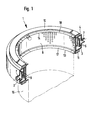
- Each calibration ring 1 consists of a ring 2 with a U-shaped profile, the legs 3, 4 of which form the flanks of an annular channel 5, which is closed towards the inside by a cylindrical sheet-metal plate 6 with holes, which is provided on the end faces of the legs 3, 4 or in the end region of the leg between them.
- the cylindrical ring-shaped web part of the profiled ring 2 is provided at regular intervals with a plurality of connecting pieces 7 for supplying cooling air. Cooling air is blown into the annular duct 5 through these connecting pieces 7. The cooling air is distributed in the annular duct 5 by air baffles 9 mounted in a suitable manner such that it emerges evenly from the sieve holes of the cylindrical sheet 6.
- Iris diaphragms 10, 11 are screwed onto the lower and upper legs 3, 4 of the profiled ring 2, which narrow the passage cross section through their end edges 13, 14.
- the iris diaphragms 10, 11 are of a commercial type and are therefore not described in detail.
- the passage cross sections delimited by the iris diaphragms 10, 11 can be changed continuously and thus adapted to the desired diameter of the tubular film 15.
- the cooling air blown in through the air connections 7 passes through the sieve openings into an annular space which is formed by the cylindrical sieve plate 6 and the lips 17, 18 of the iris diaphragms 10, 11.
- the cooling air emerges from this annular space to form a support cushion over the edges 13, 14 of the lips 17, 18 of the iris diaphragms and supports the film tube 15.
- the cooling air squeezes itself between the edges 13, 14 and the narrow gap forming the film tube and thus prevents the film tube from contacting the calibration rings 1 while calibrating the film tube.
Abstract
Description
Die Erfindung betrifft eine Vorrichtung zum Abstützen und Kalibrieren von Folienschläuchen aus thermoplastischem Kunststoff mit den Folienschlauch von außen umschließenden ringförmigen Stützelementen.The invention relates to a device for supporting and calibrating film tubes made of thermoplastic material with annular support elements surrounding the film tube from the outside.
Bei einer aus der DE-PS 20 04 881 bekannten Vorrichtung dieser Art bestehen die Stützelemente aus einzelnen gekrümmten stangenförmigen Stützsegmenten, die zur Verminderung der Reibung mit dem zu kalibrierenden Folienschlauch mit einem drehbaren Belag, üblicherweise Teflonröllchen, versehen sind. Bei hohen Abzugsgeschwindigkeiten und entsprechend großen Kühlluftmengen können jedoch aufgrund der Berührung zwischen den Teflonröllchen oder dergleichen und dem Folienschlauch Markierungen auf diesem entstehen. Derartige Markierungen können bei niedrigeren Abzugsgeschwindigkeiten vermieden werden, weil die mit Röllchen besetzten Stützsegmente dann unmittelbar oberhalb der Frostlinie angeordnet werden können. Bei hohen Abzugsgeschwindigkeiten läßt sich die Lage der Frostlinie nicht mehr genügend genau bestimmen, so daß sich sodann eine sogenannte Frostzone ausbildet, die über den Bereich der Stützsegmente hinausreicht.In a device of this type known from DE-PS 20 04 881, the support elements consist of individual curved rod-shaped support segments which are provided with a rotatable coating, usually Teflon rolls, to reduce the friction with the film tube to be calibrated. At high take-off speeds and correspondingly large amounts of cooling air, however, due to the contact between the Teflon rolls or the like and the film tube, markings can be made on it arise. Such markings can be avoided at lower take-off speeds because the support segments covered with rollers can then be arranged directly above the frost line. At high take-off speeds, the position of the frost line can no longer be determined with sufficient accuracy, so that a so-called frost zone then forms which extends beyond the area of the support segments.
Aus dem frisch extrudierten Folienschlauch dampfen wachsartige Bestandteile aus, die sich teilweise auf den die Röllchenachsen bildenden Stützsegmenten absetzen, so daß die einzelnen Röllchen nur gegen einen sich erhöhenden Widerstand drehbar sind. Da die Röllchen durch Mitnahme von dem Folienschlauch angetrieben sind, können bei hohen Abzugsgeschwindigkeiten sogenannte Pumpbewegungen des Folienschlauches angeregt werden, die sich aus den unterschiedlichen Reibungswiderständen der einzelnen Röllchen ergeben. Dies hat insgesamt eine schlechtere Regelmöglichkeit sowie eine schlechtere Oberflächenstruktur der Folie zur Folge.Wax-like components evaporate from the freshly extruded film tube, some of which settle on the support segments forming the roller axes, so that the individual rollers can only be rotated against increasing resistance. Since the rolls are driven by the film tube, so-called pumping movements of the film tube can be stimulated at high take-off speeds, which result from the different frictional resistances of the individual rolls. Overall, this results in poorer control options and a poorer surface structure of the film.
Aufgabe der Erfindung ist es daher, zur Vermeidung von Rückwirkungen auf die Schlauchfolie eine diese nicht berührende Abstütz- und Kalibriervorrichtung der eingangs angegebenen Art zu schaffen.It is therefore an object of the invention to provide a support and calibration device of the type specified at the outset that does not touch the tubular film in order to avoid any effects on it.
Erfindungsgemäß wird diese Aufgabe dadurch gelöst, daß die Stützelemente aus U-förmigen, mit nach innen offenen Ringkanälen versehenen Ringen bestehen, die Anschlüsse zum Zuführen von Kühlluft aufweisen, und daß der Durchmesser der inneren Ränder der seitlich den Ringkanal begrenzenden Flanken der Ringe dem zu kalibrierenden Durchmesser des Folienschlauches angepaßt ist.According to the invention, this object is achieved in that the support elements consist of U-shaped rings provided with inwardly open ring channels, which have connections for supplying cooling air, and in that the diameter of the inner edges of the flanks of the rings laterally delimiting the ring channel is to be calibrated Diameter of the film tube is adjusted.
In den bzw. die Ringkanäle wird eine derartige Luftmenge eingeblasen, daß die über die inneren Ränder der seitlichen Flanken abströmende Luft ein den abgezogenen Folienschlauch abstützendes Polster bildet. Dadurch ist sichergestellt, daß der abgezogene Folienschlauch mit den kalibrierenden Ringen nicht in Berührung kommt. Die zur Bildung der Stützpolster eingeblasene Luft hat zusätzlich den Vorteil, daß der Folienschlauch weiter abgekühlt wird.A quantity of air is blown into the ring channel (s) such that the air flowing over the inner edges of the side flanks forms a cushion that supports the pulled-off film tube. This ensures that the deducted Foil tube does not come into contact with the calibrating rings. The air blown in to form the support pads has the additional advantage that the film tube is cooled further.
Es ist wünschenswert, die kalibrierenden Stützelemente auf unterschiedliche Folienschlauchdurchmesser einstellen zu können. Nach einer erfinderischen Weiterbildung ist daher vorgesehen, daß die den Ringkanal begrenzenden seitlichen Flanken mit Irisblenden verbunden sind, die in einstellbarer Weise den Durchtrittsquerschnitt der Flanken verengen. Derartige Irisblenden sind bekannt und können im Handel erworben werden, so daß diese hier nicht näher beschrieben werden.It is desirable to be able to adjust the calibrating support elements to different film tube diameters. According to an inventive development, it is therefore provided that the side flanks delimiting the ring channel are connected with iris diaphragms which adjustably narrow the passage cross section of the flanks. Such iris diaphragms are known and can be purchased commercially, so that they are not described in more detail here.
Ein über den Umfang der Flanken gleichmäßiges Stützpolster aus Blasluft wird erreicht, wenn der Luftdruck über den Umfang des Ringkanals möglichst gleich ist. In weiterer Ausgestaltung der Erfindung ist der Ringkanal daher durch ein siebartig gelochtes Blech in Form eines zylindrischen Ringes geschlossen, das im Endbereich der Flanken zwischen diesen angeordnet ist. Weiterhin können in dem Ringkanal zur Vergleichmäßigung der Luftströmung und des Luftdrucks Prall- und/oder Leitbleche angeordnet sein.A support cushion made of blown air that is uniform over the circumference of the flanks is achieved if the air pressure over the circumference of the ring channel is as equal as possible. In a further embodiment of the invention, the ring channel is therefore closed by a perforated plate in the form of a cylindrical ring which is arranged in the end region of the flanks between them. In addition, baffle plates and / or baffles can be arranged in the ring channel in order to equalize the air flow and the air pressure.
Zweckmäßigerweise sind im Aufweitungsbereich bzw. in dem aufgeweiteten Bereich des Folienschlauches mehrere Ringe im Abstand voneinander übereinander angeordnet.Expediently, a plurality of rings are arranged at a distance from one another in the expansion area or in the expanded area of the film tube.
Ein Ausführungsbeispiel der Erfindung wird nachstehend anhand der Zeichnung näher erläutert. In dieser zeigtAn embodiment of the invention is explained below with reference to the drawing. In this shows
- Fig. 1 eine perspektivische Ansicht eines Axialschnit eines Kalibrierringes undFig. 1 is a perspective view of an axial section of a calibration ring and
- Fig. 2 einen Axialschnitt durch vier übereinander angeordnete Kalibrierringe.Fig. 2 shows an axial section through four calibration rings arranged one above the other.
Jeder Kalibrierring 1 besteht aus einem Ring 2 mit U-förmigem Profil, dessen Schenkel 3, 4 die Flanken eines Ringkanals 5 bilden, der nach innen hin durch ein siebartig mit Löchern versehenes zylinderringförmiges Blech 6 geschlossen ist, das an den Stirnseiten der Schenkel 3, 4 oder im Endbereich der Schenkel zwischen diesen befestigt ist. Das zylinderringförmige Stegteil des profilierten Ringes 2 ist in gleichmäßigen Abständen mit mehreren Anschlußstutzen 7 zur Zuführung von Kühlluft versehen. Durch diese Anschlußstutzen 7 wird Kühlluft in den Ringkanal 5 eingeblasen. Die Kühlluft wird in dem Ringkanal 5 durch in geeigneter Weise angebrachte Luftleitbleche 9 derart verteilt, daß sie gleichmäßig aus den Sieblöchern des zylinderringförmigen Bleches 6 austritt.Each
Auf die unteren und oberen Schenkel 3, 4 des profilierten Rings 2 sind Irisblenden 10, 11 aufgeschraubt, die durch ihre Stirnkanten 13, 14 den Durchtrittsquerschnitt verengen. Die Irisblenden 10, 11 sind handelsüblicher Art und werden daher nicht näher beschrieben. Die durch die Irisblenden 10, 11 begrenzten Durchtrittsquerschnitte lassen sich stufenlos ändern und somit dem gewünschten Durchmesser der Schlauchfolie 15 anpassen.
Die durch die Luftanschlüsse 7 eingeblasene Kühlluft tritt durch die Sieböffnungen in einen Ringraum, der durch das zylinderringförmige Siebblech 6 und die Lippen 17, 18 der Irisblenden 10, 11 gebildet wird. Aus diesem Ringraum tritt die Kühlluft unter Bildung eines Stützpolsters über die Kanten 13, 14 der Lippen 17, 18 der Irisblenden aus und stützt den Folienschlauch 15 ab. Die Kühlluft quetscht sich gleichsam durch sich zwischen den Kanten 13, 14 und dem Folienschlauch ausbildende schmale Spalte hindurch und verhindert so unter Kalibrierung des Folienschlauches deren Berührung mit den Kalibrierringen 1.The cooling air blown in through the
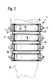
Bei dem Ausführungsbeispiel nach Fig. 2 sind vier Kalibrierringe der anhand der Fig. 1 erläuterten Art im Abstand übereinander angeordnet und durch Stehbolzen 19 miteinander in der Weise verbunden, daß zwischen den einzelnen Kalibrierringen ausreichende Spalte zum Abströmen der Kühl- und Stützluft gebildet sind.In the embodiment according to FIG. 2, four calibration rings of the type explained with reference to FIG. 1 are arranged one above the other at a distance and are connected to one another by
Claims (5)
Applications Claiming Priority (2)
| Application Number | Priority Date | Filing Date | Title |
|---|---|---|---|
| DE19833323817 DE3323817A1 (en) | 1983-07-01 | 1983-07-01 | DEVICE FOR SUPPORTING AND CALIBRATING FILM TUBES MADE OF THERMOPLASTIC PLASTIC |
| DE3323817 | 1983-07-01 |
Publications (1)
| Publication Number | Publication Date |
|---|---|
| EP0143154A1 true EP0143154A1 (en) | 1985-06-05 |
Family
ID=6202939
Family Applications (1)
| Application Number | Title | Priority Date | Filing Date |
|---|---|---|---|
| EP84106276A Withdrawn EP0143154A1 (en) | 1983-07-01 | 1984-06-01 | Apparatus for supporting and calibrating tubular films of thermoplastics |
Country Status (4)
| Country | Link |
|---|---|
| EP (1) | EP0143154A1 (en) |
| JP (1) | JPS6036124A (en) |
| DE (1) | DE3323817A1 (en) |
| ES (1) | ES289091Y (en) |
Cited By (2)
| Publication number | Priority date | Publication date | Assignee | Title |
|---|---|---|---|---|
| EP2801467A1 (en) | 2013-05-08 | 2014-11-12 | Kdesign GmbH | Calibration device for calibrating an extruded tubular film |
| WO2023138251A1 (en) * | 2022-01-20 | 2023-07-27 | 中国科学院微电子研究所 | Photolithography device, gas bath apparatus and gas bath generator thereof |
Families Citing this family (3)
| Publication number | Priority date | Publication date | Assignee | Title |
|---|---|---|---|---|
| US5128076A (en) * | 1991-03-21 | 1992-07-07 | Minnesota Mining And Manufacturing Company | Apparatus and method for producing an elongate strip of material |
| US5124094A (en) * | 1991-03-21 | 1992-06-23 | Minnesota Mining And Manufacturing Company | Apparatus and method for constraining a rotating tube of material |
| DE102004031366B4 (en) * | 2004-03-04 | 2014-09-04 | Windmöller & Hölscher Kg | blown film extrusion |
Citations (7)
| Publication number | Priority date | Publication date | Assignee | Title |
|---|---|---|---|---|
| DE1196850B (en) * | 1962-10-12 | 1965-07-15 | Basf Ag | Process and device for the production of highly transparent foils from thermoplastics |
| US3507006A (en) * | 1967-06-26 | 1970-04-21 | Shell Oil Co | Apparatus for producing thermoplastic film |
| DE2340398A1 (en) * | 1972-08-09 | 1974-02-21 | Ici Ltd | METHOD AND DEVICE FOR STABILIZING THE LOCATION OF A TUBE FILM |
| DE2510804A1 (en) * | 1974-05-06 | 1975-11-20 | Mobil Oil Corp | DEVICE FOR THE PRODUCTION OF EXTRUDED TUBULAR THERMOPLASTIC PLASTIC FILMS |
| DE2801406A1 (en) * | 1977-02-09 | 1978-08-10 | Mobil Oil Corp | DEVICE FOR THE PRODUCTION OF A TUBE-SHAPED FILM FROM THERMOPLASTIC PLASTIC |
| EP0077661A2 (en) * | 1981-10-16 | 1983-04-27 | Nippon Unicar Company Limited | Process and apparatus for forming a plastics film |
| JPS5881128A (en) * | 1981-11-09 | 1983-05-16 | Mitsui Petrochem Ind Ltd | Manufacture of inflation film and apparatus therefor |
-
1983
- 1983-07-01 DE DE19833323817 patent/DE3323817A1/en not_active Withdrawn
-
1984
- 1984-06-01 EP EP84106276A patent/EP0143154A1/en not_active Withdrawn
- 1984-06-29 JP JP59135033A patent/JPS6036124A/en active Pending
- 1984-06-29 ES ES1984289091U patent/ES289091Y/en not_active Expired
Patent Citations (8)
| Publication number | Priority date | Publication date | Assignee | Title |
|---|---|---|---|---|
| DE1196850B (en) * | 1962-10-12 | 1965-07-15 | Basf Ag | Process and device for the production of highly transparent foils from thermoplastics |
| US3507006A (en) * | 1967-06-26 | 1970-04-21 | Shell Oil Co | Apparatus for producing thermoplastic film |
| DE1778959B1 (en) * | 1967-06-26 | 1971-10-14 | Shell Int Research | DEVICE FOR COOLING A TUBE FILM MADE FROM THERMOPLASTIC PLASTIC, PRODUCED BY EXTRUSION |
| DE2340398A1 (en) * | 1972-08-09 | 1974-02-21 | Ici Ltd | METHOD AND DEVICE FOR STABILIZING THE LOCATION OF A TUBE FILM |
| DE2510804A1 (en) * | 1974-05-06 | 1975-11-20 | Mobil Oil Corp | DEVICE FOR THE PRODUCTION OF EXTRUDED TUBULAR THERMOPLASTIC PLASTIC FILMS |
| DE2801406A1 (en) * | 1977-02-09 | 1978-08-10 | Mobil Oil Corp | DEVICE FOR THE PRODUCTION OF A TUBE-SHAPED FILM FROM THERMOPLASTIC PLASTIC |
| EP0077661A2 (en) * | 1981-10-16 | 1983-04-27 | Nippon Unicar Company Limited | Process and apparatus for forming a plastics film |
| JPS5881128A (en) * | 1981-11-09 | 1983-05-16 | Mitsui Petrochem Ind Ltd | Manufacture of inflation film and apparatus therefor |
Cited By (3)
| Publication number | Priority date | Publication date | Assignee | Title |
|---|---|---|---|---|
| EP2801467A1 (en) | 2013-05-08 | 2014-11-12 | Kdesign GmbH | Calibration device for calibrating an extruded tubular film |
| US9457526B2 (en) | 2013-05-08 | 2016-10-04 | Kdesign Gmbh | Calibration device for calibrating an extruded film tube |
| WO2023138251A1 (en) * | 2022-01-20 | 2023-07-27 | 中国科学院微电子研究所 | Photolithography device, gas bath apparatus and gas bath generator thereof |
Also Published As
| Publication number | Publication date |
|---|---|
| JPS6036124A (en) | 1985-02-25 |
| ES289091U (en) | 1986-02-16 |
| DE3323817A1 (en) | 1985-01-10 |
| ES289091Y (en) | 1986-10-01 |
Similar Documents
| Publication | Publication Date | Title |
|---|---|---|
| DE2459785C2 (en) | Internal cooling device for tubular plastic films, which is connected downstream of a blow head with an annular gap nozzle that can be connected to a screw extruder | |
| DE2004888A1 (en) | ||
| DE2757181A1 (en) | EQUIPMENT AND METHOD FOR MANUFACTURING FILMS | |
| DE2359975C3 (en) | Cooling device for tubular films | |
| DE2357138C3 (en) | After-cooling device for blown films made of thermoplastics | |
| DE2616197C3 (en) | Device for calibrating plastic products emerging from an extruder | |
| DE1504604A1 (en) | Spray nozzle for the production of tubular films | |
| DE2340398B2 (en) | Device for stabilizing the position of an inflated tubular film | |
| EP0143154A1 (en) | Apparatus for supporting and calibrating tubular films of thermoplastics | |
| DE102006044643A1 (en) | Support device for plastic tubes has shaped tube support itself supported by several support elements adjustable to required profile | |
| DE2032346B2 (en) | Cooling device for tubular plastic films produced by means of a blow head | |
| DE1144987B (en) | Device for the contactless guiding of running webs, especially coated, still wet paper webs | |
| EP0127565A2 (en) | Calibrating device at an extruder | |
| DE2639551C2 (en) | Device for blowing tubular films made of thermoplastic material | |
| EP1386719A1 (en) | Calibrating device for the maufacture of plastic films | |
| DE2004881A1 (en) | Calibrating cage for blown plastic tube | |
| DE3626834C2 (en) | ||
| DE3245605C2 (en) | ||
| DE4109385C2 (en) | ||
| DE4238868C2 (en) | Foil blowing device | |
| DE2941260A1 (en) | Extruder head for mfg. polymer hoses - includes telescopic die with adjustable conical inlet surrounding torpedo core | |
| DE4428212A1 (en) | Foil blowing head for the production of tubular foils from thermoplastic | |
| DE3707826A1 (en) | Device for air cooling blown films with sector-by-sector adjustment of the annular-die gap widths | |
| DE3329616A1 (en) | DEVICE FOR CONTINUOUS SHAPING OF POLYSTYRENE | |
| DE2904783A1 (en) | METHOD AND DEVICE FOR MANUFACTURING A DRAIN |
Legal Events
| Date | Code | Title | Description |
|---|---|---|---|
| PUAI | Public reference made under article 153(3) epc to a published international application that has entered the european phase |
Free format text: ORIGINAL CODE: 0009012 |
|
| AK | Designated contracting states |
Designated state(s): AT CH FR GB IT LI |
|
| 17P | Request for examination filed |
Effective date: 19850705 |
|
| 17Q | First examination report despatched |
Effective date: 19860227 |
|
| STAA | Information on the status of an ep patent application or granted ep patent |
Free format text: STATUS: THE APPLICATION HAS BEEN WITHDRAWN |
|
| 18W | Application withdrawn |
Withdrawal date: 19860524 |
|
| RIN1 | Information on inventor provided before grant (corrected) |
Inventor name: DELLBRUEGGE, HERBERT |