EP0143012A1 - Installation to determine the spatial coordonates of points of a work piece - Google Patents
Installation to determine the spatial coordonates of points of a work piece Download PDFInfo
- Publication number
- EP0143012A1 EP0143012A1 EP84401741A EP84401741A EP0143012A1 EP 0143012 A1 EP0143012 A1 EP 0143012A1 EP 84401741 A EP84401741 A EP 84401741A EP 84401741 A EP84401741 A EP 84401741A EP 0143012 A1 EP0143012 A1 EP 0143012A1
- Authority
- EP
- European Patent Office
- Prior art keywords
- head
- laser beam
- rotor
- plane
- point
- Prior art date
- Legal status (The legal status is an assumption and is not a legal conclusion. Google has not performed a legal analysis and makes no representation as to the accuracy of the status listed.)
- Granted
Links
Images

Classifications
-
- B—PERFORMING OPERATIONS; TRANSPORTING
- B23—MACHINE TOOLS; METAL-WORKING NOT OTHERWISE PROVIDED FOR
- B23K—SOLDERING OR UNSOLDERING; WELDING; CLADDING OR PLATING BY SOLDERING OR WELDING; CUTTING BY APPLYING HEAT LOCALLY, e.g. FLAME CUTTING; WORKING BY LASER BEAM
- B23K26/00—Working by laser beam, e.g. welding, cutting or boring
- B23K26/02—Positioning or observing the workpiece, e.g. with respect to the point of impact; Aligning, aiming or focusing the laser beam
- B23K26/04—Automatically aligning, aiming or focusing the laser beam, e.g. using the back-scattered light
-
- B—PERFORMING OPERATIONS; TRANSPORTING
- B25—HAND TOOLS; PORTABLE POWER-DRIVEN TOOLS; MANIPULATORS
- B25J—MANIPULATORS; CHAMBERS PROVIDED WITH MANIPULATION DEVICES
- B25J9/00—Programme-controlled manipulators
- B25J9/16—Programme controls
- B25J9/1679—Programme controls characterised by the tasks executed
- B25J9/1692—Calibration of manipulator
-
- G—PHYSICS
- G01—MEASURING; TESTING
- G01B—MEASURING LENGTH, THICKNESS OR SIMILAR LINEAR DIMENSIONS; MEASURING ANGLES; MEASURING AREAS; MEASURING IRREGULARITIES OF SURFACES OR CONTOURS
- G01B11/00—Measuring arrangements characterised by the use of optical techniques
- G01B11/002—Measuring arrangements characterised by the use of optical techniques for measuring two or more coordinates
- G01B11/005—Measuring arrangements characterised by the use of optical techniques for measuring two or more coordinates coordinate measuring machines
- G01B11/007—Measuring arrangements characterised by the use of optical techniques for measuring two or more coordinates coordinate measuring machines feeler heads therefor
-
- G—PHYSICS
- G01—MEASURING; TESTING
- G01S—RADIO DIRECTION-FINDING; RADIO NAVIGATION; DETERMINING DISTANCE OR VELOCITY BY USE OF RADIO WAVES; LOCATING OR PRESENCE-DETECTING BY USE OF THE REFLECTION OR RERADIATION OF RADIO WAVES; ANALOGOUS ARRANGEMENTS USING OTHER WAVES
- G01S17/00—Systems using the reflection or reradiation of electromagnetic waves other than radio waves, e.g. lidar systems
- G01S17/87—Combinations of systems using electromagnetic waves other than radio waves
-
- G—PHYSICS
- G01—MEASURING; TESTING
- G01S—RADIO DIRECTION-FINDING; RADIO NAVIGATION; DETERMINING DISTANCE OR VELOCITY BY USE OF RADIO WAVES; LOCATING OR PRESENCE-DETECTING BY USE OF THE REFLECTION OR RERADIATION OF RADIO WAVES; ANALOGOUS ARRANGEMENTS USING OTHER WAVES
- G01S5/00—Position-fixing by co-ordinating two or more direction or position line determinations; Position-fixing by co-ordinating two or more distance determinations
- G01S5/16—Position-fixing by co-ordinating two or more direction or position line determinations; Position-fixing by co-ordinating two or more distance determinations using electromagnetic waves other than radio waves
Abstract
a) Installation pour la détermination des coordonnées spatiales d'un point (P) d'une pièce (7) notamment pour le contrôle d'un outillage tel qu'un outillage de soudage de carrosserie de véhicule automobile. b) Installation caractérisée en ce qu'elle comporte une tête (11) mobile dans un plan (X-Y) produisant un signal fonction de la distance du point (P) par rapport au plan (X-Y), un rotor (13) sur la tête (11), ce rotor comportant un moyen projetant un faisceau laser tournant (214), au moins trois cibles fixes (Q, R, S) disposées dans le plan (X-Y) et dont les coordonnées dans ce plan sont connues, ces cibles étant susceptibles de produire en signal fonction de la position (Xp-Yp) de la tête (11) et donc du point de mesure (P) dans le plan (X-Y). c) L'invention s'applique à une installation pour la détermination des coordonnées spatiales d'un point.a) Installation for determining the spatial coordinates of a point (P) of a part (7), in particular for controlling a tool such as a tool for welding automobile bodywork. b) Installation characterized in that it comprises a head (11) movable in a plane (XY) producing a signal as a function of the distance from point (P) relative to the plane (XY), a rotor (13) on the head (11), this rotor comprising a means projecting a rotating laser beam (214), at least three fixed targets (Q, R, S) arranged in the plane (XY) and whose coordinates in this plane are known, these targets being capable of producing as a signal as a function of the position (Xp-Yp) of the head (11) and therefore of the measurement point (P) in the plane (XY). c) The invention applies to an installation for determining the spatial coordinates of a point.
Description
"Installation pour la détermination des coordonnées spatiales d'un point d'une pièce, notamment pour le contrôle d'un outillage tel qu'un outillage de soudage de carrosserie de véhicule automobile"."Installation for the determination of the spatial coordinates of a point of a part, in particular for the control of a tool such as a tool for welding automobile bodywork".
L'invention concerne une installation pour la détermination des coordonnées spatiales d'un point d'une pièce, notamment pour le contrôle d'un outillage tel qu'un outillage de soudage de carrosserie de véhicule automobile.The invention relates to an installation for determining the spatial coordinates of a point of a part, in particular for controlling a tool such as a tool for welding the body of a motor vehicle.
Les installations de soudage de pièces de carrosserie automobile comportent un outillage destiné à assurer le positionnement relatif et le serrage des pièces de carrosserie que l'on doit souder les unes aux autres. Cet outillage de positionnement et de serrage comporte ainsi plusieurs pièces d'appui dont le profil est la copie exacte, ou contre-forme, de la partie de surface correspondant à la pièce de la carrosserie à assembler. Ces surfaces d'appui doivent, avant l'utilisation de l'installation, être positionnées rigoureusement sur la platine de support de l'outillage les unes par rapport aux autres et par rapport aux organes de serrage et de soudage, afin que les pièces à souder s'adaptent parfaitement, par leur forme, sur ces surfaces, afin que ces pièces soient correctement positionnées et serrées les unes par rapport aux autres et afin que le soudage des pièces s'effectue à des endroits précis.Welding installations for automobile body parts include a tool intended to ensure the relative positioning and tightening of the body parts which have to be welded together. This positioning and tightening tool thus comprises several support parts whose profile is the exact copy, or counter-form, of the surface part corresponding to the part of the body to be assembled. These support surfaces must, before using the installation, be rigorously positioned on the tool support plate with respect to each other and with respect to the clamping and welding members, so that the parts to be weld fit perfectly, by their shape, on these surfaces, so that these parts are correctly positioned and clamped with respect to each other and so that the welding of the parts takes place at precise locations.
Ces réglages préalables sont longs et délicats, et s'effectuent manuellement, de manière empirique par approche successive en utilisant des structures spécifiques ajustées sur des moules des pièces à assembler et permettent de régler la position de chacune des surfaces d'appui par rapport à des points de référence.These preliminary adjustments are long and delicate, and are carried out manually, empirically by successive approach using specific structures adjusted on molds of the parts to be assembled and allow the position of each of the bearing surfaces to be adjusted relative to reference points.
On connaît, par ailleurs, des capteurs dénommés d'une manière générale capteurs de position à faisceau laser qui se composent (voir figure 1) d'un générateur de faisceau laser 1 et d'un capteur 2 qui reçoit le faisceau laser 3 issu du générateur après réflexion sur la pièce 4 dont on désire mesurer la distance par rapport à une surface de référence.Also known are sensors generally referred to as laser beam position sensors which are composed (see FIG. 1) of a
Le générateur 1 et le capteur 2 sont montés sur un bâti 5, lui-même fixé sur une platine 6 qui constitue une surface de référence, de manière que le faisceau laser 3 perpendiculaire à la platine 6 vienne frapper la pièce 4 au point de mesure 4. La position du faisceau laser réfléchi 31 est alors, après étalonnage de l'appareil, fonction de la distance du point 41 par rapport à la platine 6, c'est-à-dire par rapport à la surface de référence. Cette position du faisceau laser réfléchi 3 est détectée par le capteur 2 qui produit une information envoyée dans un compteur 21. Ce compteur affiche alors la distance du point 41.The
Un tel capteur de position à laser permet une bonne précision de mesure (inférieure au centième de millimètre) mais sa mise en oeuvre pour déterminer des coordonnées spatiales d'un point d'un outillage de soudage de carrosserie de véhicule automobile n'est pas envisageable, car cela nécessite la mise en oeuvre d'une platine de référence qui est incompatible, en raison de son encombrement, avec un outillage de soudage de carrosserie. En outre, une telle installation entraînerait des manipulations longues, car elle nécessiterait la fixation successive du bâti 5 sur la platine au droit de chaque point de mesure et, en outre, il serait nécessaire de déterminer pour chaque point de mesure les coordonnées exactes de la fixation du capteur de position sur la platine.Such a laser position sensor allows good measurement accuracy (less than a hundredth of a millimeter), but its use for determining the spatial coordinates of a point of a tool for welding bodywork of a motor vehicle is not possible. , because this requires the use of a reference plate which is incompatible, due to its size, with body welding tools. In addition, such an installation would involve long manipulations, because it would require the successive fixing of the
La présente invention a pour but de permettre une détermination rapide et précise des coordonnées spatiales d'un nombre important de points et particulièrement de points d'un outillage de soudage de carrosserie de véhicule automobile en supprimant, pour chaque point de mesure, la nécessité d'une fixation mécanique particulière de l'appareil de mesure, et en supprimant donc, d'une part les moyens de fixation de l'appareil de mesure et, d'autre part, l'obligation de déterminer, pour chaque mesure, les coordonnées du point de fixation de l'appareil.The object of the present invention is to allow rapid and precise determination of the spatial coordinates of a large number of points and in particular points of a tool for welding bodywork of a motor vehicle by eliminating, for each measurement point, the need for '' a particular mechanical fixing of the measuring device, and thus eliminating, on the one hand the means of fixing the measuring device and, on the other hand, the obligation to determine, for each measurement, the coordinates the attachment point of the device.
La présente invention a également pour but de permettre la comparaison directe des coordonnées des points de mesure déterminées par l'installation avec les coordonnées du point théorique correspondant fournies par l'expression numérique de la forme de la ou des pièces de carrosseries à positionner.The present invention also aims to allow direct comparison of the coordinates of the measurement points determined by the installation with the coordinates of the corresponding theoretical point provided by the numerical expression of the shape of the bodywork part (s) to be positioned.
L'installation de l'invention est caractérisée en ce qu'elle comporte une tête mobile dans un plan, un capteur de position à faisceau laser sur la tête, ce capteur de position comportant un moyen projetant un faisceau laser sur le point de la pièce dont on désire mesurer les coordonnées et un moyen capteur pour recevoir le faisceau laser réfléchi par la pièce en ce point afin de produire un signal fonction de la distance du point par rapport au plan, un rotor sur la tête, l'axe de rotation de ce rotor étant perpendiculaire au plan, ce rotor comportant un moyen projetant un faisceau laser tournant, au moins trois cibles fixes disposées dans le plan et dont les coordonnées dans ce plan sont connues, ces cibles étant susceptibles de produire un signal fonction de la position de la tête et donc du point de mesure dans le plan, un moyen calculateur pour recevoir les informations des deux moyens capteurs et déterminer les coordonnées spatiales du point de mesure, un moyen d'affichage pour afficher ces coordonnées.The installation of the invention is characterized in that it comprises a head movable in a plane, a laser beam position sensor on the head, this position sensor comprising means projecting a laser beam at the point of the workpiece whose coordinates are to be measured and a sensor means for receiving the laser beam reflected by the part at this point in order to produce a signal as a function of the distance from the point relative to the plane, a rotor on the head, the axis of rotation of this rotor being perpendicular to the plane, this rotor comprising a means projecting a rotating laser beam, at least three fixed targets arranged in the plane and whose coordinates in this plane are known, these targets being capable of producing a signal as a function of the position of the head and therefore from the measurement point in the plane, calculating means for receiving information from the two sensor means and determining the spatial coordinates of the measurement point, display means for displaying these coordinates.
Suivant une autre caractéristique de l'invention, les cibles sont des cibles passives et réfléchissent le faisceau laser projeté par le rotor de la tête vers un moyen capteur prévu sur le rotor et produisent un signal fonction de la position de la tête.According to another characteristic of the invention, the targets are passive targets and reflect the laser beam projected by the rotor of the head towards a sensor means provided on the rotor and produce a signal as a function of the position of the head.
Suivant une autre caractéristique de l'invention, l'axe de rotation du rotor de la tête est confondu avec l'axe du faisceau laser incident produit par le capteur de position de cette tête.According to another characteristic of the invention, the axis of rotation of the rotor of the head is coincident with the axis of the incident laser beam produced by the position sensor of this head.
Suivant une autre caractéristique de l'invention, la tête est mobile par translation dans le plan par pivotement sur un bras lui-même pivotant sur un pied fixe.According to another characteristic of the invention, the head is movable by translation in the plane by pivoting on an arm itself pivoting on a fixed foot.
L'invention est représentée à titre d'exemple non limitatif sur les dessins ci-joints, dans lesquels :
- - la figure 1 est une vue latérale schématique d'un capteur de position à laser de type connu,
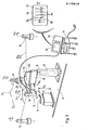
- - la figure 2 est une vue en perspective d'un mode de réalisation de l'ensemble de l'installation conforme à l'invention,
- - la figure 3 est une coupe axiale verticale de la` tête de mesure de l'installation de la figure 2.
- FIG. 1 is a schematic side view of a laser position sensor of known type,
- FIG. 2 is a perspective view of an embodiment of the entire installation in accordance with the invention,
- - Figure 3 is a vertical axial section of the measuring head of the installation of Figure 2.
Suivant la figure 2, l'installation est destinée au contrôle d'un outillage de soudage de carrosserie de véhicule automobile, pour lequel une seule pièce d'appui 7 a été représentée, afin de simplifier le dessin. Egalement, sur ce dessin, les appareils de soudage et les organes de serrage qui sont connus en eux-mêmes n'ont pas été représentés afin de ne pas le compliquer.According to Figure 2, the installation is intended for controlling a tool for welding the body of a motor vehicle, for which a
La pièce d'appui 7 présente une surface 71 dont la forme correspond à celle d'un élément de surface d'une des pièces de carrosserie que l'on doit souder, cette pièce 7 devant donc être positionnée sur la platine de support 8 afin que chaque point de la surface 71 occupe une position spatiale déterminée par rapport aux autres pièces 7 et que les parties de carrosserie s'adaptent correctement sur l'ensemble de ces pièces.The
Sur la platine horizontale 8 est fixé un pied vertical 9 pourvu à son extrémité supérieure d'un bras 10 pivotant dans un plan horizontal sur un axe vertical 91. Ce bras 10 reçoit également à pivotement sur un axe vertical 101 une tête de mesure 11, cette tête de mesure pouvant ainsi se déplacer dans un plan horizontal X-Y afin de pouvoir être amené rapidement par translation à la verticale des points de mesure de l'ensemble des pièces d'appui, tel que le point P de la pièce 7.On the horizontal plate 8 is fixed a
Cette installation comporte également des cibles Q, R, S qui sont fixées sur la platine 8 de manière à être situées dans le plan X-Y, les coordonnées W1, Y1, X2, Y2 et X3, Y3 de ces cibles sur la platine 8 prise comme référence étant ainsi connues.This installation also includes targets Q, R, S which are fixed on the plate 8 so as to be located in the plane XY, the coordinates W 1 , Y 1 , X 2 , Y 2 and X 3 , Y 3 of these targets on the plate 8 taken as a reference being thus known.
Ces cibles seront éloignées des pièces 7 et de l'ensemble de l'outillage assurant le positionnement, le serrage et le soudage des pièces afin de ne pas gêner leur mise en place et leur fonctionnement ultérieur.These targets will be distant from the
La tête de mesure 11 comporte un boitier inférieur 12 pourvu d'un capteur de position à faisceau laser propre à déterminer, après étalonnage, la distance Zp du point de mesure P par rapport à la platine 8 ou par rapport à toute autre surface de référence. Au-dessus de ce boitier 12, est prévu un rotor 13 propre à déterminer, par triangulation, en coopérant avec les cibles Q, R, S, les coordonnées Xp, Yp de l'axe 111 de la tête 11, ces coordonnées étant également celles du point P dans ce plan.The
Les coordonnées X , Yp et Z déterminent ainsi la position spatiale du point P et elles sont comparées, par un ordinateur 14, avec les coordonnées théoriques de ce même point emmagasinées dans une mémoire, afin qu'un organe de visualisation 15 puisse permettre de repérer sur son écran 16 la différence entre les coordonnées mesurées et les coordonnées théoriques mises en mémoire dans l'ordinateur. Ces coordonnées théoriques seront de préférence établies par l'expression numérique de la forme de la pièce ou des pièces de carrosserie à traiter.The coordinates X, Y p and Z thus determine the spatial position of the point P and they are compared, by a
Ainsi, ce contrôle pourra être réalisé en visualisant sur l'écran 16 des points 171 correspondant chacun à la valeur mesurée Zp d'un point de mesure P de coordonnées Xp, Yp, Zp. On pourra ainsi obtenir par extrapolation une courbe 17 et en comparant la position de cette courbe 17 avec la courbe théorique 18 obtenue à partir des coordonnées théoriques mémorisées donnant la valeur théorique de Zt, de Z pour divers points 181 de coordonnées Xt, Yt et Z t.Thus, this control can be carried out by viewing on the
L'opérateur pourra alors contrôler le positionnement correct de la touche 7 en constatant la coinci- dence des courbes 17 et 18 et dans le cas contraire, il modifiera la position de la pièce 7 sur la platine 8 afin d'obtenir cette coïncidence. Il pourra également obtenir, de ces systèmes, les valeurs numériques des écarts entre les positions réelles mesurées et les positions théoriques.The operator will then be able to check the correct positioning of the
La tête de mesure 11 est alimentée par un faisceau laser 191 issu d'un générateur de faisceaux laser 19 disposé dans le pied 4, ce faisceau laser étant transporté jusqu'à la tête 11 par un câble à fibres optiques 20.The
Ce faisceau laser 191 vient tout d'abord frapper, à l'intérieur du boîtier 12, un séparateur 21 connu en lui-même et constitué, par exemple, par un miroir semi- transparent et un ensemble de lentilles et de prismes. Ce séparateur 21 disposé suivant l'axe 111 produit deux faisceaux laser émergeant opposés coaxiaux 211 et 212 qui sont projetés suivant l'axe 11 de la tête 11 parallèle à la direction Z, c'est-à-dire perpendiculaire au plan X-Y.This
Le faisceau 211 est mis en oeuvre dans un capteur de position à faisceau laser afin de déterminer, après étallonnage, la distance Z .The
A cet effet, le faisceau 211 vient frapper la surface 71 de la pièce 7 au point P et est réfléchi en 213 vers le capteur 22 dont l'information, fonction de Z est amenée vers l'ordinateur 14 et l'organe de visualisation 15.To this end, the
Le rotor 13 est monté à rotation sur le boîtier 12 coaxialement à l'axe 111 de la tête 11 et est à cet effet entraîné à partir du moteur 24 et par l'intermédiaire de l'ensemble d'engrenage 25.The
Ce rotor 13 comporte un miroir 26 ou similaire qui produit, à partir du faisceau laser 212 un faisceau 214 disposé dans le plan X-Y et entraîné en rotation dans ce plan du fait de la rotation du rotor 13. Ainsi, au cours de la rotation du rotor 13, le faisceau laser 214 vient successivement frapper et se réfléchir sur les surfaces réfléchissantes 27 des cibles Q, R, S, ces surfaces réfléchissantes étant constituées par des miroirs cylindriques dont l'axe est orienté suivant la direction Z.This
Ainsi, quelle que soit la position de la tête 11, le faisceau laser 214 réfléchi par les miroirs 27 suivant un faisceau 215 est reçu par un capteur 28 disposé à l'intérieur de la tète 13 et orienté parallèlement au faisceau 214.Thus, whatever the position of the
La mesure des coordonnées X , Y du point P est effectuée par triangulation par des mesures de type goniométrique. Ces coordonnées sont déterminées par la valeur des angles α et β dont le sommet est constitué par l'axe 111 de la tête 11 passant par le point P et dont les côtés sont délimités par les faisceaux laser 214 et 215 venant frapper et se réfléchir sur les cibles Q, R et R, S.The measurement of the coordinates X, Y of the point P is carried out by triangulation by measurements of the goniometric type. These coordinates are determined by the value of the angles α and β whose apex is formed by the
La mesure de ces angles est obtenue par le comptage d'impulsions fournies par l'action de la rotation de la tête sur un générateur 30 mécaniquement lié à cette rotation, chaque valeur angulaire de rotation correspondant à un nombre déterminé d'impulsions et permettant d'obtenir la précision de mesure cherchée. Pour chaque angle α et β le comptage des impulsions commence et finit par le passage du rayon laser sur l'une des cibles Q, R, S, ce passage étant enregistré lors de la réception par l'élément opto-électronique 29 de l'écho dudit rayon.The measurement of these angles is obtained by counting pulses supplied by the action of the rotation of the head on a
Les nombres d'impulsions Nα et Nβ enregistrés par le système sont traduits par l'ordinateur en coordonnées Xp et Yp de l'axe du système, à partir des couples X1, Y1, X2, Y2, X3, Y3 des coordonnées des cibles préalablement connues.The numbers of pulses N α and N β recorded by the system are translated by the computer into coordinates X p and Y p of the axis of the system, from the couples X 1 , Y 1 , X 2 , Y 2 , X 3 , Y 3 of the coordinates of the previously known targets.
Bien entendu, un fonctionnement correct de l'installation conforme à l'invention ne pourra être obtenu qu'après étalonnage, c'est-à-dire après avoir déterminé de manière précise les coordonnées X1, Y1, X2, Y2 et X3, Y3 des cibles Q, R, S par rapport à une référence et de préférence par rapport à la platine 8 et après avoir déterminé la position de la tête 11 par rapport à cette même référence 8 dans la direction Z.Of course, correct operation of the installation in accordance with the invention can only be obtained after calibration, that is to say after having precisely determined the coordinates X 1 , Y 1 , X 2 , Y2 and X3 , Y3 of the targets Q, R, S with respect to a reference and preferably with respect to the plate 8 and after having determined the position of the
Après ces réglages, il suffira de déplacer la tête 11 dans le.plan X-Y par pivotement de cette tête sur le bras 10 et du bras 10 sur le pied 9, afin de placer successivement la tête 11 à la verticale des divers points de mesure souhaités de l'ensemble des pièces 7.After these adjustments, it will suffice to move the
Afin de simplifier la présente description, il est indiqué que le miroir 26 produit un faisceau 211 qui tourne dans le plan X-Y contenant les cibles Q, R, S, ces cibles réfléchissant ce faisceau laser vers le capteur 28 du rotor. Il sera cependant compris que dans la pratique le miroir 26 et le capteur 28 pourront être décalés du plan contenant les cibles Q, R, S, le miroir, les cibles et le capteur étant dans ce cas inclinés de façon que dans tous les cas le faisceau laser tournant 214 projeté par le miroir vienne frapper ces cibles et le renvoie vers le capteur 28.In order to simplify the present description, it is indicated that the
Egalement, dans la présente description, les cibles Q, R, S sont des réflecteurs passifs, le passage du faisceau sur elles donnant lieu à un écho capté par l'élément opto-électronique 29.Also, in the present description, the targets Q, R, S are passive reflectors, the passage of the beam over them giving rise to an echo picked up by the opto-
Dans une seconde version du même dispositif, les cibles Q, R et S sont actives et comportent chacune un composant opto-électronique similaire à 28 et fournissant directement l'impulsion de passage pour le commencement ou l'arrêt du comptage angulaire.In a second version of the same device, the targets Q, R and S are active and each comprise an opto-electronic component similar to 28 and directly supplying the passage impulse for the start or stop of the angular counting.
Dans une autre version du même dispositif, les cibles Q, R et S sont également actives et fournissent lors du passage du rayon, outre l'impulsion de passage, une information sous forme analogique ou numérique relative à la hauteur de chaque cible par rapport à un niveau de référence lié au support de cible, cette hauteur étant celle à laquelle le faisceau agit sur une cible considérée. Dans ce cas, le système permettra de connaître, pour chaque couple X, Y, connu par avance, la coordonnée Z.In another version of the same device, the targets Q, R and S are also active and provide, during the passage of the ray, in addition to the passing pulse, information in analog or digital form relating to the height of each target relative to a reference level linked to the target support, this height being that at which the beam acts on a target considered. In this case, the system will make it possible to know, for each pair X, Y, known in advance, the coordinate Z.
La référence des mesures n'est plus alors constituée par le plan supérieur de la platine 8 mais par un plan défini par les trois points X1, Y1, Z1, X2, Y 2' Z 2' X 3' Y3, Z3 liés au dispositif et non à l'outillage.The measurement reference is then no longer constituted by the upper plane of the plate 8 but by a plane defined by the three points X 1 , Y 1 , Z 1 , X 2 , Y 2 ' Z 2' X 3 ' Y 3 , Z 3 linked to the device and not to the tool.
Claims (7)
Applications Claiming Priority (2)
| Application Number | Priority Date | Filing Date | Title |
|---|---|---|---|
| FR8314324A FR2551860B1 (en) | 1983-09-08 | 1983-09-08 | INSTALLATION FOR THE DETERMINATION OF SPATIAL COORDINATES OF A POINT OF A WORKPIECE, PARTICULARLY FOR THE CHECKING OF A TOOLS SUCH AS A WELDING TOOL FOR A VEHICLE BODY |
| FR8314324 | 1983-09-08 |
Publications (2)
| Publication Number | Publication Date |
|---|---|
| EP0143012A1 true EP0143012A1 (en) | 1985-05-29 |
| EP0143012B1 EP0143012B1 (en) | 1989-03-29 |
Family
ID=9292063
Family Applications (1)
| Application Number | Title | Priority Date | Filing Date |
|---|---|---|---|
| EP84401741A Expired EP0143012B1 (en) | 1983-09-08 | 1984-08-29 | Installation to determine the spatial coordonates of points of a work piece |
Country Status (7)
| Country | Link |
|---|---|
| US (1) | US4651283A (en) |
| EP (1) | EP0143012B1 (en) |
| JP (1) | JPS60149905A (en) |
| CA (1) | CA1228922A (en) |
| DE (1) | DE3477512D1 (en) |
| ES (1) | ES535700A0 (en) |
| FR (1) | FR2551860B1 (en) |
Cited By (8)
| Publication number | Priority date | Publication date | Assignee | Title |
|---|---|---|---|---|
| WO1991006826A1 (en) * | 1989-10-24 | 1991-05-16 | Lk Limited | Calibration of measuring apparatus |
| US5046851A (en) * | 1987-03-18 | 1991-09-10 | Davy Mckee (Poole) Limited | Position sensing method and apparatus |
| WO1993023764A1 (en) * | 1992-05-21 | 1993-11-25 | Vernon Gauging Systems Limited | Gauging apparatus |
| FR2696541A1 (en) * | 1992-10-01 | 1994-04-08 | Framatome Sa | Surveying interior of ductwork entering steam generator of nuclear reactor prior to cutting - using laser beam detector which is movable inside duct and adjacent spigot |
| FR2721395A1 (en) * | 1994-06-17 | 1995-12-22 | Homer Eaton | Method for locating a trihedron in space and device for implementing this method. |
| EP0754930A2 (en) * | 1995-07-20 | 1997-01-22 | Bayerische Motoren Werke Aktiengesellschaft, Patentabteilung AJ-3 | Device for scanning measurement surfaces |
| FR2764992A1 (en) * | 1997-06-24 | 1998-12-24 | Romain Granger | Three dimensional positional location mechanism for car body assembly |
| DE19945717A1 (en) * | 1999-09-23 | 2001-04-26 | Lehmann Maschb Gmbh | Method for non-contact measurement of position or geometry of large components or assemblies or to position manipulation units or tool machines; involves using moving and fixed laser distance sensors |
Families Citing this family (37)
| Publication number | Priority date | Publication date | Assignee | Title |
|---|---|---|---|---|
| US5374830A (en) * | 1984-10-12 | 1994-12-20 | Sensor Adaptive Machines, Inc. | Target based determination of robot and sensor alignment |
| US5267143A (en) * | 1984-10-12 | 1993-11-30 | Sensor Adaptive Machines, Incorporated | Vision assisted fixture construction |
| US4638143A (en) * | 1985-01-23 | 1987-01-20 | Gmf Robotics Corporation | Robot-laser system |
| US4897518A (en) * | 1987-03-06 | 1990-01-30 | Tocco, Inc. | Method of monitoring induction heating cycle |
| US4816633A (en) * | 1987-03-06 | 1989-03-28 | Tocco, Inc. | Method of monitoring induction heating cycle |
| US4841460A (en) * | 1987-09-08 | 1989-06-20 | Perceptron, Inc. | Method and apparatus for calibrating a non-contact gauging sensor with respect to an external coordinate system |
| US4880992A (en) * | 1987-10-08 | 1989-11-14 | Siemens Aktiengesellschaft | Non-contacting measuring system for precision characteristics, particularly of industrial robots |
| JP2542653B2 (en) * | 1987-12-10 | 1996-10-09 | ファナック株式会社 | Non-contact copying method |
| JPH0690042B2 (en) * | 1988-05-13 | 1994-11-14 | 本田技研工業株式会社 | Position control device for self-propelled vehicle |
| JPH0829726B2 (en) * | 1988-07-18 | 1996-03-27 | 日産自動車株式会社 | Assembly method of car body |
| US5181823A (en) * | 1989-10-27 | 1993-01-26 | Grumman Aerospace Corporation | Apparatus and method for producing a video display |
| JPH04189452A (en) * | 1990-11-20 | 1992-07-07 | Fanuc Ltd | Digitizing control device |
| FR2683036B1 (en) * | 1991-10-25 | 1995-04-07 | Sextant Avionique | METHOD AND DEVICE FOR DETERMINING THE ORIENTATION OF A SOLID. |
| WO1994014567A1 (en) * | 1992-12-18 | 1994-07-07 | Firebird Traders Ltd. | Process and apparatus for etching an image within a solid article |
| US5637244A (en) * | 1993-05-13 | 1997-06-10 | Podarok International, Inc. | Method and apparatus for creating an image by a pulsed laser beam inside a transparent material |
| US6078846A (en) * | 1996-02-06 | 2000-06-20 | Perceptron, Inc. | Calibration and compensation of robot-based gauging system |
| US5793483A (en) * | 1996-02-07 | 1998-08-11 | Visidyne, Inc. | Optical measurement system |
| US5974348A (en) * | 1996-12-13 | 1999-10-26 | Rocks; James K. | System and method for performing mobile robotic work operations |
| CA2265215C (en) * | 1998-04-02 | 2004-06-22 | Lincoln Global, Inc. | Welding monitoring system |
| FR2783318B1 (en) * | 1998-09-14 | 2000-12-01 | Laurent Rouard | NON-CONTACT DIMENSIONAL MEASUREMENT SYSTEM FOR AN OBJECT |
| SE512983C2 (en) * | 1998-10-13 | 2000-06-12 | Ericsson Telefon Ab L M | Procedure and apparatus for monitoring objects |
| US7800758B1 (en) * | 1999-07-23 | 2010-09-21 | Faro Laser Trackers, Llc | Laser-based coordinate measuring device and laser-based method for measuring coordinates |
| GB0008303D0 (en) * | 2000-04-06 | 2000-05-24 | British Aerospace | Measurement system and method |
| GB0008302D0 (en) * | 2000-04-06 | 2000-05-24 | British Aerospace | Assembly method |
| DE10048097A1 (en) * | 2000-09-28 | 2002-04-18 | Zeiss Carl | The coordinate |
| FR2814807B1 (en) * | 2000-10-04 | 2003-01-03 | Laurent Senee | DEVICE AND METHOD FOR DETERMINING SURFACE COORDINATES AND USES THEREOF |
| ITMI20011241A1 (en) * | 2001-06-13 | 2002-12-13 | Advanced Technologies S R L | METHOD FOR CALIBRATION AND CALIBRATION OF SENSORS IN AN ASSEMBLY STATION AND ASSEMBLY STATION |
| DE10246783A1 (en) * | 2002-10-08 | 2004-04-22 | Stotz-Feinmesstechnik Gmbh | Object-handling using robotic arms, determines arm position in relation to reference system laid down by associated location system |
| JP4216772B2 (en) * | 2004-06-17 | 2009-01-28 | 株式会社東芝 | Self-position identification device and self-position identification method |
| US9302345B2 (en) * | 2007-08-31 | 2016-04-05 | Caterpillar Inc. | Laser machining calibration method |
| DE102010032467A1 (en) * | 2010-07-28 | 2012-02-02 | Carl Zeiss Ag | Measurement system for measuring position of measured object i.e. automobile part in automobile manufacturing facility, has computing units linking coordinates of surface positions of measured objects with measuring head position |
| US8855404B2 (en) * | 2012-08-27 | 2014-10-07 | The Boeing Company | Methods and systems for inspecting a workpiece |
| CN103286440A (en) * | 2013-06-17 | 2013-09-11 | 沈阳飞机工业(集团)有限公司 | Fast positioning method of laser cutting part |
| US11167866B2 (en) * | 2018-06-22 | 2021-11-09 | Southwest Research Institute | Localization system and methods |
| WO2020019209A1 (en) * | 2018-07-25 | 2020-01-30 | 西门子(中国)有限公司 | Optical locator |
| CN109530944B (en) * | 2018-12-20 | 2021-05-11 | 中国航空制造技术研究院 | Laser cutting accurate positioning system and method for special-shaped cylindrical part |
| CN111381560B (en) * | 2020-04-30 | 2023-01-06 | 中国航发哈尔滨东安发动机有限公司 | Zero point compensation method and device for mechanical processing |
Citations (6)
| Publication number | Priority date | Publication date | Assignee | Title |
|---|---|---|---|---|
| GB1449050A (en) * | 1972-11-30 | 1976-09-08 | Univ Australian | Device for determining the location of orientation of an object in a designated environment |
| DE2605772A1 (en) * | 1976-02-13 | 1977-08-18 | Komeg Kontroll Technik Ingenie | Workpiece measuring probe system - uses point light sources with three degrees of freedom in controlled relation to sensing points |
| US4113388A (en) * | 1976-06-25 | 1978-09-12 | National Research Development Corporation | Optical apparatus for determining relative positioning of two members |
| US4209252A (en) * | 1978-07-03 | 1980-06-24 | Arditty Herve J | Optical probe assembly for detecting the position of an object surface and method |
| DE2911739A1 (en) * | 1979-03-26 | 1980-10-02 | Wilhelm Becker | Point planimeter with electro-optical distance measurement system - consisting of sources and receivers with controlled electric positioning from slide moved along guide rail by motor |
| EP0087518A2 (en) * | 1982-02-26 | 1983-09-07 | Automatix Incorporated | Method and apparatus for image acquisition |
Family Cites Families (5)
| Publication number | Priority date | Publication date | Assignee | Title |
|---|---|---|---|---|
| US3902036A (en) * | 1974-05-02 | 1975-08-26 | Western Electric Co | Control system using multiplexed laser beams |
| US4237275A (en) * | 1978-06-08 | 1980-12-02 | Ciba-Geigy Corporation | Process for producing hydrazone derivatives of pyridinaldehydes |
| US4289378A (en) * | 1978-06-21 | 1981-09-15 | Ernst Remy | Apparatus for adjusting the focal point of an operating laser beam focused by an objective |
| EP0070141B1 (en) * | 1981-07-07 | 1989-05-31 | Renishaw plc | Device for measuring dimensions |
| US4518843A (en) * | 1982-09-01 | 1985-05-21 | Westinghouse Electric Corp. | Laser lens and light assembly |
-
1983
- 1983-09-08 FR FR8314324A patent/FR2551860B1/en not_active Expired
-
1984
- 1984-08-29 DE DE8484401741T patent/DE3477512D1/en not_active Expired
- 1984-08-29 EP EP84401741A patent/EP0143012B1/en not_active Expired
- 1984-09-04 JP JP59186233A patent/JPS60149905A/en active Pending
- 1984-09-06 ES ES535700A patent/ES535700A0/en active Granted
- 1984-09-07 CA CA000462724A patent/CA1228922A/en not_active Expired
- 1984-09-10 US US06/649,027 patent/US4651283A/en not_active Expired - Fee Related
Patent Citations (6)
| Publication number | Priority date | Publication date | Assignee | Title |
|---|---|---|---|---|
| GB1449050A (en) * | 1972-11-30 | 1976-09-08 | Univ Australian | Device for determining the location of orientation of an object in a designated environment |
| DE2605772A1 (en) * | 1976-02-13 | 1977-08-18 | Komeg Kontroll Technik Ingenie | Workpiece measuring probe system - uses point light sources with three degrees of freedom in controlled relation to sensing points |
| US4113388A (en) * | 1976-06-25 | 1978-09-12 | National Research Development Corporation | Optical apparatus for determining relative positioning of two members |
| US4209252A (en) * | 1978-07-03 | 1980-06-24 | Arditty Herve J | Optical probe assembly for detecting the position of an object surface and method |
| DE2911739A1 (en) * | 1979-03-26 | 1980-10-02 | Wilhelm Becker | Point planimeter with electro-optical distance measurement system - consisting of sources and receivers with controlled electric positioning from slide moved along guide rail by motor |
| EP0087518A2 (en) * | 1982-02-26 | 1983-09-07 | Automatix Incorporated | Method and apparatus for image acquisition |
Cited By (12)
| Publication number | Priority date | Publication date | Assignee | Title |
|---|---|---|---|---|
| US5046851A (en) * | 1987-03-18 | 1991-09-10 | Davy Mckee (Poole) Limited | Position sensing method and apparatus |
| WO1991006826A1 (en) * | 1989-10-24 | 1991-05-16 | Lk Limited | Calibration of measuring apparatus |
| WO1993023764A1 (en) * | 1992-05-21 | 1993-11-25 | Vernon Gauging Systems Limited | Gauging apparatus |
| FR2696541A1 (en) * | 1992-10-01 | 1994-04-08 | Framatome Sa | Surveying interior of ductwork entering steam generator of nuclear reactor prior to cutting - using laser beam detector which is movable inside duct and adjacent spigot |
| FR2721395A1 (en) * | 1994-06-17 | 1995-12-22 | Homer Eaton | Method for locating a trihedron in space and device for implementing this method. |
| WO1995035479A1 (en) * | 1994-06-17 | 1995-12-28 | Homer Eaton | Method and device for spatially locating a trihedron |
| US5757499A (en) * | 1994-06-17 | 1998-05-26 | Eaton; Homer | Method of locating the spatial position of a frame of reference and apparatus for implementing the method |
| EP0754930A2 (en) * | 1995-07-20 | 1997-01-22 | Bayerische Motoren Werke Aktiengesellschaft, Patentabteilung AJ-3 | Device for scanning measurement surfaces |
| DE19526526A1 (en) * | 1995-07-20 | 1997-01-23 | Bayerische Motoren Werke Ag | Device for the optical scanning of measuring surfaces |
| EP0754930A3 (en) * | 1995-07-20 | 1997-12-17 | Bayerische Motoren Werke Aktiengesellschaft, Patentabteilung AJ-3 | Device for scanning measurement surfaces |
| FR2764992A1 (en) * | 1997-06-24 | 1998-12-24 | Romain Granger | Three dimensional positional location mechanism for car body assembly |
| DE19945717A1 (en) * | 1999-09-23 | 2001-04-26 | Lehmann Maschb Gmbh | Method for non-contact measurement of position or geometry of large components or assemblies or to position manipulation units or tool machines; involves using moving and fixed laser distance sensors |
Also Published As
| Publication number | Publication date |
|---|---|
| FR2551860A1 (en) | 1985-03-15 |
| US4651283A (en) | 1987-03-17 |
| EP0143012B1 (en) | 1989-03-29 |
| ES8505478A1 (en) | 1985-06-01 |
| CA1228922A (en) | 1987-11-03 |
| JPS60149905A (en) | 1985-08-07 |
| ES535700A0 (en) | 1985-06-01 |
| DE3477512D1 (en) | 1989-05-03 |
| FR2551860B1 (en) | 1987-05-07 |
Similar Documents
| Publication | Publication Date | Title |
|---|---|---|
| EP0143012B1 (en) | Installation to determine the spatial coordonates of points of a work piece | |
| EP0119883B1 (en) | Method and apparatus for the alignment of a laser beam by optical aiming means, and method of using the apparatus for controlling the alignment | |
| EP0279730B1 (en) | Method and device for tridimensional measurement | |
| EP0320326B1 (en) | Process and means for contactless controlling the geometric outlines | |
| FR2710407A1 (en) | Position marking method for a three-dimensional measuring machine and apparatus for carrying out the method | |
| CH623502A5 (en) | ||
| EP0647829B1 (en) | Process and device for the geometrical control of a vehicle | |
| FR2559577A1 (en) | POLYGONAL TRACE MEASUREMENT METHOD AND MEASURING DEVICE | |
| FR2916534A1 (en) | METHOD AND DEVICE FOR NON-CONTACT MEASUREMENT OF OSCILLATIONS OF AN OBJECT | |
| EP0015826A1 (en) | Process for controlling the parallelism of the wheels of the front and rear carriage of motor vehicles, and apparatus for carrying out this process | |
| EP1260832A1 (en) | System for verifying the alignment of a vehicle radar system | |
| FR2713785A1 (en) | Orientation tracking system of an observation instrument. | |
| FR2597018A1 (en) | APPARATUS FOR DETECTING THE POSITION OF A LINE | |
| EP0669525A2 (en) | Interferometrical system for detecting and localising reflective defects of light guide structures | |
| EP0484310B1 (en) | Device for measuring the roughness of a moving metal product | |
| WO2019224437A1 (en) | Method for calibrating a camera of a system for determining three-dimensional images and calibration test chart | |
| FR2612628A1 (en) | LASER INTERFEROMETRY MEASURING DEVICE | |
| EP0065429A1 (en) | Method and apparatus for the optical measurement of displacement, and its application to step and repeat photoreproduction | |
| EP0296016A1 (en) | System for determining the position of an object within a space | |
| FR2606140A1 (en) | Device for determining the axis of a section of wood with a view to peeling it | |
| EP0336793B1 (en) | An object identification device using a scan of said object with a light beam | |
| FR3133231A1 (en) | Measuring instrument configured to determine coordinates of a point of interest | |
| EP0117964A1 (en) | Device to measure and to correct the displacement of the mobile organs of a 3 D measuring machine | |
| JP3570771B2 (en) | Flatness mirror | |
| FR2468101A1 (en) | Radial dimensions of tunnel measurements appts. - employs laser whose output is deviated by constant angle by rotatable mirror assembly for alignment with reference beam |
Legal Events
| Date | Code | Title | Description |
|---|---|---|---|
| PUAI | Public reference made under article 153(3) epc to a published international application that has entered the european phase |
Free format text: ORIGINAL CODE: 0009012 |
|
| AK | Designated contracting states |
Designated state(s): DE GB IT SE |
|
| RTI1 | Title (correction) | ||
| 17P | Request for examination filed |
Effective date: 19850803 |
|
| 17Q | First examination report despatched |
Effective date: 19870304 |
|
| GRAA | (expected) grant |
Free format text: ORIGINAL CODE: 0009210 |
|
| AK | Designated contracting states |
Kind code of ref document: B1 Designated state(s): DE GB IT SE |
|
| REF | Corresponds to: |
Ref document number: 3477512 Country of ref document: DE Date of ref document: 19890503 |
|
| GBT | Gb: translation of ep patent filed (gb section 77(6)(a)/1977) | ||
| ITF | It: translation for a ep patent filed |
Owner name: UFFICIO BREVETTI RAPISARDI S.R.L. |
|
| PGFP | Annual fee paid to national office [announced via postgrant information from national office to epo] |
Ref country code: SE Payment date: 19890829 Year of fee payment: 6 |
|
| ITTA | It: last paid annual fee | ||
| PGFP | Annual fee paid to national office [announced via postgrant information from national office to epo] |
Ref country code: GB Payment date: 19890831 Year of fee payment: 6 |
|
| PGFP | Annual fee paid to national office [announced via postgrant information from national office to epo] |
Ref country code: DE Payment date: 19891030 Year of fee payment: 6 |
|
| PLBE | No opposition filed within time limit |
Free format text: ORIGINAL CODE: 0009261 |
|
| STAA | Information on the status of an ep patent application or granted ep patent |
Free format text: STATUS: NO OPPOSITION FILED WITHIN TIME LIMIT |
|
| 26N | No opposition filed | ||
| PG25 | Lapsed in a contracting state [announced via postgrant information from national office to epo] |
Ref country code: GB Effective date: 19900829 |
|
| PG25 | Lapsed in a contracting state [announced via postgrant information from national office to epo] |
Ref country code: SE Effective date: 19900830 |
|
| GBPC | Gb: european patent ceased through non-payment of renewal fee | ||
| PG25 | Lapsed in a contracting state [announced via postgrant information from national office to epo] |
Ref country code: DE Effective date: 19910501 |
|
| EUG | Se: european patent has lapsed |
Ref document number: 84401741.8 Effective date: 19910410 |