EP0142446B1 - Development apparatus for latent magnetic images - Google Patents
Development apparatus for latent magnetic images Download PDFInfo
- Publication number
- EP0142446B1 EP0142446B1 EP84402286A EP84402286A EP0142446B1 EP 0142446 B1 EP0142446 B1 EP 0142446B1 EP 84402286 A EP84402286 A EP 84402286A EP 84402286 A EP84402286 A EP 84402286A EP 0142446 B1 EP0142446 B1 EP 0142446B1
- Authority
- EP
- European Patent Office
- Prior art keywords
- magnetic
- magnetised
- recording surface
- developing latent
- particles
- Prior art date
- Legal status (The legal status is an assumption and is not a legal conclusion. Google has not performed a legal analysis and makes no representation as to the accuracy of the status listed.)
- Expired
Links
- 238000006073 displacement reaction Methods 0.000 claims abstract description 9
- 239000002245 particle Substances 0.000 claims description 57
- 230000008030 elimination Effects 0.000 claims description 3
- 238000003379 elimination reaction Methods 0.000 claims description 3
- 239000000463 material Substances 0.000 claims 2
- 230000005415 magnetization Effects 0.000 description 8
- 238000010586 diagram Methods 0.000 description 4
- 230000002093 peripheral effect Effects 0.000 description 4
- 238000010438 heat treatment Methods 0.000 description 3
- 239000000696 magnetic material Substances 0.000 description 3
- XEEYBQQBJWHFJM-UHFFFAOYSA-N Iron Chemical compound [Fe] XEEYBQQBJWHFJM-UHFFFAOYSA-N 0.000 description 2
- 230000001133 acceleration Effects 0.000 description 2
- 238000004140 cleaning Methods 0.000 description 2
- 239000000470 constituent Substances 0.000 description 2
- 230000008021 deposition Effects 0.000 description 2
- 230000035699 permeability Effects 0.000 description 2
- 239000007779 soft material Substances 0.000 description 2
- 239000007787 solid Substances 0.000 description 2
- 229910000640 Fe alloy Inorganic materials 0.000 description 1
- 241001080024 Telles Species 0.000 description 1
- 240000008042 Zea mays Species 0.000 description 1
- QXZUUHYBWMWJHK-UHFFFAOYSA-N [Co].[Ni] Chemical compound [Co].[Ni] QXZUUHYBWMWJHK-UHFFFAOYSA-N 0.000 description 1
- XAGFODPZIPBFFR-UHFFFAOYSA-N aluminium Chemical compound [Al] XAGFODPZIPBFFR-UHFFFAOYSA-N 0.000 description 1
- 229910052782 aluminium Inorganic materials 0.000 description 1
- 230000001143 conditioned effect Effects 0.000 description 1
- 230000000694 effects Effects 0.000 description 1
- 230000005611 electricity Effects 0.000 description 1
- 230000005284 excitation Effects 0.000 description 1
- -1 for example Substances 0.000 description 1
- 230000004927 fusion Effects 0.000 description 1
- 230000005484 gravity Effects 0.000 description 1
- 230000006698 induction Effects 0.000 description 1
- 230000010365 information processing Effects 0.000 description 1
- 229910052742 iron Inorganic materials 0.000 description 1
- 229910001004 magnetic alloy Inorganic materials 0.000 description 1
- 239000006249 magnetic particle Substances 0.000 description 1
- 230000008018 melting Effects 0.000 description 1
- 238000002844 melting Methods 0.000 description 1
- 239000000843 powder Substances 0.000 description 1
- 239000011347 resin Substances 0.000 description 1
- 229920005989 resin Polymers 0.000 description 1
- 229910052710 silicon Inorganic materials 0.000 description 1
- 239000010703 silicon Substances 0.000 description 1
- 230000003068 static effect Effects 0.000 description 1
Images


Classifications
-
- G—PHYSICS
- G03—PHOTOGRAPHY; CINEMATOGRAPHY; ANALOGOUS TECHNIQUES USING WAVES OTHER THAN OPTICAL WAVES; ELECTROGRAPHY; HOLOGRAPHY
- G03G—ELECTROGRAPHY; ELECTROPHOTOGRAPHY; MAGNETOGRAPHY
- G03G19/00—Processes using magnetic patterns; Apparatus therefor, i.e. magnetography
-
- G—PHYSICS
- G03—PHOTOGRAPHY; CINEMATOGRAPHY; ANALOGOUS TECHNIQUES USING WAVES OTHER THAN OPTICAL WAVES; ELECTROGRAPHY; HOLOGRAPHY
- G03G—ELECTROGRAPHY; ELECTROPHOTOGRAPHY; MAGNETOGRAPHY
- G03G15/00—Apparatus for electrographic processes using a charge pattern
- G03G15/06—Apparatus for electrographic processes using a charge pattern for developing
- G03G15/08—Apparatus for electrographic processes using a charge pattern for developing using a solid developer, e.g. powder developer
- G03G15/095—Removing excess solid developer, e.g. fog preventing
Definitions
- the present invention relates to an apparatus for developing latent magnetic images and, more particularly to a retouching device which, in this apparatus, is intended to remove the excess developer particles which have been deposited on the recording surface. magnetic of this device.
- a touch-up device of this kind finds its application in particular in magnetic printing machines.
- non-impact printing machines In modern equipment used for information processing, more and more rapid printers are used in which the printing of the characters is carried out without for that calling upon the impact of types of relief printing on a sheet. of receiving paper.
- These so-called non-impact printing machines generally comprise a recording medium which, most often consisting of a rotary drum or an endless belt, is provided with a recording surface on which it is possible to form, electrostatically or magnetic, sensitized areas corresponding to the characters to be printed, these areas being capable of attracting solid particles of a powdery developer product.
- This drawback can be eliminated by using the retouching device which has been described in FR-A-2.322. 393 and which makes it possible to remove the excess developer particles which are on an endless magnetic strip on which a latent magnetic image has been formed.
- This retouching device comprises a guide roller with radius R, over which the endless magnetic strip passes. When this strip is driven at a constant speed V, the developer particles which are on this strip are subjected, during their passage in front of this guide roller, to the action of a centrifugal force whose value, on each particle of mass M, is equal to MV 2 / R.
- the endless magnetic strip must be driven at a speed at least equal to one meter per second.
- a speed of movement of this order does not allow this retouching device to be used in current magnetic printing machines in which the drive speed of the recording medium does not practically exceed 30 cm / s. So that this retouching device can be applied to such a printing machine, the diameter of the guide roller should indeed be reduced, but this solution would lead to choosing a guide roller whose diameter should not exceed two millimeters. A guide roller of this size would then necessarily be fragile and its use, in a magnetic printing machine, would not offer all the desired security.
- the present invention overcomes the drawbacks of the prior art and proposes an apparatus for developing latent magnetic images which comprises a retouching device capable of safely and homogeneously removing the excess developer particles on the support of recording of this device, even when this recording medium is driven at a speed of the order of a few tens of centimeters per second.
- the printing machine which has been shown diagrammatically in FIG. 1 comprises a magnetic recording medium constituted, in the example considered, by a magnetic drum 10 mounted on a horizontal axis 11. This drum is driven in rotation, in the direction arrow R1, by an electric motor (not shown).
- the recording of information on this drum 10 is carried out by a magnetic recording member 12 disposed near the external surface 13 of this drum.
- this member 12 is formed by an assembly comprising several magnetic recording heads which, arranged one next to the other, are aligned parallel to the axis of rotation 11 of the drum. Each of these heads generates, when it is excited repeatedly by an electric current, a variable magnetic field which has the effect of creating domains or magnetized zones 14 on the surface 13 of the drum which passes in front of these heads.
- the moments of excitation of these heads are determined in a known manner, so as to obtain on this surface 13 sets of magnetized zones, sets also called latent magnetic images whose shape corresponds to that of the characters to be printed.
- the magnetized zones 14 of the drum 10 then pass in front of a device 15 which is arranged below the drum 10 and which makes it possible to apply to the surface 13 of this drum particles of a powdery developer contained in a reservoir 16.
- a device 15 which is arranged below the drum 10 and which makes it possible to apply to the surface 13 of this drum particles of a powdery developer contained in a reservoir 16.
- this application device 15 comprises, in a manner known in the state of the art, on the one hand a rotary magnetic cylinder 17 which takes developer particles from the reservoir 16 to bring them near the surface of the drum 10, on the other hand a fixed deflector 18 which is interposed between the magnetic cylinder 17 and the drum 10 to collect the particles transported by this cylinder 17 and apply them to the surface of this drum.
- the developer particles which are thus applied to the drum 10 adhere, in principle, only to the magnetized areas thereof, so that these areas, after passing in front of the application device 15, appear coated with a layer of developer, thus forming deposits 19 of particles on the surface 13 of the drum. These deposits 19 then pass in front of a retouching device 20 which will be described later and which has the role of eliminating the developer particles which have adhered elsewhere than on the magnetized zones 14, as well as the particles which are found in excess on these zones.
- the developer particles which remain on the drum 10 are transferred, almost entirely, onto a sheet of paper 21 which is applied to the drum 10 by means of a pressure roller 22.
- the residual developer particles which, when this transfer is carried out, are still on the drum 10 are then removed by means of a cleaning device 23.
- the magnetized zones which have passed in front of the cleaning device 23 then pass in front of an erasing device 24, which allows the portions of the drum 10, which have thus been demagnetized, to be able to be magnetized again when they represent themselves in front of the
- the powder developer which is contained in the reservoir 16 of the printing machine which has just been described consists of magnetic particles coated with a resin which, by heating, is capable of melting and fixing on the sheet of paper 21 on which it was deposited.
- This fusion is normally caused by a heating device through which the sheet of paper 21 passes after passing over the pressure roller 22.
- this heating device which is of known type, has not been shown in FIG. 1 for the reason that it is not part of the invention.
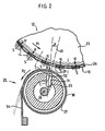
- FIG. 2 there is shown schematically a portion of the magnetic drum 10 seen in section, on a large scale, so that the magnetized areas 14 formed on the surface 13 of this drum have, in this figure, a relatively large size.
- each of these magnetized zones has, in reality, a size of the order of 100 to 200 ⁇ m, that is to say has, for example, a square section of the order of 100 to 200 ⁇ ms aside.
- the magnetized zones which have been shown in FIG. 2 have not been drawn to the scale of the drawing.
- the magnetic drum 10 consists, in a manner known in the prior art, of a cylindrical support 25 formed of a magnetically soft material with high magnetic permeability (such as iron or iron alloy -silicon), this support being coated with a layer 26 of magnetic material with high coercivity such as, for example, the nickel-cobalt magnetic alloy.
- This layer 26 is intended to be magnetized transversely, the support 25 then serving as a magnetic shunt.
- the magnetized zones 14 which are formed on the magnetic drum 10 by the recording member 12 all have magnetization axes NS oriented perpendicular to the surface 13 of the drum.
- the recording member 12 is produced in a known manner, so that these magnetization axes are all oriented in the same direction.
- the magnetized zones 14 all have, on their external face, a south magnetic polarity (S).
- these magnetized zones all have the same magnetization intensity, each of these magnetizations being represented, in FIG. 2, by an arrow whose length is proportional to the value of this magnetization.
- these magnetized zones 14 are shown as they appear after they have passed in front of the application device 15, that is to say after they have been coated with a layer of developer.
- the thickness of this layer is relatively large, that is to say generally greater than a hundred microns, whereas, on the magnetized zones 14 which have passed in front of the retouching device, the thickness of this layer is reduced to a value which, under conditions which will be explained below, can reach around thirty microns.
- the retouching device 20 which equips the printing machine which has just been described comprises an endless transport element 27 which, in the embodiment illustrated in FIG. 2, is in the form of a hollow cylinder, the axis of rotation 28 is parallel to the axis 11 of the drum 10.
- This cylinder which is made of a non-magnetic material such as, for example, aluminum, is disposed along a part 29 of the circular path that follows the surface 13 of the drum during the rotation of this drum, this part 29 situated downstream from the point where the developer particles coming from the reservoir 16 are applied to this surface 13 extending over a length of the order of one at two centimeters.
- the cylinder 27, which is continuously rotated about its axis 28, is placed very close to the surface 13 of the drum 10.
- this cylinder 27 is spaced from the surface 13 by a distance which, practically does not exceed three millimeters. Thus, in the example described, this distance is equal to 1.5 millimeters. It should also be noted that, as can be seen in FIG. 2, the drum 10 and the cylinder 27 both rotate in the same direction, this direction being, in the example described, opposite to that of the needles of a watch. Under these conditions, the external surface 30 of the cylinder 27 passes in front of the path part 29 in a direction opposite to that of the displacement of the surface 13 of the drum. It is useful to indicate here that, in the example described, this surface 13 moves at a linear speed equal to thirty centimeters per second, while the surface 30 of the cylinder 27 moves at a linear speed equal to 1.5 centimeters per second.
- the retouching device which is shown in FIG. 2 further comprises a magnetized element 31, in the form of a bar, which is housed inside the cylinder 27 and is placed near the path portion 29 which has been mentioned. upper.
- This permanent magnet 31 is oriented so that its magnetic pole which is closest to the path part 29 is that whose polarity is opposite to that presented by the magnetized zones 14 on their external face. In other words, the direction of magnetization of this magnet 31 is the same as that of the magnetized zones which pass past it.
- the magnetic pole of the magnet 31 which is closest to the part of the path 29 is that which has a north magnetic polarity (N ′), that is to say here the magnetic pole 32.
- N ′ north magnetic polarity
- the thickness of the cylinder 27 is always very small, this is that is to say generally between one millimeter and a few tenths of a millimeter, and that the end J of this nearest magnetic pole is spaced from the surface 13 of the drum by a distance D, the value of which will be determined a little further , but which, practically, is at most equal to five millimeters.
- the magnetic axis N'S 'of the magnet 31 is not oriented center C of the magnet 31, is normal to the part of the path 29, but is, on the contrary, inclined relative to this normal 40 in the opposite direction to that of the displacement of the surface 13 of the drum.
- This magnetic axis N'S 'then forms with this normal 40 an angle A whose value depends on the linear speed of movement of the surface 13, but does not however exceed 45 degrees.
- this angle A has a value practically equal to 35 degrees.
- this angle A has a value close to 25 degrees.
- the angle A has a value of about 15 degrees.
- Each of the developer particles which have been deposited on the same magnetized zone 14 is attracted to this zone with a force F M whose intensity depends not only on the value of the magnetization of this zone, but also on the distance h that separates this particle from this area.
- this magnetic force F M varies as a function of this distance h, according to a law of variation which is illustrated by the curve in solid lines 50 represented in the diagram of FIG. 3, the coordinates of the constituent points of this curve 50 being related to two axes of rectangular coordinates passing through the same origin 0, this origin 0 corresponding, on the surface 13, to the center of the magnetized zone.
- each magnetized zone 14 has a size close to 100 ⁇ m and where the permanent magnet 31 has a width practically equal to 6 millimeters, it has been found that, to reduce to about thirty of pm the thickness of the developer layer on each of the magnetized zones 14, this magnet 31 had to be spaced from the surface 31 of the drum by a distance D practically equal to 2.5 millimeters.
- the developer particles which remain on the surface 13 of the drum, outside of the magnetized zones 14, are also subjected to the attractive action exerted by the magnet 31 at the moment when they pass directly over this surface. magnet. Because the adhesion force which keeps these particles applied to this surface 13 is significantly less than that exerted by the magnet 31, these particles are detached from this surface and they then come to be applied to the external surface 30 of cylinder 27.
- the surface 30 of the cylinder 27 on which the particles which have been detached from the drum under the action of the magnet 31 are applied is not smooth, but on the contrary has a certain roughness, the gaps between the most highs and the lowest points of this surface 30 however remaining less than 300 microns. Thanks to this roughness, the developer particles which have applied to the surface 30 are entrained during the rotation of the cylinder 27. A squeegee 34, the end of which is pressed against the surface 30, then allows these particles to 'be removed from the cylinder 27 and fall back into the tank 16, as can be seen in Figure 1.
- the retouching device which has just been described applies not only to a printing machine, the recording medium of which is constituted by a magnetic drum, but also to a printing machine, of which the recording medium is constituted, as as shown in FIG. 3, by an endless magnetic strip 110 stretched on rollers 111, 112, 113, 114, this strip being held pressed against a magnetic shunt 115 made up of a bar of magnetically soft material with high magnetic permeability.
- the printing machine which is shown schematically in Figure 3 has the same components as those of the machine shown in Figure 1, such as, for example, the magnetic recording member 12, the application device 15, etc. ....
- the running of this strip 110, in the direction indicated by the arrow D1 is provided by an electric motor, not shown, which drives one of the rollers in rotation, the other rollers being free to rotate.
- the printing machine which is shown in FIG. 3 can, of course, be equipped with the same retouching device as that which has been illustrated in FIG. 2.
- this retouching device 20 comprises, as can be seen in FIG. 3, a transport element in the form of an endless belt 127 stretched over three rollers 128, 129, 130, this strip 127 consisting of a flexible non-magnetic material such as, for example, rubber.
- the rollers 129 and 130 are arranged so that the portion of the strip 127 which is between these two rollers is parallel to a part 29 of the path followed by the magnetic strip 110 between the rollers 111 and 114 and is located in the immediate vicinity of this part 29.
- the endless strip 127 is driven in one direction, indicated by the arrow D2 in FIG.
- the permanent magnet 31 which is placed inside the path followed by the strip 127 and near the part 29 is oriented, as can be seen in FIG. 3 , so that its magnetic pole which is closest to this part 29 is the one whose polarity is opposite to that presented by the magnetized zones opposite the strip 127. It is also seen in FIG. 3, that the axis magnetic of magnet 31 is inclined with respect to the straight line 40 which, passing through the center C of this magnet, is normal to the part 29, this inclination being carried out in the opposite direction to that of the displacement of the magnetic strip 110. This magnetic axis then forms with the straight 40 and an angle A whose value, defined above in the text, depends on the speed of movement of the magnetic strip 110, but does not exceed 45 degrees.
- the retouching device of the present invention it has been successful not only to remove the developer particles deposited outside the magnetized areas of the magnetic recording medium, but also to significantly reduce the thickness of the developer layer on each of these magnetized areas. This is how we were able, for example, on magnetized zones having a size of the order of 100 to 200 microns, reduce the thickness of the developer layer deposited on these areas from 100 to 30 microns.
- the retouching device of the invention allows the developer particles remaining on the magnetized areas to regroup towards the centers of these areas, which further improves the quality of the impression obtained during the transfer of these particles onto the paper.
Landscapes
- Physics & Mathematics (AREA)
- General Physics & Mathematics (AREA)
- Magnetic Brush Developing In Electrophotography (AREA)
- Printers Or Recording Devices Using Electromagnetic And Radiation Means (AREA)
- Silver Salt Photography Or Processing Solution Therefor (AREA)
Abstract
Description
La présente invention se rapporte à un appareil de développement d'images magnétiques latentes et, plus particulièrement à un dispositif de retouche qui, dans cet appareil, est destiné à éliminer les particules de révélateur en excès qui ont été déposées sur la surface d'enregistrement magnétique de cet appareil. Un dispositif de retouche de ce genre trouve notamment son application dans les machines imprimantes magnétiques.The present invention relates to an apparatus for developing latent magnetic images and, more particularly to a retouching device which, in this apparatus, is intended to remove the excess developer particles which have been deposited on the recording surface. magnetic of this device. A touch-up device of this kind finds its application in particular in magnetic printing machines.
Dans les équipements modernes utilisés pour le traitement de l'information, on emploie de plus en plus des imprimantes rapides dans lesquelles l'impression des caractères est réalisée sans pour cela faire appel à l'impact de types d'impression en relief sur une feuille de papier réceptrice. Ces machines imprimantes, dites non impact, comportent généralement un support d'enregistrement qui, constitué le plus souvent par un tambour rotatif ou une courroie sans fin, est pourvu d'une surface d'enregistrement sur laquelle on peut former, par voie électrostatique ou magnétique, des zones sensibilisées correspondant aux caractères à imprimer, ces zones étant capables d'attirer des particules solides d'un produit révélateur pulvérulent.In modern equipment used for information processing, more and more rapid printers are used in which the printing of the characters is carried out without for that calling upon the impact of types of relief printing on a sheet. of receiving paper. These so-called non-impact printing machines generally comprise a recording medium which, most often consisting of a rotary drum or an endless belt, is provided with a recording surface on which it is possible to form, electrostatically or magnetic, sensitized areas corresponding to the characters to be printed, these areas being capable of attracting solid particles of a powdery developer product.
Pour appliquer des particules solides de révélateur sur le support d'enregistrement d'une machine imprimante de ce type, on peut utiliser divers dispositifs d'application tels que, par exemple, celui qui a été accessoirement décrit et représenté dans le US-A-3.161.544. Cependant, malgré tout le soin apporté à la réalisation de ces dispositifs, il est difficile d'éviter que les particules de révélateur ne se déposent, non seulement en surabondance sur les zones sensiblisées du support d'enregistrement mais aussi, même en très faible quantité, en dehors de ces zones. On attribue ce phénomène au fait que les particules, lorsqu'elles se chargent d'humidité ou d'électricité statique, ou encore lorsqu'elles subissent un ramollissement qui, même faible, les rend plus ou moins collantes, adhèrent à la surface avec laquelle elles ont été mises en contact. Le dépôt excessif de particules de révélateur sur les zones sensibilisées du support d'enregistrement est indésirable parce que, lors du transfert de ce révélateur sur la feuille de papier réceptrice, le révélateur qui a été déposé suivant la configuration de l'image formée par ces zones sensibilisées risque de s'étaler et de brouiller l'image. D'autre part, le dépôt de particules de révélateur en dehors des zones sensibilisées du support d'enregistrement est, lui aussi, indésirable du fait que ces particules, lorsqu'elles sont transférées sur le papier, forment un fond qui réduit le contraste entre l'image transférée et le fond original du papier. Pour éliminer l'excès de révélateur sur la surface du support d'enregistrement, on a utilisé, dans l'art antérieur, divers dispositifs de retouche. C'est ainsi qu'on connaît un dispositif de ce genre qui a été notamment décrit dans le FR-A-2.185.825 et dans lequel une masse de particules de révélateur, placée en contact avec la surface du support d'enregistrement et en aval du dispositif d'application des particules, décharge les particules qui adhèrent à ce support en dehors des zones sensibilisées, si bien que ces particules déchargées se détachent du support d'enregistrement et viennent s'agglomérer à cette masse. Toutefois, un tel dispositif de retouche ne donne pas entière satisfaction à l'usage du fait qu'il n'assure pas toujours une déchargé électrique complète des particules et qu'il ne permet pas, par conséquent, d'éliminer, de façon sûre, les particules de révélateur qui subsistent sur le support d'enregistrement, en dehors des zones sensibilisées de celui-ci.To apply solid developer particles to the recording medium of a printing machine of this type, various application devices can be used such as, for example, that which has been incidentally described and represented in US-A- 3,161,544. However, despite all the care taken in making these devices, it is difficult to prevent the developer particles from settling, not only in abundance on the sensitive areas of the recording medium but also, even in very small quantities , outside of these areas. This phenomenon is attributed to the fact that the particles, when they become charged with moisture or static electricity, or even when they undergo a softening which, even weak, makes them more or less sticky, adhere to the surface with which they were put in contact. Excessive deposition of developer particles on the sensitized areas of the recording medium is undesirable because, during the transfer of this developer onto the receiving paper sheet, the developer which has been deposited according to the configuration of the image formed by these sensitized areas risk spreading out and blurring the image. On the other hand, the deposition of developer particles outside the sensitized areas of the recording medium is also undesirable because these particles, when transferred to the paper, form a background which reduces the contrast between the transferred image and the original background of the paper. To remove excess developer from the surface of the recording medium, various touch-up devices have been used in the prior art. This is how a device of this type is known which has been described in particular in FR-A-2,185,825 and in which a mass of developer particles, placed in contact with the surface of the recording medium and in downstream of the particle application device, discharges the particles which adhere to this support outside the sensitized zones, so that these discharged particles detach from the recording medium and come to agglomerate with this mass. However, such a retouching device does not give complete satisfaction to the use of the fact that it does not always ensure a complete electric discharge of the particles and that it does not therefore make it possible to safely eliminate , the developer particles which remain on the recording medium, outside of the sensitized zones of the latter.
On connaît également un dispositif de retouche qui a été décrit dans le brevet français FR-A-2.066.151 et qui comporte un ensemble magnétique tournant à l'intérieur d'un manchon cylindrique fixe, cet ensemble étant lui-même formé d'une pluralité d'éléments magnétiques, en forme de secteur, disposés côte-à-côte tout autour d'un arbre tournant, ces éléments étant magnétisés de manière à présenter à leur surface périphérique des zones aimantées périphériques dont la polarité magnétique reste constante suivant une direction parallèle à l'arbre, mais alterne lorsqu'on passe d'une zone périphérique à la zone périphérique suivante. Toutefois, avec ce dispositif de retouche dans lequel les éléments magnétiques qui sont logés à l'intérieur du manchon fixe défilent devant le support d'enregistrement dans le sens inverse à celui du déplacement de ce support, on n'obtient pas une élimination régulière des particules en excès, du fait que, sur certaines portions de ce support, cette élimination est trop prononcée, alors que, sur d'autres portions, elle est insuffisante.There is also known a touch-up device which has been described in French patent FR-A-2,066,151 and which comprises a magnetic assembly rotating inside a fixed cylindrical sleeve, this assembly itself being formed by a plurality of sector-shaped magnetic elements arranged side by side around a rotating shaft, these elements being magnetized so as to present at their peripheral surface peripheral magnetic zones whose magnetic polarity remains constant in a direction parallel to the tree, but alternates when moving from a peripheral zone to the next peripheral zone. However, with this retouching device in which the magnetic elements which are housed inside the fixed sleeve pass in front of the recording medium in the opposite direction to that of the movement of this medium, we do not obtain a regular elimination of the particles in excess, because, on certain portions of this support, this elimination is too pronounced, while, on other portions, it is insufficient.
On peut supprimer cet inconvénient, en utilisant le dispositif de retouche qui a été décrit dans le FR-A-2.322. 393 et qui permet d'éliminer les particules de révélateur en excès qui se trouvent sur une bande magnétique sans fin sur laquelle une image latente magnétique a été formée. Ce dispositif de retouche comprend un rouleau de guidage de rayon R, sur laquelle passe la bande magnétique sans fin. Lorsque cette bande est entraînée à une vitesse constante V les particules de révélateur qui se trouvent sur cette bande sont soumises, lors de leur passage devant ce rouleau de guidage, à l'action d'une force centrifuge dont la valeur, sur chaque particule de masse M, est égale à MV2/R. Dans ces conditions, on peut, en choisissant convenablement la vitesse d'entraînement de la bande et le rayon du rouleau de guidage, ajuster l'intensité de cette force centrifuge de façon telle que sa valeur soit supérieure à celle des forces qui retiennent les particules sur les zones de fond de la bande, tout en étant cependant insuffisante pour détacher la totalité des particules qui se trouvent sur les zones magnétisées de cette bande. Les particules de révélateur en excès qui ont été ainsi détachées de la bande sont alors éliminées au moyen d'un aspirateur disposé à proximité du rouleau de guidage. On a toutefois, observé que, pour retirer les particules de révélateur en excès sur cette bande magnétique, il était nécessaire que l'accélération communiquée par cette force centrifuge soit au moins égale à 10g, g étant la valeur de l'accélération de la pesanteur. Il en résulte que, dans le cas où le rouleau de guidage utilisé dans ce dispositif de retouche a un diamètre de vingt millimètres, la bande magnétique sans fin doit être entraînée à une vitesse au moins égale à un mètre par seconde. Une vitesse de déplacement de cet ordre ne permet cependant pas d'utiliser ce dispositif de retouche dans les machines imprimantes magnétiques actuelles dans lesquelles la vitesse d'entraînement du support d'enregistrement ne dépasse pratiquement pas 30 cm/s. Afin que ce dispositif de retouche puisse être appliqué à une telle machine imprimante, on devrait en effet réduire le diamètre du rouleau de guidage, mais cette solution conduirait à choisir un rouleau de guidage dont le diamètre ne devrait pas dépasser deux millimètres. Un rouleau de guidage de cette taille serait alors nécessairement fragile et son emploi, dans une machine imprimante magnétique, n'offrirait pas toute la sécurité désirable.This drawback can be eliminated by using the retouching device which has been described in FR-A-2.322. 393 and which makes it possible to remove the excess developer particles which are on an endless magnetic strip on which a latent magnetic image has been formed. This retouching device comprises a guide roller with radius R, over which the endless magnetic strip passes. When this strip is driven at a constant speed V, the developer particles which are on this strip are subjected, during their passage in front of this guide roller, to the action of a centrifugal force whose value, on each particle of mass M, is equal to MV 2 / R. Under these conditions, it is possible, by suitably choosing the drive speed of the strip and the radius of the guide roller, to adjust the intensity of this centrifugal force so that its value is greater than that of the forces which retain the particles. on the bottom areas of the strip, while however being insufficient to detach all of the particles which are on the magnetized areas of this strip. The excess developer particles which have thus been detached from the strip are then eliminated by means of a vacuum cleaner located near the guide roller. However, it has been observed that, in order to remove the excess developer particles on this magnetic strip, it was necessary for the acceleration communicated by this centrifugal force to be at least equal to 10 g, g being the value of the acceleration of gravity . It follows that, in the case where the guide roller used in this retouching device has a diameter of twenty millimeters, the endless magnetic strip must be driven at a speed at least equal to one meter per second. However, a speed of movement of this order does not allow this retouching device to be used in current magnetic printing machines in which the drive speed of the recording medium does not practically exceed 30 cm / s. So that this retouching device can be applied to such a printing machine, the diameter of the guide roller should indeed be reduced, but this solution would lead to choosing a guide roller whose diameter should not exceed two millimeters. A guide roller of this size would then necessarily be fragile and its use, in a magnetic printing machine, would not offer all the desired security.
La présente invention remédie aux inconvénients de la technique antérieure et propose un appareil de développement d'images magnétiques latentes qui comporte un dispositif de retouche capable d'éliminer, de façon sûre et homogène, les particules de révélateur en excès se trouvant sur le support d'enregistrement de cet appareil, et cela même lorsque ce support d'enregistrement est entraîné à une vitesse de l'ordre de quelques dizaines de centimètres par seconde.The present invention overcomes the drawbacks of the prior art and proposes an apparatus for developing latent magnetic images which comprises a retouching device capable of safely and homogeneously removing the excess developer particles on the support of recording of this device, even when this recording medium is driven at a speed of the order of a few tens of centimeters per second.
Plus précisément, la présente invention concerne un appareil de développement d'images magnétiques latentes, comprenant un support entraîné dans un sens prédéterminé et pourvu d'une surface d'enregistrement magnétique sur laquelle des zones magnétisées présentant la même polarité magnétique ont été formées, un dispositif applicateur pour appliquer sur ces zones magnétisées des particules d'un révélateur magnétique pulvérulent, et un dispositif de retouche pour éliminer les particules de révélateur en excès qui ont été déposées sur cette surface, ce dispositif de retouche étant constitué:
- - d'un élément de transport sans fin entraîné de façon continue et disposée le long d'une partie du trajet suivi par ladite surface d'enregistrement, de manière que sa surface externe défile devant cette partie, à proximité immédiate de celle-ci,
- - et d'un élément magnétisé en permanence, en forme de barreau, placé à l'intérieur du chemin suivi par cet élément de transport sans fin, à proximité de ladite partie de trajet, cet appareil étant caractérisé en ce que cet élément magnétisé est orienté de telle manière que son pôle magnétique le plus proche de cette partie est celui dont la polarité est opposée à celle desdites zones magnétisées, et que son axe magnétique est incliné, par rapport à la droite qui passe par le centre de cet élément magnétisé et qui est normale à cette partie, dans le sens inverse à celui du déplacement de la surface d'enregistrement, l'angle formé par cet axe magnétique avec cette droite étant d'autant plus grand que la vitesse de déplacement de cette surface d'enregistrement magnétique est plus élevée, mais ne dépasse pas 45 degrés. L'invention sera mieux comprise et d'autres buts et avantages de celle-ci apparaîtront mieux dans la description suivante, donné à titre d'exemple non limitatif, et en se référant aux dessins annexés sur lesquels:
- - la figure 1, représente une vue schématique partielle d'une machine imprimante magnétique munie d'un dispositif de retouche établi selon l'invention,
- - la figure 2, est une vue agrandie, en coupe, montrant les éléments constitutifs du dispositif de retouche qui équipe la machine représentée sur la figure 1,
- - la figure 3, représente une vue schématique partielle d'un autre mode de réalisation d'une machine imprimante magnétique à laquelle s'applique le dispositif de retouche de l'invention, et
- - la figure 4, est un diagramme illustrant la façon dont varient les forces d'attraction magnétiques exercées sur les particules de révélateur déposées sur le support d'enregistrement de la machine imprimante représentée sur la figure 1.
- - an endless transport element driven continuously and arranged along part of the path followed by said recording surface, so that its external surface passes in front of this part, in the immediate vicinity thereof,
- - And a permanently magnetized element, in the form of a bar, placed inside the path followed by this endless transport element, near said part of the path, this device being characterized in that this magnetized element is oriented in such a way that its magnetic pole closest to this part is that whose polarity is opposite to that of said magnetized zones, and that its magnetic axis is inclined, relative to the straight line which passes through the center of this magnetized element and which is normal to this part, in the opposite direction to that of the displacement of the recording surface, the angle formed by this magnetic axis with this straight line being all the greater as the speed of displacement of this recording surface magnetic is higher, but does not exceed 45 degrees. The invention will be better understood and other objects and advantages thereof will appear better in the following description, given by way of nonlimiting example, and with reference to the appended drawings in which:
- FIG. 1 represents a partial schematic view of a magnetic printing machine provided with a retouching device established according to the invention,
- FIG. 2 is an enlarged view, in section, showing the constituent elements of the retouching device which equips the machine shown in FIG. 1,
- FIG. 3 represents a partial schematic view of another embodiment of a magnetic printing machine to which the retouching device of the invention applies, and
- FIG. 4 is a diagram illustrating how the magnetic attraction forces exerted on the developer particles deposited on the recording medium of the printing machine shown in FIG. 1 vary.
La machine imprimante qui a été représentée schématiquement sur la figure 1, comprend un support d'enregistrement magnétique constitué, dans l'exemple considéré, par un tambour magnétique 10 monté sur un axe horizontal 11. Ce tambour est entraîné en rotation, dans le sens de la flèche R1, par un moteur électrique (non représenté). L'enregistrement des informations sur ce tambour 10 est réalisé par un organe d'enregistrement magnétique 12 disposé à proximité de la surface externe 13 de ce tambour. Dans l'exemple considéré, cet organe 12 est formé d'un ensemble comprenant plusieurs têtes d'enregistrement magnétique qui, disposées les unes à côté des autres, sont alignées parallèlement à l'axe de rotation 11 du tambour. Chacune de ces têtes engendre, lorsqu'elle est excitée à différentes reprises par un courant électrique, un champ magnétique variable qui a pour effet de créer des domaines ou zones magnétisées 14 sur la surface 13 du tambour qui défile devant ces têtes. Les instants d'excitation de ces têtes sont déterminés de manière connue, de façon à obtenir sur cette surface 13 des ensembles de zones magnétisées, ensembles appelés encore images magnétiques latentes dont la forme correspond à celle des caractères à imprimer. Les zones magnétisées 14 du tambour 10 passent ensuite devant un dispositif d'application 15 qui est disposé au-dessous du tambour 10 et qui permet d'appliquer sur la surface 13 de ce tambour des particules d'un révélateur pulvérulent contenu dans un réservoir 16. Dans l'exemple de réalisation illustré par la figure 1, ce dispositif d'application 15 comprend, de façon connue dans l'état de la technique, d'une part un cylindre magnétique rotatif 17 qui prélève des particules de révélateur se trouvant dans le réservoir 16 pour les amener au voisinage de la surface du tambour 10, d'autre part un déflecteur fixe 18 qui est interposé entre le cylindre magnétique 17 et le tambour 10 pour recueillir les particules transportées par ce cylindre 17 et les appliquer sur la surface de ce tambour.The printing machine which has been shown diagrammatically in FIG. 1 comprises a magnetic recording medium constituted, in the example considered, by a
Les particules de révélateur qui sont ainsi appliquées sur le tambour 10 n'adhèrent, en principe, que sur les zones magnétisées de celui-ci, de sorte que ces zones, après être passées devant le dispositif d'application 15, apparaissent revêtues d'une couche de révélateur, formant ainsi des dépôts 19 de particules sur la surface 13 du tambour. Ces dépôts 19 passent alors devant un dispositif de retouche 20 qui sera décrit plus loin et qui a pour rôle d'éliminer les particules de révélateur qui ont adhéré ailleurs que sur les zones magnétisées 14, ainsi que les particules qui se trouvent en surnombre sur ces zones. Après quoi, les particules de révélateur qui subsistent sur le tambour 10 sont transférées, en quasi totalité, sur une feuille de papier 21 qui est appliquée sur le tambour 10 au moyen d'un rouleau de pression 22. Les particules résiduelles de révélateur qui, lorsque ce transfert est réalisé, se trouvent encore sur le tambour 10 sont alors enlevées au moyen d'un dispositif de nettoyage 23. Les zones magnétisées qui ont défilé devant le dispositif de nettoyage 23 passent ensuite devant un dispositif d'effacement 24, ce qui permet aux portions du tambour 10, qui ont été ainsi démagnétisées, de pouvoir être à nouveau magnétisées lorsqu'elles se représentent devant l'organe d'enregistrement 12.The developer particles which are thus applied to the
Le révélateur pulvérulent qui est contenu dans le réservoir 16 de la machine imprimante que l'on vient de décrire est constitué de particules magnétiques enduites d'une résine qui, par chauffage, est capable de fondre et de se fixer sur la feuille de papier 21 sur laquelle elle a été déposée. Cette fusion est normalement provoquée par un dispositif de chauffage que traverse la feuille de papier 21 après être passée sur le rouleau de pression 22. Toutefois, ce dispositif de chauffage, qui est de type connu, n'a pas été représenté sur la figure 1 pour la raison qu'il ne fait pas partie de l'invention.The powder developer which is contained in the
Sur la figure 2, on a représenté schématiquement une partie du tambour magnétique 10 vu en coupe, à grande échelle, de façon que les zones magnétisées 14 formées sur la surface 13 de ce tambour aient, sur cette figure, une taille relativement importante. Il faut cependant noter que chacune de ces zones magnétisées a, en réalité, une taille de l'ordre de 100 à 200 pm, c'est-à-dire présente, par exemple, une section carrée de l'ordre de 100 à 200 µms de côté. Par ailleurs, pour des raisons évidentes de clarté des dessins, les zones magnétisées qui ont été représentées sur la figure 2 n'ont pas été tracées à l'échelle du dessin. Il faut signaler encore que le tambour magnétique 10 est constitué, de façon connue dans l'état de la technique, d'un support cylindrique 25 formé d'un matériau magnétiquement doux à haute perméabilité magnétique (tel que le fer ou l'alliage fer-silicium), ce support étant revêtu d'une couche 26 de matériau magnétique à haute coercivité tel que, par exemple, l'alliage magnétique nickel-cobalt. Cette couche 26 est prévue pour être magnétisée transversalement, le support 25 servant alors de shunt maqnétique. Dans ces conditions, les zones magnétisées 14 qui sont formées sur le tambour magnétique 10 par l'organe d'enregistrement 12 présentent toutes des axes d'aimantation NS orientés perpendiculairement à la surface 13 du tambour. L'organe d'enregistrement 12 est réalisé de manière connue, de façon que ces axes d'aimantation soient tous orientés dans le même sens. C'est ainsi que, dans l'exemple de réalisation qui est représenté sur la figure 2, les zones magnétisées 14 présentent toutes, sur leur face externe, une polarité magnétique sud (S). En outre, ces zones magnétisées présentent toutes la même intensité d'aimantation, chacune de ces aimantations étant représentée, sur la figure 2, par une flèche dont la longueur est proportionnelle à la valeur de cette aimantation. Sur la figure 2, ces zones magnétisées 14 sont montrées telles qu'elles apparaissent après leur passage devant le dispositif d'application 15, c'est-à-dire après qu'elles aient été revêtues d'une couche de révélateur. Il y a lieu de signaler ici que, sur les zones magnétisées 14 qui ne sont pas encore passées devant le dispositif de retouche 20, l'épaisseur de cette couche est relativement importante, c'est-à-dire généralement supérieure à une centaine de microns, alors que, sur les zones magnétisées 14 qui sont passées devant le dispositif de retouche, l'épaisseur de cette couche est réduite à une valeur qui, dans des conditions qui seront exposées plus loin, peut atteindre une trentaine de microns.In Figure 2, there is shown schematically a portion of the
Le dispositif de retouche 20 qui équipe la machine imprimante que l'on vient de décrire comprend un élément de transport sans fin 27 qui, dans l'exemple de réalisation illustré par la figure 2, se présente sous la forme d'un cylindre creux dont l'axe de rotation 28 est parallèle à l'axe 11 du tambour 10. Ce cylindre, qui est réalisé en un matériau amagnétique tel que, par exemple, l'aluminium, est disposé le long d'une partie 29 du trajet circulaire que suit la surface 13 du tambour au cours de la rotation de ce tambour, cette partie 29 située en aval du point où les particules de révélateur provenant du réservoir 16 sont appliquées sur cette surface 13 s'étendant sur une longueur de l'ordre de un à deux centimètres. Le cylindre 27, qui est entraîné en rotation, de façon continue, autour de son axe 28, est placé très près de la surface 13 du tambour 10. Plus précisément, ce cylindre 27 est écarté de la surface 13 d'une distance qui, pratiquement, n'excède pas trois millimètres. C'est ainsi que, dans l'exemple décrit, cette distance est égale à 1,5 millimètre. Il faut signaler, par ailleurs, que, comme on peut le voir sur la figure 2, le tambour 10 et le cylindre 27 tournent tous les deux dans le même sens, ce sens étant, dans l'exemple décrit, inverse de celui des aiguilles d'une montre. Dans ces conditions, la surface externe 30 du cylindre 27 défile devant la partie de trajet 29 dans un sens inverse à celui du déplacement de la surface 13 du tambour. Il est utile d'indiquer ici que, dans l'exemple décrit, cette surface 13 se déplace à une vitesse linéaire égale à trente centimètres par seconde, tandis que la surface 30 du cylindre 27 se déplace à une vitesse linéaire égale à 1,5 centimètres par seconde.The
Le dispositif de retouche qui est représenté sur la figure 2 comprend en outre, un élément magnétisé 31, en forme de barreau, qui est logé à l'intérieur du cylindre 27 et est placé à proximité de la partie de trajet 29 dont on a parlé plus haut. Cet élément magnétisé 31, constitué dans l'exemple décrit par un aimant permanent, possède deux pôles opposés 32 et 33 dont l'un, 32, présente une polarité magnétique nord (N') et dont l'autre 33, présente une polarité magnétique sud (S'). Cet aimant permanent 31 est orienté de telle sorte que son pôle magnétique qui est le plus proche de la partie de trajet 29 est celui dont la polarité est opposée à celle présentée par les zones magnétisées 14 sur leur face externe. En d'autres termes, le sens d'aimantation de cet aimant 31 est le même que celui des zones magnétisées qui défilent devant lui. C'est ainsi que, l'exemple illustré par la figure 2 dans lequel les zones magnétisées 14 présentent, sur leur face externe, une polarité magnétique sud (S), le pote magnétique de l'aimant 31 qui est le plus proche de la partie de trajet 29 est celui qui présente une polarité magnétique nord (N'), c'est-à-dire ici le pôle magnétique 32. Il faut signaler par ailleurs que l'épaisseur du cylindre 27 est toujours très faible, c'est-à-dire généralement comprise entre un millimètre et quelques dizièmes de millimètres, et que l'extrémité J de ce pôle magnétique le plus proche est écarté de la surface 13 du tambour d'une distance D dont la valeur sera déterminée un peu plus loin, mais qui, pratiquement, est au plus égale à cinq millimètres. C'est ainsi que, dans l'exemple décrit, 32 est écartée de cette surface 13 est égale à 2,5 millimètres. De plus, comme on peut le voir sur la figure 2, l'axe , magnétique N'S' de l'aimant 31 n'est pas orienté centre C de l'aimant 31, est normale à la partie du trajet 29, mais est, au contraire, incliné par rapport à cette normale 40 dans le sens inverse à celui du déplacement de la surface 13 du tambour. Cet axe magnétique N'S' forme alors avec cette normale 40 un angle A dont la valeur dépend de la vitesse linéaire de déplacement de la surface 13, mais ne dépasse cependant pas 45 degrés. C'est ainsi que, dans l'exemple décrit où la surface 13 se déplace à une vitesse linéaire égale à trente centimètres par seconde, cet angle A a une valeur pratiquement égale à 35 degrés. Dans le cas où la vitesse de déplacement de la surface 13 est de l'ordre de dix centimètres à la seconde, cet angle A a une valeur voisine de 25 degrés. De même, pour une vitesse linéaire de déplacement de la surface 13 égale à cinq centimètres par seconde, l'angle A a une valeur d'environ 15 degrés.The retouching device which is shown in FIG. 2 further comprises a
Chacune des particules de révélateur qui ont éte déposées sur une même zone magnétisée 14 est attirée par cette zone avec une force FM dont l'intensité dépend, non seulement de la valeur de l'aimantation de cette zone, mais également de la distance h qui sépare cette particule de cette zone. On considèrera, dans l'exemple décrit, que cette force magnétique FM varie en fonction de cette distance h, suivant une loi de variation qui est illustrée par la courbe en traits pleins 50 représentée sur le diagramme de la figure 3, les coordonnées des points constitutifs de cette courbe 50 étant rapportées à deux axes de coordonnées rectangulaires passant par une même origine 0, cette origine 0 correspondant, sur la surface 13, au centre de la zone magnétisée. De même, lorsque cette zone magnétisée arrive à l'aplomb de l'aimant 31 du dispositif de retouche 20, chacune des particules de révélateur qui ont été déposées sur cette zone est soumise, de la part de cet aimant permanent 31, à une force magnétique attractive FR dont l'intensité dépend, non seulement de la valeur de l'induction magnétique de cet aimant, mais également de la distance d qui sépare cette particule de l'extrémité J du pôle magnétique 32 de cet aimant. Sur le diagramme de la figure 4, la loi de variation de cette force magnétique FR en fonction de cette distance d, a été illustrée par la courbe en traits mixtes 51, les coordonnées des points constitutifs de cette courbe 51 étant rapportées à deux axes de coordonnées rectangulaires passant par le point J. Lorsque la zone magnétisée 14 se trouve à l'aplomb de l'aimant 31, c'est-à-dire à la distance OJ = D de l'extrémité J de cet aimant, les courbes 50 et 51 précitées se coupent alors en un point I dont l'abscisse, considérée par rapport à l'origine 0, est désignée par e1 sur le diagramme de la figure 4. On comprend, dans ces conditions, que, pour les particules qui, sur cette zone 14, se trouvent à une distance e2 de la surface 13 supérieure à el, la force magnétique F2 exercée par l'aimant 31 sur ces particules est supérieure à la force K2 exercée par cette zone sur ces mêmes particules. En conséquence, ces particules viennent s'appliquer sur la surface externe 30 du cylindre 27 . Au contraire, pour les particules qui, sur cette zone 14, se trouvent à une distance e3 de la surface 13 inférieure à e" la force magnétique F3 exercée par l'aimant 31 est inférieure à la force K3 exercée par cette zone. En conséquence, ces particules restent appliquées sur la zone magnétisée 14. Etant donné que l'allure des courbes 50 et 51 est conditionnée par les dimensions et les valeurs des aimantations des zones magnétisées 14 et de l'aimant permanent 31, on voit alors que, après avoir mesuré expérimentalement les forces exercées en différents points par cet aimant et chacune de ces zones et avoir tracé en conséquence les courbes correspondantes 50 et 51, on peut déterminer la valeur de la distance D dont cet aimant 31 doit être écarté dela surface 13 pour que l'abscisse e1 du point d'intersection I de ces deux courbes soit égale à la valeur de l'épaisseur de la couche de révélateur que l'on désire maintenir sur chacune de ces zones magnétisées. C'est ainsi que, dans l'exemple décrit, où chaque zone magnétisée 14 a une taille voisine de 100 µm et où l'aimant permanent 31 a une largeur pratiquement égale à 6 millimètres, on a trouvé que, pour réduire a une trentaine de pm l'épaisseur de la couche de révélateur sur chacune des zones magnétisées 14, cet aimant 31 devait être écarté de la surface 31 du tambour d'une distance D pratiquement égale à 2,5 millimètres.Each of the developer particles which have been deposited on the same magnetized
Il faut signaler encore que les particules de révélateur qui subsistent sur la surface 13 du tambour, en dehors des zones magnétisées 14, sont également soumises à l'action attractive exercée par l'aimant 31 au moment où elles passent à l'aplomb de cet aimant. Du fait que la force d'adhérence qui maintient ces particules appliquées sur cette surface 13 est notablement moins grande que celle exercée par l'aimant 31, ces particules se trouvent détachées de cette surface et elles viennent alors s'appliquer sur la surface externe 30 du cylindre 27.It should also be noted that the developer particles which remain on the
La surface 30 du cylindre 27 sur laquelle viennent s'appliquer les particules qui ont été détachées du tambour sous l'action de l'aimant 31 n'est pas lisse, mais présente au contraire une certaine rugosité, les écarts entre les points les plus hauts et les points les plus bas de cette surface 30 restant cependant inférieurs à 300 microns. Grâce à cette rugosité, les particules de révélateur qui sont venues s'appliquer sur la surface 30 sont entraînées au cours de la rotation du cylindre 27. Une raclette 34 dont l'extrémité est appuyée contre la surface 30, permet ensuite à ces particules d'être retirées du cylindre 27 et de retomber dans le réservoir 16, comme on peut le voir à la figure 1.The
Le dispositif de retouche qui vient d'être décrit s'applique, non seulement, à une machine imprimante dont le support d'enregistrement est constitué par un tambour magnétique, mais également à une machine imprimante dont le support d'enregistrement est constitué, comme le montre la figure 3, par une bande magnétique sans fin 110, tendue sur des rouleaux 111,112, 113,114, cette bande étant maintenue plaquée contre un shunt magnétique 115 constitué d'une barre de matériau magnétiquement doux à haute perméabilité magnétique. La machine imprimante qui est représentée schématiquement sur la figure 3 comporte les mêmes éléments constitutifs que ceux de la machine représentée sur la figure 1, tels que, par exemple, l'organe d'enregistrement magnétique 12, le dispositif d'application 15, etc .... Le défilement de cette bande 110, dans le sens indiqué par la flèche D1, est assuré par un moteur électrique, non représenté, qui entraîne en rotation l'un des rouleaux, les autres rouleaux étant libres en rotation.The retouching device which has just been described applies not only to a printing machine, the recording medium of which is constituted by a magnetic drum, but also to a printing machine, of which the recording medium is constituted, as as shown in FIG. 3, by an endless
La machine imprimante qui est représentée sur la figure 3 peut, bien entendu, être équipée du même dispositif de retouche que celui qui a été illustré sur la figure 2.The printing machine which is shown in FIG. 3 can, of course, be equipped with the same retouching device as that which has been illustrated in FIG. 2.
Toutefois, dans un autre mode de réalisation, ce dispositif de retouche 20 comprend, ainsi qu'on peut le voir sur la figure 3, un élément de transport se présentant sous la forme d'une bande sans fin 127 tendue sur trois rouleaux 128, 129, 130, cette bande 127 étant constituée d'une matière souple amagnétique telle que, par exemple, le caoutchouc. Les rouleaux 129 et 130 sont disposés de manière que la portion de la bande 127 qui est comprise entre ces deux rouleaux soit parallèle à une partie 29 du trajet suivi par la bande magnétique 110 entre les rouleaux 111 et 114 et soit située à proximité immédiate de cette partie 29. La bande sans fin 127 est entraînée dans un sens, indiqué par la flèche D2 sur la figure 3, tel que la portion de la bande 127 qui est comprise entre les rouleaux 129 et 130 défile en sens inverse du sens suivant laquelle se déplace la bande magnétique 110 entre les rouleaux 114 et 111. L'aimant permanent 31 qui est placé à l'intérieur du trajet suivi par la bande 127 et à proximité de la partie 29 est orienté, comme on le voit sur la figure 3, de telle manière que son pôle magnétique qui est le plus proche de cette partie 29 est celui dont la polarité est opposée à celle présentée par les zones magnétisées en regard de la bande 127. On voit également sur la figure 3, que l'axe magnétique de l'aimant 31 est incliné par rapport à la droite 40 qui, passant par le centre C de cet aimant, est normale à la partie 29, cette inclinaison étant réalisée dans le sens inverse à celui du déplacement de la bande magnétique 110. Cet axe magnétique forme alors avec la droite 40 et un angle A dont la valeur, définie plus haut dans le texte, dépend de la vitesse de déplacement de la bande magnétique 110, mais n'excède pas 45 degrés.However, in another embodiment, this
En utilisant, dans les conditions qui ont été exposées en détail ci-dessus, le dispositif de retouche de la présente invention, on a réussi, non seulement à éliminer lés particules de révélateur déposées en dehors des zones magnétisées du support d'enregistrement magnétique, mais également à réduire notablement l'épaisseur de la couche de révélateur sur chacune de ces zones magnétisées. C'est ainsi que l'on a pu, par exemple, sur des zones magnétisées ayant une taille de l'ordre de 100 à 200 microns, réduire de 100 à 30 microns l'épaisseur de la couche de révélateur déposée sur ces zones. En outre, le dispositif de retouche de l'invention permet aux particules de révélateur subsistant sur les zones magnétisées de se regrouper vers les centres de ces zones, ce qui améliore encore la qualité de l'impression obtenue lors du transfert de ces particules sur le papier.By using, under the conditions which have been explained in detail above, the retouching device of the present invention, it has been successful not only to remove the developer particles deposited outside the magnetized areas of the magnetic recording medium, but also to significantly reduce the thickness of the developer layer on each of these magnetized areas. This is how we were able, for example, on magnetized zones having a size of the order of 100 to 200 microns, reduce the thickness of the developer layer deposited on these areas from 100 to 30 microns. In addition, the retouching device of the invention allows the developer particles remaining on the magnetized areas to regroup towards the centers of these areas, which further improves the quality of the impression obtained during the transfer of these particles onto the paper.
Claims (8)
Priority Applications (1)
| Application Number | Priority Date | Filing Date | Title |
|---|---|---|---|
| AT84402286T ATE31982T1 (en) | 1983-11-17 | 1984-11-13 | DEVELOPMENT DEVICE OF LATENT MAGNETIC IMAGE. |
Applications Claiming Priority (2)
| Application Number | Priority Date | Filing Date | Title |
|---|---|---|---|
| FR8318282A FR2555329B1 (en) | 1983-11-17 | 1983-11-17 | APPARATUS FOR DEVELOPING LATENT MAGNETIC IMAGES |
| FR8318282 | 1983-11-17 |
Publications (2)
| Publication Number | Publication Date |
|---|---|
| EP0142446A1 EP0142446A1 (en) | 1985-05-22 |
| EP0142446B1 true EP0142446B1 (en) | 1988-01-13 |
Family
ID=9294219
Family Applications (1)
| Application Number | Title | Priority Date | Filing Date |
|---|---|---|---|
| EP84402286A Expired EP0142446B1 (en) | 1983-11-17 | 1984-11-13 | Development apparatus for latent magnetic images |
Country Status (6)
| Country | Link |
|---|---|
| US (1) | US4610527A (en) |
| EP (1) | EP0142446B1 (en) |
| AT (1) | ATE31982T1 (en) |
| DE (1) | DE3468755D1 (en) |
| ES (1) | ES537747A0 (en) |
| FR (1) | FR2555329B1 (en) |
Families Citing this family (4)
| Publication number | Priority date | Publication date | Assignee | Title |
|---|---|---|---|---|
| FR2625574B1 (en) * | 1987-12-30 | 1990-09-14 | Bull Sa | DEVICE FOR ELIMINATING POLLUTION DUE TO ELECTRIC CHARGES ACQUIRED BY A PRINTING MEDIUM IN A MAGNETOGRAPHIC PRINTING MACHINE |
| FR2629606B1 (en) * | 1988-03-30 | 1990-11-09 | Bull Sa | DEVICE FOR FORMING MAGNETIC LATENT IMAGES ON THE RECORDING ELEMENT OF A MAGNETOGRAPHIC PRINTER |
| EP0526137B1 (en) * | 1991-07-26 | 1997-04-02 | Matsushita Electric Industrial Co., Ltd. | Electrophotographic method and apparatus employed therefor |
| KR0159306B1 (en) * | 1993-01-13 | 1999-03-20 | 모리시타 요이찌 | Electrophotographic device |
Family Cites Families (6)
| Publication number | Priority date | Publication date | Assignee | Title |
|---|---|---|---|---|
| US3804511A (en) * | 1970-07-29 | 1974-04-16 | Pelorex Corp | Method and apparatus utilizing magnetic storage for transferring graphical information |
| US4108546A (en) * | 1976-11-01 | 1978-08-22 | Xerox Corporation | Cleaning apparatus and electrostatographic reproducing machine |
| US4314018A (en) * | 1977-04-19 | 1982-02-02 | Mita Industrial Company, Ltd. | Cleaning process for an electrostatic copying apparatus |
| US4127327A (en) * | 1977-06-20 | 1978-11-28 | Xerox Corporation | Apparatuses incorporating a composite support member |
| JPH0244304Y2 (en) * | 1980-08-30 | 1990-11-26 | ||
| DE3119029C2 (en) * | 1981-05-13 | 1983-02-10 | Siemens AG, 1000 Berlin und 8000 München | Device for developing charge images arranged on a charge image carrier with the aid of a developer mixture consisting of toner and carrier particles |
-
1983
- 1983-11-17 FR FR8318282A patent/FR2555329B1/en not_active Expired
-
1984
- 1984-10-19 US US06/662,909 patent/US4610527A/en not_active Expired - Lifetime
- 1984-11-13 DE DE8484402286T patent/DE3468755D1/en not_active Expired
- 1984-11-13 AT AT84402286T patent/ATE31982T1/en not_active IP Right Cessation
- 1984-11-13 EP EP84402286A patent/EP0142446B1/en not_active Expired
- 1984-11-16 ES ES537747A patent/ES537747A0/en active Granted
Also Published As
| Publication number | Publication date |
|---|---|
| ATE31982T1 (en) | 1988-01-15 |
| ES8600816A1 (en) | 1985-10-16 |
| DE3468755D1 (en) | 1988-02-18 |
| FR2555329B1 (en) | 1986-02-14 |
| US4610527A (en) | 1986-09-09 |
| ES537747A0 (en) | 1985-10-16 |
| EP0142446A1 (en) | 1985-05-22 |
| FR2555329A1 (en) | 1985-05-24 |
Similar Documents
| Publication | Publication Date | Title |
|---|---|---|
| CH639501A5 (en) | PROCESS FOR DEVELOPING LATENT ELECTROSTATIC IMAGES AND DEVICE FOR IMPLEMENTING SAME. | |
| FR2564609A1 (en) | DEVELOPMENT METHOD AND APPARATUS | |
| FR2594566A1 (en) | METHOD AND APPARATUS FOR DEVELOPING A LATENT ELECTROSTATIC IMAGE | |
| FR2597625A1 (en) | APPARATUS FOR DEVELOPING A LATENT ELECTROSTATIC IMAGE, ESPECIALLY IN ELECTROCOPY | |
| FR2477734A1 (en) | APPARATUS FOR DEVELOPING A LATENT ELECTROSTATIC IMAGE | |
| EP0142446B1 (en) | Development apparatus for latent magnetic images | |
| FR2482737A1 (en) | ELECTROSTATIC IMAGE SUPPORT SHEET, METHOD AND APPARATUS FOR MANUFACTURING SUCH SHEET, AND METHOD AND APPARATUS FOR FORMING IMAGES BY ELECTROPHOTOGRAPHY | |
| EP0086683B1 (en) | Device for the application of solid particles on the recording support of a printing machine | |
| EP0328428B1 (en) | Device for intermittently applying particles of a pulverulent toner to the recording medium of a magnetographic printer | |
| FR2503408A1 (en) | ||
| CH630185A5 (en) | INSTALLATION FOR THE ELECTROPHOTOGRAPHIC REPRODUCTION OF AN IMAGE AND METHOD FOR ITS ACTION. | |
| EP0315509B1 (en) | Method for fixing a toner powder put on a sheet, and device for fixing this toner according to this method | |
| EP0099763B1 (en) | Toner powder applicator on the imaging roller of a non-impact printer | |
| EP0291392B1 (en) | Pulverulent substance for the lubrification of the recording medium of a magnetic printer | |
| EP0082742B1 (en) | Method and device for magnetographic copying | |
| EP0082740B1 (en) | Method and device for magnetographic copying | |
| EP0082741B1 (en) | Method and device for magnetographic copying | |
| EP0082739B1 (en) | Method and device for magnetographic copying | |
| FR2637992A1 (en) | ELECTROSTATIC RECORDING HEAD, IMAGE RECORDING DEVICE AND DISPLAY DEVICE COMPRISING SUCH HEAD, DEVICE FOR SUPPLYING DEVELOPMENT AGENT USED IN SUCH HEAD, AND METHOD FOR MANUFACTURING THE SAME | |
| EP0172767B1 (en) | Method and machine for magnetographic copying | |
| FR2527798A1 (en) | DEVICE FOR TRANSFERRING A MAGNETIC INK | |
| FR2625574A1 (en) | Device for eliminating contamination due to electric charges acquired by a printing support in a magnetographic printing machine | |
| FR2522838A1 (en) | Line of force straightening device for magnetic printer - reveals latent magnetic images by particles on magnetic support | |
| CH622365A5 (en) | Method for reproducing an image on a transfer medium | |
| EP0193691A1 (en) | Non-impact printing machine |
Legal Events
| Date | Code | Title | Description |
|---|---|---|---|
| PUAI | Public reference made under article 153(3) epc to a published international application that has entered the european phase |
Free format text: ORIGINAL CODE: 0009012 |
|
| AK | Designated contracting states |
Designated state(s): AT BE CH DE GB IT LI NL SE |
|
| 17P | Request for examination filed |
Effective date: 19850419 |
|
| 17Q | First examination report despatched |
Effective date: 19860929 |
|
| RAP1 | Party data changed (applicant data changed or rights of an application transferred) |
Owner name: BULL S.A. |
|
| ITF | It: translation for a ep patent filed | ||
| GRAA | (expected) grant |
Free format text: ORIGINAL CODE: 0009210 |
|
| AK | Designated contracting states |
Kind code of ref document: B1 Designated state(s): AT BE CH DE GB IT LI NL SE |
|
| REF | Corresponds to: |
Ref document number: 31982 Country of ref document: AT Date of ref document: 19880115 Kind code of ref document: T |
|
| GBT | Gb: translation of ep patent filed (gb section 77(6)(a)/1977) | ||
| REF | Corresponds to: |
Ref document number: 3468755 Country of ref document: DE Date of ref document: 19880218 |
|
| PLBE | No opposition filed within time limit |
Free format text: ORIGINAL CODE: 0009261 |
|
| STAA | Information on the status of an ep patent application or granted ep patent |
Free format text: STATUS: NO OPPOSITION FILED WITHIN TIME LIMIT |
|
| 26N | No opposition filed | ||
| ITTA | It: last paid annual fee | ||
| EAL | Se: european patent in force in sweden |
Ref document number: 84402286.3 |
|
| PGFP | Annual fee paid to national office [announced via postgrant information from national office to epo] |
Ref country code: SE Payment date: 19981019 Year of fee payment: 15 |
|
| PGFP | Annual fee paid to national office [announced via postgrant information from national office to epo] |
Ref country code: AT Payment date: 19981030 Year of fee payment: 15 |
|
| PGFP | Annual fee paid to national office [announced via postgrant information from national office to epo] |
Ref country code: BE Payment date: 19981109 Year of fee payment: 15 |
|
| PGFP | Annual fee paid to national office [announced via postgrant information from national office to epo] |
Ref country code: CH Payment date: 19981110 Year of fee payment: 15 |
|
| PGFP | Annual fee paid to national office [announced via postgrant information from national office to epo] |
Ref country code: NL Payment date: 19981130 Year of fee payment: 15 |
|
| PG25 | Lapsed in a contracting state [announced via postgrant information from national office to epo] |
Ref country code: AT Free format text: LAPSE BECAUSE OF NON-PAYMENT OF DUE FEES Effective date: 19991113 |
|
| PG25 | Lapsed in a contracting state [announced via postgrant information from national office to epo] |
Ref country code: SE Free format text: LAPSE BECAUSE OF NON-PAYMENT OF DUE FEES Effective date: 19991114 |
|
| PG25 | Lapsed in a contracting state [announced via postgrant information from national office to epo] |
Ref country code: LI Free format text: LAPSE BECAUSE OF NON-PAYMENT OF DUE FEES Effective date: 19991130 Ref country code: CH Free format text: LAPSE BECAUSE OF NON-PAYMENT OF DUE FEES Effective date: 19991130 Ref country code: BE Free format text: LAPSE BECAUSE OF NON-PAYMENT OF DUE FEES Effective date: 19991130 |
|
| BERE | Be: lapsed |
Owner name: S.A. BULL Effective date: 19991130 |
|
| PG25 | Lapsed in a contracting state [announced via postgrant information from national office to epo] |
Ref country code: NL Free format text: LAPSE BECAUSE OF NON-PAYMENT OF DUE FEES Effective date: 20000601 |
|
| REG | Reference to a national code |
Ref country code: GB Ref legal event code: 732E |
|
| REG | Reference to a national code |
Ref country code: CH Ref legal event code: PL |
|
| EUG | Se: european patent has lapsed |
Ref document number: 84402286.3 |
|
| NLV4 | Nl: lapsed or anulled due to non-payment of the annual fee |
Effective date: 20000601 |
|
| PGFP | Annual fee paid to national office [announced via postgrant information from national office to epo] |
Ref country code: GB Payment date: 20001127 Year of fee payment: 17 |
|
| PGFP | Annual fee paid to national office [announced via postgrant information from national office to epo] |
Ref country code: DE Payment date: 20010126 Year of fee payment: 17 |
|
| PG25 | Lapsed in a contracting state [announced via postgrant information from national office to epo] |
Ref country code: GB Free format text: LAPSE BECAUSE OF NON-PAYMENT OF DUE FEES Effective date: 20011113 |
|
| REG | Reference to a national code |
Ref country code: GB Ref legal event code: IF02 |
|
| PG25 | Lapsed in a contracting state [announced via postgrant information from national office to epo] |
Ref country code: DE Free format text: LAPSE BECAUSE OF NON-PAYMENT OF DUE FEES Effective date: 20020702 |