EP0142288A2 - Battery plate containing filler with conductive coating - Google Patents
Battery plate containing filler with conductive coating Download PDFInfo
- Publication number
- EP0142288A2 EP0142288A2 EP84307156A EP84307156A EP0142288A2 EP 0142288 A2 EP0142288 A2 EP 0142288A2 EP 84307156 A EP84307156 A EP 84307156A EP 84307156 A EP84307156 A EP 84307156A EP 0142288 A2 EP0142288 A2 EP 0142288A2
- Authority
- EP
- European Patent Office
- Prior art keywords
- plate
- plate according
- sheet
- resin
- lead
- Prior art date
- Legal status (The legal status is an assumption and is not a legal conclusion. Google has not performed a legal analysis and makes no representation as to the accuracy of the status listed.)
- Granted
Links
Images
Classifications
-
- H—ELECTRICITY
- H01—ELECTRIC ELEMENTS
- H01M—PROCESSES OR MEANS, e.g. BATTERIES, FOR THE DIRECT CONVERSION OF CHEMICAL ENERGY INTO ELECTRICAL ENERGY
- H01M4/00—Electrodes
- H01M4/02—Electrodes composed of, or comprising, active material
- H01M4/64—Carriers or collectors
- H01M4/66—Selection of materials
- H01M4/68—Selection of materials for use in lead-acid accumulators
-
- H—ELECTRICITY
- H01—ELECTRIC ELEMENTS
- H01M—PROCESSES OR MEANS, e.g. BATTERIES, FOR THE DIRECT CONVERSION OF CHEMICAL ENERGY INTO ELECTRICAL ENERGY
- H01M10/00—Secondary cells; Manufacture thereof
- H01M10/06—Lead-acid accumulators
- H01M10/18—Lead-acid accumulators with bipolar electrodes
-
- H—ELECTRICITY
- H01—ELECTRIC ELEMENTS
- H01M—PROCESSES OR MEANS, e.g. BATTERIES, FOR THE DIRECT CONVERSION OF CHEMICAL ENERGY INTO ELECTRICAL ENERGY
- H01M4/00—Electrodes
- H01M4/02—Electrodes composed of, or comprising, active material
- H01M4/14—Electrodes for lead-acid accumulators
-
- Y—GENERAL TAGGING OF NEW TECHNOLOGICAL DEVELOPMENTS; GENERAL TAGGING OF CROSS-SECTIONAL TECHNOLOGIES SPANNING OVER SEVERAL SECTIONS OF THE IPC; TECHNICAL SUBJECTS COVERED BY FORMER USPC CROSS-REFERENCE ART COLLECTIONS [XRACs] AND DIGESTS
- Y02—TECHNOLOGIES OR APPLICATIONS FOR MITIGATION OR ADAPTATION AGAINST CLIMATE CHANGE
- Y02E—REDUCTION OF GREENHOUSE GAS [GHG] EMISSIONS, RELATED TO ENERGY GENERATION, TRANSMISSION OR DISTRIBUTION
- Y02E60/00—Enabling technologies; Technologies with a potential or indirect contribution to GHG emissions mitigation
- Y02E60/10—Energy storage using batteries
Definitions
- the present invention relates to secondary batteries of the bipolar plate type and, more particularly, to an improved lightweight battery plate for use in fabricating bipolar or monopolar plates for lead-acid batteries.
- the lead-acid battery is still the battery-of-choice for general purpose uses such as starting a vehicle, boat or airplane engine, emergency lighting, electric vehicle motive power, energy buffer storage.for solar-electric energy, and field hardware whether industrial or military. These batteries may be periodically charged from a generator.
- the conventional lead-acid battery is a multi- cell structure.
- Each cell contains a plurality of vertical positive and negative plates formed of lead- based alloy grids containing layers of electrochemically active pastes.
- the paste on the positive plate when charged contains lead dioxide which is the positive active material and the negative plates contain a negative active material such as sponge lead.
- This battery has been widely used in the automotive industry for many years, and there is substantial experience and tooling in place for manufacturing this battery and its components, and the battery is based on readily available materials, is inexpensive to manufacture and is widely accepted by consumers.
- the open circuit potential developed between each positive and negative plate is about 2 volts. Since the plates are connected in parallel, the combined potential for each cell will also be about 2 volts regardless of the number of plates utilized in the cell.
- One or more cells are then connected in series to provide a battery of desired voltage. Common low voltage batteries of 6 volts have 3 serially connected cells, 12 volt batteries include 6 serially connected cells and 24 volt batteries contain 12 serially connected cells.
- the bus bars and top straps used for intercell connection add to the weight and the cost of the battery and often are subject to atmospheric or electrochemical corrosion at or near the terminals.
- lead-acid batteries Another problem with lead-acid batteries is their limited lifetime due to shedding of the active materials from the vertically oriented positive and negative plates. During:operation, these electrode materials shed and flake and fall down between the vertically oriented plates and accumulate at the bottom of the battery. After a period of operation, sufficient flakes accumulate to short circuit the grids resulting in a dead battery cell and shortened battery life.
- Lead-acid batteries are inherently heavy due to use of the heavy metal lead in constructing the plates.
- the thinner plates allow the use of more plates for a given volume, thus increasing the power density.
- Some of these attempts have included battery structures in which the plates are stacked in horizontal configurations. Higher voltages are provided in a bipolar battery including bipolar plates capable of through-plate conduction to serially connect electrodes or cells.
- the horizontal orientation of the grids prevents the accumulation of flake lead compounds at the battery bottom. Downward movement of electrolyte can be blocked by use of glass or porous polypropylene mats to contain the electrolyte. Also, stratification of electrolyte is prevented since the electrolyte is confined and contained within the acid resistant mats by capillary action.
- the bipolar plates must be impervious to electrolyte and be electrically conductive to provide a serial connection between cells.
- the bipolar plates also provide a continuous surface to prevent loss of active materials.
- Electrodes formed by dispersing conductive particles or filaments such as carbon, graphite or metal in a resin binder such as polystyrene (Patent No. 3,202,545), a plastic frame of polyvinyl chloride with openings carrying a battery active paste mixed with nonconductive fibers and short noncontacting lead fibers for strengthening the substrate (Patent No. 3,466,193), a biplate having a layer of zinc and a polyisobutylene mixed with acetylene black and graphite particles for conductivity of the plate (Patent No. 3,565,694), a substrate for a bipolar plate including polymeric material and ver- micular expanded graphite (Patent No.
- Patent No. 3,738,871 a rigid polymer plastic frame having a grid entirely of lead filled with battery paste
- Patent No. 3,819,412 a biplate having a substrate of thermoplastic material filled with finely divided vitreous carbon and a layer of lead- antimony foil bonded to the substrate for adhering active materials
- Dispersed, conductive fibers form a conduction path by point-to-point contact of particles or fibers dispersed in an insulating matrix resin, and the through-plate serial conductivity is usually lower than desired.
- Fibrous fillers do increase the strength of the plate by forming a fiber-reinforced composite.
- a low cost, lightweight, stable bipolar plate is disclosed in my copending application Serial No. 346,414, filed February 18, 1982, for BIPOLAR BATTERY PLATE.
- the plate is produced by placing lead pellets into apertures formed in a thermoplastic sheet and rolling or pressing the sheet with a heated platen to compress the pellets and seal them into the sheet. This method involves several mechanical operations and requires that every aperture be filled with a pellet before heating and pressing in order to form a fluid- impervious plate.
- An improved, lightweight conductive plate for a lead-acid battery is provided by the present invention.
- the plate is resistant to the electrochemical environment of the cell.
- the plate is prepared in a simple, reliable manner to form a low-resistance, fluid- impervious, through-conductive plate.
- the conductive plate of the invention contains a dispersion in a matrix resin of a conductivity additive that is thermodynamically stable to the electrochemical environment of the lead-acid cell, both with respect to the strong sulfuric acid electrolyte and to species generated under oxidation and reduction conditions experienced during charge and discharge of the battery.
- a preferred conductivity additive for the plate of the present invention is conductive tin dioxide (Sn0 2 ).
- SnO 2 can be present as a powder or coated onto a particulate or fibrous substrate such as glass powder or glass wool as disclosed in my copending application Serial No. 488,199, filed April 25, 1983, entitled IMPROVED POSITIVE BATTERY PLATE, the disclosure of which is expressly incorporated herein by reference.
- Stannic oxide has a conductivity several times that of graphite.
- Sn0 2 (doped) has a conductivity of 300 to 400 micro ohm-cm vs. 1373 micro ohm-cm for graphite.
- Stannic oxide is thermodynamically stable to the oxidation/reduction potential in the electrochemical environment of the positive plate of a lead-acid battery, has about the same resistivity as PbO 2 when Sn0 2 is doped with a suitable dopant such as fluoride ion, and refractory or baked type of Sn0 2 is quite insoluble in sulfuric acid.
- the stannic oxide conductivity additive will remain unchanged during the course of charge and discharge of the battery.
- the plate 10 is formed of a composite of an organic synthetic resin 12 in which is dispersed a sufficient amount of a stable filler 14 to provide through-plate conductivity.
- the preferred material is tin oxide in particulate form, preferably coated onto a particulate support such as glass fibers or glass particles.
- the glass fibers can be in roving, chopped or glass wool form.
- the glass particles are preferably sintered into a solid sheet having a porosity from about 60 to about 90 percent.
- the plate 10 preferably has a thickness from about 1 to about 20 mils, more preferably from about 4 to about 10 mils.
- the coating of stannic oxide onto glass to form a conductive coating was developed over 30 years ago and has been widely practiced to defrost windshields in aircraft and automobiles.
- the conductive coating is applied to heated glass fibers or powder or glass wool from a solution of stannic chloride in hydrochloric acid as disclosed in U.S. Patent No. 2,564,707, the disclosure of which is expressly incorporated herein by reference.
- the solution can be sprayed onto the heated fibers.
- the diameter of the glass fibers is preferably very small such as from about 1 to about 20 microns. Very fine fibers are too hard to handle and large diameter fibers have too small a surface to provide adequate conductive surface.
- the fibers preferably contain a conductive coating of stannic oxide ranging in thickness from a monolayer up to about 10 microns, more preferably from 0.2 micron to 2 microns.
- the through-conductive plate 10 can be used as the central substrate to form a monolayer plate 11 such as a positive plate containing a layer 18 of positive active material such as lead oxide paste.
- the layer 20 can be a composite of a synthetic organic resin such as epoxy or polypropylene containing a dispersion of about 20 to about 70 percent by weight of conductive fibers which are stable under reducing conditions such as graphite fibers or lead fibers.
- the layer 20 can also be a thin film or foil of lead having a thickness from about 0.5 to about 5 mils, preferably from about 1 to about 5 mils.
- the layer 20 can be adhered to the plate 10 by a conductive adhesive such as a film 21 of graphite-filled epoxy adhesive.
- the lead foil may be omitted if the conductive layer of epoxy or polypropylene is sufficiently thick to form a good electrolyte barrier. Electrical contact may be improved by applying an electrical current to the foil to slightly melt the foil so that it flows and forms a better contact with the tin oxide coated glass fibers.
- the fabrication of the bipolar plate is completed by depositing a layer 22 of negative active material such as lead paste onto the layer 20.
- the synthetic organic resin 12 can be a thermoplastic or thermosetting resin.
- Representative thermosetting resins are epoxies and polyesters.
- Preferred thermoplastics are the polyolefins such as polyethylene or polypropylene, and the fluorocarbon resins.
- Polypropylene is the resin of choice since it has demonstrated long-term stability in lead-acid battery applications.
- the conductive plate of the invention can be readily fabricated by casting or roll molding techniques. Referring now to Figure 3, the plate is fabricated by placing a sheet 30 of lead foil on the bottom surface 32 of the casting cavity 34. A mixture of molten resin containing at least 20 to 80% by weight of tin oxide coated glass fibers is then poured from mixing kettle 36 onto the cavity. After the resin cools, a conductive layer 38 attached to the lead foil 30 is formed.
- another apparatus for forming a conductive plate includes a supply roll 40 of a thermoplastic resin 41 such as polypropylene, a supply roll 42 of tin oxide coated fiberglass fabric 43 and a supply roll 44 of lead foil 45 having an upper surface coated with a layer 46 of a heat curable, conductive adhesive such as an epoxy filled with graphite fibers and/or powder.
- the sheet 43 of fiberglass has a thickness slightly less than that of the sheet 41 of polypropylene.
- the polypropylene 41 softens.
- the fabric is pressed onto the softened resin to form a composite layer 49 and also attaches the foil 45 to form the assembly as shown in Figure 5.
- Example 1 The stannic oxide coated glass plates of Example 1 were immersed in 5.3 M H 2 S0 4 at both 20°C and 50°C. The plates were withdrawn periodically and the resistance of the thin film coating was measured. The results of measurements during 33 days are shown in Table 1.
- Electrochemical corrosion tests were run utilizing a PARC potentiostat, Model 173, to apply a constant potential to either the cathode or anode in the electrochemical cell. This was done by setting the potential of one of the electrodes relative to a saturated calomel reference electrode (SCE). Two tests were run simultaneously in separate cells. One case corresponded to the SOTF used as an anode (positive terminal) with a fixed potential. The counter electrode was a Pt foil. The second case has the SOTF situated .as the cathode, again using the Pt foil as the counter electrode.
- SCE saturated calomel reference electrode
- Table 2 Shown in Table 2 is the data for ten days of electrochemical tests using SOTF as the anode.
- the stannic oxide film did not show a change in resistance within the measurement uncertainty of the experimental apparatus.
- the electrochemical corrosion resistance of the SOTF was determined in an electrochemical cell using the SOTF as either the positive or negative electrode and with Pt foil as the counter electrode.
- the cell was set up with a saturated calomel reference electrode (SCE) which was used to fix the potential of the SOTF electrode.
- SCE saturated calomel reference electrode
- 5.3 M sulfuric acid was used and all electrochemical tests were run at 20°C.
- the SOTF electrode (coated glass plate) was removed periodically from the electrochemical cell and measurements were made of the films.
- the SO T F as the anode (positive electrode with a potential of +1.06 V versus SCE)
- less than 1/1000 change in electrical resistance was measured after 10 days of continuous running. Given this limited data, it would take approximately seven years for the SOTF to double the initial resistance value.
- the plate of the invention is a liquid impervious, low resistance, through-plate conductor having application in any stacked electrochemical cell in which it is desired to provide conduction to an adjacent electrode or an adjacent cell.
- the plate can be used in batteries, electrolysis cells, fuel cells, electrophoresis cells, etc.
- the plate can be used in cells with vertically or horizontally disposed cells.
- the preferred cell configuration is horizontal since horizontal disposition of a cell prevents electrolyte stratification and the continuous, flat surface of the bipolar plate of the invention will prevent shedding of active electrode material, the most prominent failure mode for lead-acid cells.
- a particular, efficient, horizontal battery configuration is disclosed in my copending application, Serial No. 279,841, filed July 2, 1981, entitled BIPOLAR SEPARATE CELL BATTERY FOR HIGH OR LOW VOLTAGE, the disclosure of which is expressly incorporated herein by reference.
- bipolar plate groupings are placed between monopolar plates to increase available potential voltage.
- the conductive plate of the invention can be utilized as a substrate to form either the bipolar plate or a positive monopolar plate of such a battery.
- a monopolar plate will differ in having the same polarity material provided on each surface thereof, and means to provide lateral conduction to provide for parallel connection to cell groupings.
- a biplate groupings 90 can be assembled surrounding a through-conductive plate 92 of the invention by supporting a layer 94 of positive active lead dioxide material on a first glass scrim sheet 96 and a layer 98 of negative active sponge lead on a second sheet 100 of glass scrim. These sheets 96, 100 are then placed against the plate 92 -with the active layers 94, 98 in contact with the surfaces of the plate 92.
- the scrim sheets are in turn faced with a porous, fibrous mat 104 suitably formed from glass fibers.
- the porous mat is capable of releasing any gases formed during operation of the cell and holds the electrolyte.
- the sheets of scrim fabric 98. 100 may be bonded to the mats 104.
- a bipolar grouping can be assembled by alternating layers of plates 92 with bipolar porous mat assemblies 110, 112.
- the bipolar groupings can be interspersed with monopolar plates connected by bus bars to battery terminals.
- the electrode materials can be plated directly onto the through-conductive substrate plate of the invention.
- sponge lead can be coated onto one surface and lead dioxide can be coated directly onto the other surface or indirectly onto lead strips coated onto the opposite surface.
- Bipolar groupings are formed simply by interspersing a porous electrolyte-separator plate between the active material coated bipolar plate.
- the active materials can be applied as pastes and cured on the scrim or plate according to state of the art procedures.
- the active materials can also be formed in situ according to the state of the art by applying lead to each surface and then placing the electrode materials in electrolyte and connecting them to a source of potential.
Landscapes
- Chemical & Material Sciences (AREA)
- Chemical Kinetics & Catalysis (AREA)
- Electrochemistry (AREA)
- General Chemical & Material Sciences (AREA)
- Engineering & Computer Science (AREA)
- Manufacturing & Machinery (AREA)
- Materials Engineering (AREA)
- Cell Electrode Carriers And Collectors (AREA)
- Battery Electrode And Active Subsutance (AREA)
Abstract
Description
- The present invention.relates to secondary batteries of the bipolar plate type and, more particularly, to an improved lightweight battery plate for use in fabricating bipolar or monopolar plates for lead-acid batteries.
- Even though there has been considerable study of alternative electrochemical systems, the lead-acid battery is still the battery-of-choice for general purpose uses such as starting a vehicle, boat or airplane engine, emergency lighting, electric vehicle motive power, energy buffer storage.for solar-electric energy, and field hardware whether industrial or military. These batteries may be periodically charged from a generator.
- The conventional lead-acid battery is a multi- cell structure. Each cell contains a plurality of vertical positive and negative plates formed of lead- based alloy grids containing layers of electrochemically active pastes. The paste on the positive plate when charged contains lead dioxide which is the positive active material and the negative plates contain a negative active material such as sponge lead. This battery has been widely used in the automotive industry for many years, and there is substantial experience and tooling in place for manufacturing this battery and its components, and the battery is based on readily available materials, is inexpensive to manufacture and is widely accepted by consumers.
- The open circuit potential developed between each positive and negative plate is about 2 volts. Since the plates are connected in parallel, the combined potential for each cell will also be about 2 volts regardless of the number of plates utilized in the cell. One or more cells are then connected in series to provide a battery of desired voltage. Common low voltage batteries of 6 volts have 3 serially connected cells, 12 volt batteries include 6 serially connected cells and 24 volt batteries contain 12 serially connected cells. The bus bars and top straps used for intercell connection add to the weight and the cost of the battery and often are subject to atmospheric or electrochemical corrosion at or near the terminals.
- Another problem with lead-acid batteries is their limited lifetime due to shedding of the active materials from the vertically oriented positive and negative plates. During:operation, these electrode materials shed and flake and fall down between the vertically oriented plates and accumulate at the bottom of the battery. After a period of operation, sufficient flakes accumulate to short circuit the grids resulting in a dead battery cell and shortened battery life.
- Lead-acid batteries are inherently heavy due to use of the heavy metal lead in constructing the plates. Modern attempts to produce lightweight lead-acid batteries, especially in the aircraft, electric car and vehicle fields, have placed their emphasis on producing thinner plates from lighter weight materials used in place of and in combination with lead. The thinner plates allow the use of more plates for a given volume, thus increasing the power density. Some of these attempts have included battery structures in which the plates are stacked in horizontal configurations. Higher voltages are provided in a bipolar battery including bipolar plates capable of through-plate conduction to serially connect electrodes or cells. The horizontal orientation of the grids prevents the accumulation of flake lead compounds at the battery bottom. Downward movement of electrolyte can be blocked by use of glass or porous polypropylene mats to contain the electrolyte. Also, stratification of electrolyte is prevented since the electrolyte is confined and contained within the acid resistant mats by capillary action.
- The bipolar plates must be impervious to electrolyte and be electrically conductive to provide a serial connection between cells. The bipolar plates also provide a continuous surface to prevent loss of active materials.
- Most prior bipolar plates have utilized metallic substrates such as lead or lead alloys. The use of lead alloys, such as lead antimony, gives strength to the substrate but causes increased corrosion and gassing.
- Alternate approaches have included plates formed by dispersing conductive particles or filaments such as carbon, graphite or metal in a resin binder such as polystyrene (Patent No. 3,202,545), a plastic frame of polyvinyl chloride with openings carrying a battery active paste mixed with nonconductive fibers and short noncontacting lead fibers for strengthening the substrate (Patent No. 3,466,193), a biplate having a layer of zinc and a polyisobutylene mixed with acetylene black and graphite particles for conductivity of the plate (Patent No. 3,565,694), a substrate for a bipolar plate including polymeric material and ver- micular expanded graphite (Patent No. 3,573,122), a rigid polymer plastic frame having a grid entirely of lead filled with battery paste (Patent No. 3,738,871), a thin, plastic substrate having lead strips on opposite faces, the lead strips being interconnected through an opening in the substrate and retained by plastic retention strips (Patent No. 3,819,412), and a biplate having a substrate of thermoplastic material filled with finely divided vitreous carbon and a layer of lead- antimony foil bonded to the substrate for adhering active materials (Patent No. 4,098,967).
- Some more recent examples of batteries containing bipolar plates are U.S. Patent No. 4,275,130 in which the biplate construction comprises a thin composite of randomly oriented conductive graphite, carbon or metal fibers imbedded in a resin matrix with strips of lead plated on opposite surfaces thereof. Serial No. 279,841, filed July 2, 1981, discloses a biplate formed of a thin sheet of titanium covered with a conductive,protective layer of epoxy resin containing graphite powder.
- Dispersed, conductive fibers form a conduction path by point-to-point contact of particles or fibers dispersed in an insulating matrix resin, and the through-plate serial conductivity is usually lower than desired. Fibrous fillers do increase the strength of the plate by forming a fiber-reinforced composite.
- It has been attempted to increase the conductivity and strength of bipolar plates by adding a conductive filler such as graphite. Graphite has been used successfully as a conductive filler in other electrochemical cells, such as in the manganese dioxide, positive active paste of the common carbon-zinc cell, and it has been mixed with sulfur in sodium-sulfur cells. However, even though graphite is usually a fairly inert material, it is oxidized in the agressive electrochemical environment of the lead-acid cell to acetic acid. The acetate ions combine with the lead ion to form lead acetate, a weak salt readily soluble in the sulfuric acid electrolyte. This reaction depletes the active material from the paste and ties up the lead as a salt which does not contribute to production or storage or electricity. Acetic acid also attacks the lead grids of the positive electrodes during charge, ultimately causing them to disintegrate. Highly conductive metals such as copper or silver are not capable of withstanding the high potential and strong acid environment present at the positive plate of a lead-acid battery. A few electrochemically-inert metals such as platinum are reasonably stable. But the scarcity and high cost of such metals prevent their use in high volume commercial applications such as the lead-acid battery. Platinum would be a poor choice even if it could be afforded, because of its low gassing overpotentials.
- A low cost, lightweight, stable bipolar plate is disclosed in my copending application Serial No. 346,414, filed February 18, 1982, for BIPOLAR BATTERY PLATE..The plate is produced by placing lead pellets into apertures formed in a thermoplastic sheet and rolling or pressing the sheet with a heated platen to compress the pellets and seal them into the sheet. This method involves several mechanical operations and requires that every aperture be filled with a pellet before heating and pressing in order to form a fluid- impervious plate.
- An improved, lightweight conductive plate for a lead-acid battery is provided by the present invention. The plate is resistant to the electrochemical environment of the cell. The plate is prepared in a simple, reliable manner to form a low-resistance, fluid- impervious, through-conductive plate.
- The conductive plate of the invention contains a dispersion in a matrix resin of a conductivity additive that is thermodynamically stable to the electrochemical environment of the lead-acid cell, both with respect to the strong sulfuric acid electrolyte and to species generated under oxidation and reduction conditions experienced during charge and discharge of the battery.
- A preferred conductivity additive for the plate of the present invention is conductive tin dioxide (Sn02). SnO2 can be present as a powder or coated onto a particulate or fibrous substrate such as glass powder or glass wool as disclosed in my copending application Serial No. 488,199, filed April 25, 1983, entitled IMPROVED POSITIVE BATTERY PLATE, the disclosure of which is expressly incorporated herein by reference. Stannic oxide has a conductivity several times that of graphite. Sn02 (doped) has a conductivity of 300 to 400 micro ohm-cm vs. 1373 micro ohm-cm for graphite.
- Stannic oxide is thermodynamically stable to the oxidation/reduction potential in the electrochemical environment of the positive plate of a lead-acid battery, has about the same resistivity as PbO2 when Sn02 is doped with a suitable dopant such as fluoride ion, and refractory or baked type of Sn02 is quite insoluble in sulfuric acid. The stannic oxide conductivity additive will remain unchanged during the course of charge and discharge of the battery.
- These and many other features and attendant advantages of the invention will become apparent as the invention becomes better understood by reference to the following detailed description when considered in conjunction with the accompanying drawings.
-
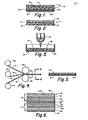
- Figure 1 is a sectional view of a bipolar plate in accordance with the invention;
- Figure 2 is a view in section of a monopolar plate prepared in accordance with the invention;
- Figure 3 is a schematic view of an apparatus for forming a bipolar plate in accordance with the invention;
- Figure 4 is a schematic view of an alternate method for forming a bipolar plate in accordance with the invention;
- Figure 5 is a section taken on line 5-5 of Figure 4; and
- Figure 6 is a view in section of a stack of planar plates forming a battery cell..
- Referring now to Figure 1, the
plate 10 is formed of a composite of an organicsynthetic resin 12 in which is dispersed a sufficient amount of astable filler 14 to provide through-plate conductivity. The preferred material is tin oxide in particulate form, preferably coated onto a particulate support such as glass fibers or glass particles. The glass fibers can be in roving, chopped or glass wool form. In one embodiment, the glass particles are preferably sintered into a solid sheet having a porosity from about 60 to about 90 percent. Theplate 10 preferably has a thickness from about 1 to about 20 mils, more preferably from about 4 to about 10 mils. - The coating of stannic oxide onto glass to form a conductive coating was developed over 30 years ago and has been widely practiced to defrost windshields in aircraft and automobiles. The conductive coating is applied to heated glass fibers or powder or glass wool from a solution of stannic chloride in hydrochloric acid as disclosed in U.S. Patent No. 2,564,707, the disclosure of which is expressly incorporated herein by reference. The solution can be sprayed onto the heated fibers.
- The diameter of the glass fibers is preferably very small such as from about 1 to about 20 microns. Very fine fibers are too hard to handle and large diameter fibers have too small a surface to provide adequate conductive surface. The fibers preferably contain a conductive coating of stannic oxide ranging in thickness from a monolayer up to about 10 microns, more preferably from 0.2 micron to 2 microns.
- Referring now to Figure 2, the through-
conductive plate 10 can be used as the central substrate to form amonolayer plate 11 such as a positive plate containing alayer 18 of positive active material such as lead oxide paste. - Referring back to Figure 1, since tin oxide is not stable in the reducing environment of a negative electrode, the
surface 15 facing the negative electrode must contain alayer 20 that is conductive and stable under reducing conditions. Thelayer 20 can be a composite of a synthetic organic resin such as epoxy or polypropylene containing a dispersion of about 20 to about 70 percent by weight of conductive fibers which are stable under reducing conditions such as graphite fibers or lead fibers. Thelayer 20 can also be a thin film or foil of lead having a thickness from about 0.5 to about 5 mils, preferably from about 1 to about 5 mils. Thelayer 20 can be adhered to theplate 10 by a conductive adhesive such as afilm 21 of graphite-filled epoxy adhesive. The lead foil may be omitted if the conductive layer of epoxy or polypropylene is sufficiently thick to form a good electrolyte barrier. Electrical contact may be improved by applying an electrical current to the foil to slightly melt the foil so that it flows and forms a better contact with the tin oxide coated glass fibers. The fabrication of the bipolar plate is completed by depositing alayer 22 of negative active material such as lead paste onto thelayer 20. - The synthetic
organic resin 12 can be a thermoplastic or thermosetting resin. Representative thermosetting resins are epoxies and polyesters. Preferred thermoplastics are the polyolefins such as polyethylene or polypropylene, and the fluorocarbon resins. Polypropylene is the resin of choice since it has demonstrated long-term stability in lead-acid battery applications. - The conductive plate of the invention can be readily fabricated by casting or roll molding techniques. Referring now to Figure 3, the plate is fabricated by placing a
sheet 30 of lead foil on thebottom surface 32 of thecasting cavity 34. A mixture of molten resin containing at least 20 to 80% by weight of tin oxide coated glass fibers is then poured from mixingkettle 36 onto the cavity. After the resin cools, aconductive layer 38 attached to thelead foil 30 is formed. - Referring now to Figure 4, another apparatus for forming a conductive plate includes a
supply roll 40 of athermoplastic resin 41 such as polypropylene, a supply roll 42 of tin oxide coatedfiberglass fabric 43 and asupply roll 44 oflead foil 45 having an upper surface coated with alayer 46 of a heat curable, conductive adhesive such as an epoxy filled with graphite fibers and/or powder. Thesheet 43 of fiberglass has a thickness slightly less than that of thesheet 41 of polypropylene. When the three sheets are drawn throughheated rollers polypropylene 41 softens. The fabric is pressed onto the softened resin to form acomposite layer 49 and also attaches thefoil 45 to form the assembly as shown in Figure 5. - The following experiments were conducted to evaluate the performance of thin films of stannic oxide in the environment of a lead-acid battery.
- Glass plates were coated with a conductive coating of stannic oxide following the procedure of U.S. Patent No. 3,564,707.
- The stannic oxide coated glass plates of Example 1 were immersed in 5.3 M H2S04 at both 20°C and 50°C. The plates were withdrawn periodically and the resistance of the thin film coating was measured. The results of measurements during 33 days are shown in Table 1.
-

- During that time at both temperatures listed, the resistance change was less than 1/1000 of the film's original condition (day=0). The two samples described in the Table started with different resistance values for the reason that the plates do not have identical dimensions.
- Electrochemical corrosion tests were run utilizing a PARC potentiostat, Model 173, to apply a constant potential to either the cathode or anode in the electrochemical cell. This was done by setting the potential of one of the electrodes relative to a saturated calomel reference electrode (SCE). Two tests were run simultaneously in separate cells. One case corresponded to the SOTF used as an anode (positive terminal) with a fixed potential. The counter electrode was a Pt foil. The second case has the SOTF situated .as the cathode, again using the Pt foil as the counter electrode.
- Shown in Table 2 is the data for ten days of electrochemical tests using SOTF as the anode.

- With a potential of +1.06 V relative to a calomel electrode, the stannic oxide film did not show a change in resistance within the measurement uncertainty of the experimental apparatus.
- The results of using the stannic oxide film as the cathode in the electrochemical cell are shown in Tables 3, 4 and 5.

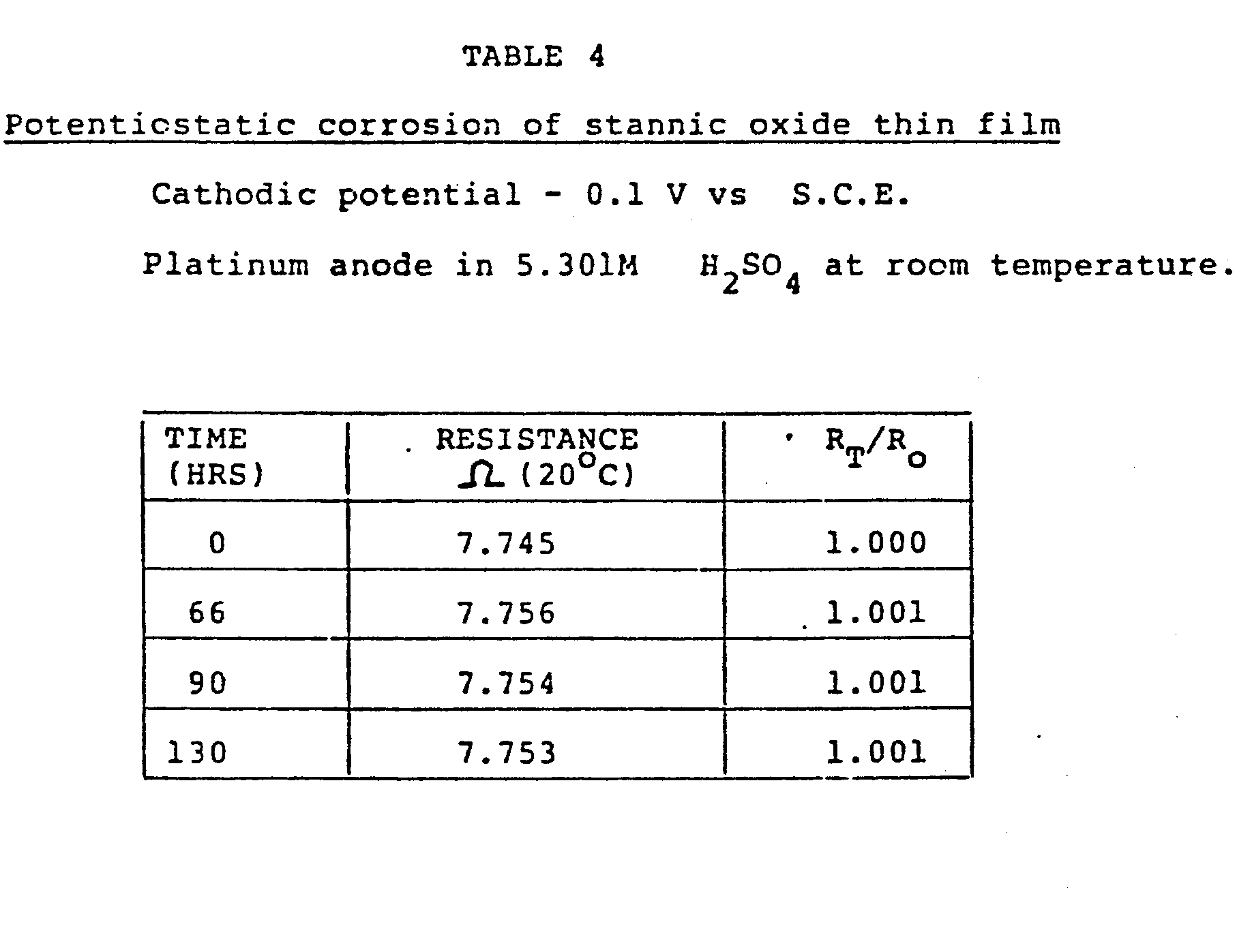

- It was found that significant deterioration occurs at both -0.70 V and -0.35 V. Reducing the potential to -0.10 V stopped the electrochemical corrosion. Over a five day period, there was no measureable change in film resistance.
- After 33 days of conducting chemical corrosion testing, using electrical resistance as the criteria, less than 1/1000 change was detected in the measurements, i.e., the standard deviation is less than 1/1000.. Since the error bar in the measurement may be a maximum 2/1000, a conservative approach to extrapolating the data is to assume an increase of 2/1000 in the film resistance every 30 days. At this rate of degradation, the SOTF (stannic oxide thin film) would take 20 years to double the initial electrical resistance.
- The electrochemical corrosion resistance of the SOTF was determined in an electrochemical cell using the SOTF as either the positive or negative electrode and with Pt foil as the counter electrode. The cell was set up with a saturated calomel reference electrode (SCE) which was used to fix the potential of the SOTF electrode. As before, 5.3 M sulfuric acid was used and all electrochemical tests were run at 20°C. The SOTF electrode (coated glass plate) was removed periodically from the electrochemical cell and measurements were made of the films. Using the SOTF as the anode (positive electrode with a potential of +1.06 V versus SCE), less than 1/1000 change in electrical resistance was measured after 10 days of continuous running. Given this limited data, it would take approximately seven years for the SOTF to double the initial resistance value.
- Another series of experiments were run using SOTF as the cathode (negative electrode) and Pt foil as the anode at 20°C. Initial runs, where the SOTF potential was set to -1.2 V relative to a SCE reference electrode, resulted in a complete degradation or corrosion of the thin film within a time frame of five to ten minutes. Running the electrochemical cell with SOTF at -0.70 V versus SCE and -0.35 V versus SCE resulted in a significant increase in film electrical resistance with time. For the case of -0.70 V, the resistance doubled with a time of 1 hour while for -0.35 V the time for doubling of resistance is estimated to be 14 days. Reducing the SOTF potential further to -0.10 V versus SCE resulted in no noticeable resistance change during five days. Consequently, the threshold potential for degradation of SOTF appears to be between -0.10 V -0.35 V versus SCE. Polarity reversal below -0.10 V must be avoided.
- The plate of the invention is a liquid impervious, low resistance, through-plate conductor having application in any stacked electrochemical cell in which it is desired to provide conduction to an adjacent electrode or an adjacent cell. The plate can be used in batteries, electrolysis cells, fuel cells, electrophoresis cells, etc. The plate can be used in cells with vertically or horizontally disposed cells. The preferred cell configuration is horizontal since horizontal disposition of a cell prevents electrolyte stratification and the continuous, flat surface of the bipolar plate of the invention will prevent shedding of active electrode material, the most prominent failure mode for lead-acid cells.
- A particular, efficient, horizontal battery configuration is disclosed in my copending application, Serial No. 279,841, filed July 2, 1981, entitled BIPOLAR SEPARATE CELL BATTERY FOR HIGH OR LOW VOLTAGE, the disclosure of which is expressly incorporated herein by reference. In that application, bipolar plate groupings are placed between monopolar plates to increase available potential voltage. The conductive plate of the invention can be utilized as a substrate to form either the bipolar plate or a positive monopolar plate of such a battery. A monopolar plate will differ in having the same polarity material provided on each surface thereof, and means to provide lateral conduction to provide for parallel connection to cell groupings.
- Referring now to Figure 6, a
biplate groupings 90 can be assembled surrounding a through-conductive plate 92 of the invention by supporting alayer 94 of positive active lead dioxide material on a firstglass scrim sheet 96 and alayer 98 of negative active sponge lead on asecond sheet 100 of glass scrim. Thesesheets active layers plate 92. The scrim sheets are in turn faced with a porous,fibrous mat 104 suitably formed from glass fibers. The porous mat is capable of releasing any gases formed during operation of the cell and holds the electrolyte. The sheets ofscrim fabric 98. 100 may be bonded to themats 104. By bonding an oppositepolarity scrim sheet mat 104, a bipolar grouping can be assembled by alternating layers ofplates 92 with bipolarporous mat assemblies - The bipolar groupings can be interspersed with monopolar plates connected by bus bars to battery terminals. Alternately, the electrode materials can be plated directly onto the through-conductive substrate plate of the invention. For example, sponge lead can be coated onto one surface and lead dioxide can be coated directly onto the other surface or indirectly onto lead strips coated onto the opposite surface. Bipolar groupings are formed simply by interspersing a porous electrolyte-separator plate between the active material coated bipolar plate. The active materials can be applied as pastes and cured on the scrim or plate according to state of the art procedures. The active materials can also be formed in situ according to the state of the art by applying lead to each surface and then placing the electrode materials in electrolyte and connecting them to a source of potential.
- It is to be realized that only preferred embodiments of the invention have been described and that numerous substitutions, modifications and alterations are permissible without departing from the spirit and scope of the invention as defined in the following claims.
Claims (26)
Applications Claiming Priority (2)
| Application Number | Priority Date | Filing Date | Title |
|---|---|---|---|
| US06/550,875 US4510219A (en) | 1983-11-14 | 1983-11-14 | Battery plate containing filler with conductive coating |
| US550875 | 1990-07-11 |
Publications (3)
| Publication Number | Publication Date |
|---|---|
| EP0142288A2 true EP0142288A2 (en) | 1985-05-22 |
| EP0142288A3 EP0142288A3 (en) | 1986-02-12 |
| EP0142288B1 EP0142288B1 (en) | 1990-04-04 |
Family
ID=24198927
Family Applications (1)
| Application Number | Title | Priority Date | Filing Date |
|---|---|---|---|
| EP84307156A Expired - Lifetime EP0142288B1 (en) | 1983-11-14 | 1984-10-18 | Battery plate containing filler with conductive coating |
Country Status (8)
| Country | Link |
|---|---|
| US (1) | US4510219A (en) |
| EP (1) | EP0142288B1 (en) |
| JP (1) | JPS60175376A (en) |
| BR (1) | BR8405800A (en) |
| CA (1) | CA1238682A (en) |
| DE (1) | DE3481881D1 (en) |
| DK (1) | DK537884A (en) |
| NO (1) | NO844367L (en) |
Cited By (3)
| Publication number | Priority date | Publication date | Assignee | Title |
|---|---|---|---|---|
| DE4300763C2 (en) * | 1993-01-14 | 2000-09-07 | Varta Batterie | Lead accumulator with at least one bipolar electrode |
| DE102007014752A1 (en) | 2007-03-28 | 2008-10-02 | Dusek, Niels, Dr. | Interleukin for use with human identical amino acid sequence and glycosyl residue for use as therapeutic agent for bacterial infections, sepsis, mycoplasma disease, autoimmune disease and multiple sclerosis in humans and animals |
| EP4224569A4 (en) * | 2020-09-30 | 2025-06-25 | Furukawa Electric Co., Ltd. | Bipolar lead-acid battery |
Families Citing this family (66)
| Publication number | Priority date | Publication date | Assignee | Title |
|---|---|---|---|---|
| US5126218A (en) * | 1985-04-23 | 1992-06-30 | Clarke Robert L | Conductive ceramic substrate for batteries |
| US5316846A (en) * | 1986-03-24 | 1994-05-31 | Ensci, Inc. | Coated substrates |
| US5112706A (en) * | 1986-03-24 | 1992-05-12 | Ensci, Inc. | Coated substrates |
| US5182165A (en) * | 1986-03-24 | 1993-01-26 | Ensci, Inc. | Coating compositions |
| US5326633A (en) * | 1986-03-24 | 1994-07-05 | Ensci, Inc. | Coated substrates |
| US5204140A (en) * | 1986-03-24 | 1993-04-20 | Ensci, Inc. | Process for coating a substrate with tin oxide |
| US5352517A (en) * | 1986-03-24 | 1994-10-04 | Ensci, Inc. | Iron oxide coated substrates |
| US5549990A (en) * | 1986-03-24 | 1996-08-27 | Ensci Inc | Battery element containing porous particles |
| US5601945A (en) * | 1986-03-24 | 1997-02-11 | Ensci Inc. | Battery element containing porous substrates |
| US5317132A (en) * | 1986-03-24 | 1994-05-31 | Ensci, Inc. | Heating elements containing electrically conductive tin oxide containing coatings |
| US5290589A (en) * | 1986-03-24 | 1994-03-01 | Ensci, Inc. | Process for coating a substrate with iron oxide and uses for coated substrates |
| US5264012A (en) * | 1986-03-24 | 1993-11-23 | Ensci Inc. | Gas separation process |
| US5398153A (en) * | 1986-03-24 | 1995-03-14 | Ensci, Inc. | Electrostatic dissipation and electromagnetic interference shielding elements |
| US5271858A (en) * | 1986-03-24 | 1993-12-21 | Ensci Inc. | Field dependent fluids containing electrically conductive tin oxide coated materials |
| US4708918A (en) * | 1986-03-24 | 1987-11-24 | Ensci, Inc. | Battery element and battery incorporating polar polymer system |
| US5039845A (en) * | 1986-03-24 | 1991-08-13 | Ensci, Inc. | Resistance heating element and methods for resistance heating |
| US5167820A (en) * | 1986-03-24 | 1992-12-01 | Ensci, Inc. | Porous membranes and methods for using same |
| US5633081A (en) * | 1986-03-24 | 1997-05-27 | Ensci Inc. | Coated porous substrates |
| US5705265A (en) * | 1986-03-24 | 1998-01-06 | Emsci Inc. | Coated substrates useful as catalysts |
| CA1307026C (en) * | 1986-03-24 | 1992-09-01 | Naum Pinsky | Battery element and battery incorporating doped tin oxide coated substrate |
| US5603983A (en) * | 1986-03-24 | 1997-02-18 | Ensci Inc | Process for the production of conductive and magnetic transitin metal oxide coated three dimensional substrates |
| US4861689A (en) * | 1987-11-23 | 1989-08-29 | Ensci, Inc. | Battery element and method for making same |
| US5106709A (en) * | 1990-07-20 | 1992-04-21 | Globe-Union Inc. | Composite substrate for bipolar electrode |
| JPH04248274A (en) * | 1991-01-25 | 1992-09-03 | Mitsui Eng & Shipbuild Co Ltd | Layer-built cell |
| US5643696A (en) * | 1991-07-22 | 1997-07-01 | Bipolar Power Corporation | Battery plates with lightweight cores |
| US5334464A (en) * | 1991-07-22 | 1994-08-02 | Bipolar Power Corporation | Lightweight battery plates |
| US5645959A (en) * | 1992-08-20 | 1997-07-08 | Bipolar Power Corporation | Battery plates with self-passivating iron cores and mixed acid electrolyte |
| CN1091553A (en) * | 1992-11-20 | 1994-08-31 | 国家标准公司 | The matrix of battery electrode and manufacture method thereof |
| US5368960A (en) * | 1993-07-23 | 1994-11-29 | Rowlette; John J. | Utilization efficiencies by using high sulfate starting materials |
| US5648137A (en) * | 1994-08-08 | 1997-07-15 | Blackmore; Richard | Advanced cured resin composite parts and method of forming such parts |
| US6146576A (en) * | 1994-08-08 | 2000-11-14 | Intralaminar Heat Cure, Inc. | Method of forming advanced cured resin composite parts |
| US7052567B1 (en) | 1995-04-28 | 2006-05-30 | Verline Inc. | Inflatable heating device for in-situ repair of conduit and method for repairing conduit |
| US5606997A (en) * | 1995-04-28 | 1997-03-04 | Advance Trenchless Rehabilitation Systems | Method for rehabilitating pipe line and resin impregnated lining having an integral heating element |
| DE19915378A1 (en) * | 1999-04-06 | 2000-10-12 | Inst Neue Mat Gemein Gmbh | Household appliances with a catalytic composition |
| DE19915377A1 (en) | 1999-04-06 | 2000-10-12 | Inst Neue Mat Gemein Gmbh | Catalytic composition, process for its preparation and its use |
| JP2003524281A (en) * | 1999-10-06 | 2003-08-12 | スクワナクック テクノロジーズ エルエルシー | Battery paste |
| US6531248B1 (en) | 1999-10-06 | 2003-03-11 | Squannacook Technologies Llc | Battery paste |
| US7968251B2 (en) | 2000-11-24 | 2011-06-28 | GM Global Technology Operations LLC | Electrical contact element and bipolar plate |
| DE10058337A1 (en) * | 2000-11-24 | 2002-05-29 | Gen Motors Corp | Sheet product used as a bipolar plate in a fuel cell or in an electrolyzer has a conductive corrosion resistant protective coating made from a metal oxide on one side. |
| US20030165731A1 (en) * | 2002-03-01 | 2003-09-04 | Gayatri Vyas | Coated fuel cell electrical contact element |
| ATE417369T1 (en) * | 2001-01-19 | 2008-12-15 | Atraverda Ltd | ELECTRODE FOR A BATTERY |
| US6607857B2 (en) | 2001-05-31 | 2003-08-19 | General Motors Corporation | Fuel cell separator plate having controlled fiber orientation and method of manufacture |
| US6827747B2 (en) * | 2002-02-11 | 2004-12-07 | General Motors Corporation | PEM fuel cell separator plate |
| US7159805B2 (en) * | 2002-03-25 | 2007-01-09 | Evanite Fiber Corporation | Methods of modifying fibers |
| US6929858B2 (en) * | 2002-03-25 | 2005-08-16 | Squannacook Technologies Llc | Glass fibers |
| US20030198857A1 (en) * | 2002-04-05 | 2003-10-23 | Mcmanus Edward C. | Graphite laminate fuel cell plate |
| SE526652C2 (en) * | 2003-03-04 | 2005-10-18 | Effpower Ab | Partition wall for bipolar battery electrode, bipolar electrode, bipolar battery and method for manufacturing partition for bipolar battery electrode |
| US8455155B2 (en) * | 2006-11-22 | 2013-06-04 | GM Global Technology Operations LLC | Inexpensive approach for coating bipolar plates for PEM fuel cells |
| CN100549474C (en) * | 2007-12-21 | 2009-10-14 | 浙江国泰密封材料股份有限公司 | Netted metallic reinforced sealing plate and production method thereof |
| JP2009161499A (en) * | 2008-01-10 | 2009-07-23 | Sumitomo Chemical Co Ltd | Process for producing 2-hydroxy-4-methylthiobutanamide |
| EP2389698B1 (en) * | 2009-01-21 | 2017-10-04 | Advanced Battery Concepts, Llc | Bipolar battery assembly |
| US20110059340A1 (en) * | 2009-05-19 | 2011-03-10 | Dougherty Thomas J | Conductive Plastic Bipolar Battery or Capacitor with Siloxane Electrolyte |
| US10446822B2 (en) | 2011-10-24 | 2019-10-15 | Advanced Battery Concepts, LLC | Bipolar battery assembly |
| US9685677B2 (en) | 2011-10-24 | 2017-06-20 | Advanced Battery Concepts, LLC | Bipolar battery assembly |
| US10141598B2 (en) | 2011-10-24 | 2018-11-27 | Advanced Battery Concepts, LLC | Reinforced bipolar battery assembly |
| US10615393B2 (en) | 2011-10-24 | 2020-04-07 | Advanced Battery Concepts, LLC | Bipolar battery assembly |
| EP3288099B1 (en) | 2011-10-24 | 2021-01-06 | Advanced Battery Concepts, LLC | Bipolar battery assembly |
| WO2015125413A1 (en) * | 2014-02-20 | 2015-08-27 | 三洋電機株式会社 | Battery case and battery |
| DE102017109621A1 (en) * | 2017-05-04 | 2018-11-08 | Deutsches Zentrum für Luft- und Raumfahrt e.V. | Electric device in stack construction |
| CN108281671B (en) * | 2017-12-28 | 2020-11-10 | 广州倬粤动力新能源有限公司 | Co-extruded grid fiber composite line |
| US12107253B2 (en) | 2018-11-15 | 2024-10-01 | Advanced Battery Concepts, LLC | Active materials useful in balancing power and energy density of a battery assembly |
| KR20220004698A (en) | 2019-05-24 | 2022-01-11 | 어드밴스드 배터리 컨셉츠, 엘엘씨 | Battery Assemblies with Integrated Edge Seals and Methods of Forming the Seals |
| CN110224142A (en) * | 2019-07-03 | 2019-09-10 | 周诚悦 | A kind of netting casting type lead-acid battery anode grid and preparation method thereof |
| JP2023518236A (en) | 2020-03-16 | 2023-04-28 | アドバンスト バッテリー コンセプツ エルエルシー | BATTERY ASSEMBLY, METHOD OF MAKING AND THERMAL CONTROL THEREOF |
| JPWO2022201834A1 (en) * | 2021-03-26 | 2022-09-29 | ||
| CN115377362A (en) * | 2022-09-20 | 2022-11-22 | 湖北小凡智造科技有限公司 | Forming type lead-acid storage battery pole plate and preparation method of lead-acid storage battery |
Family Cites Families (21)
| Publication number | Priority date | Publication date | Assignee | Title |
|---|---|---|---|---|
| US2564707A (en) * | 1947-09-03 | 1951-08-21 | Corning Glass Works | Electrically conducting coatings on glass and other ceramic bodies |
| FR1181142A (en) * | 1957-08-13 | 1959-06-11 | Const Mecaniques De Stains Soc | Manufacturing process for plates and other lead elements reinforced with mineral fibers |
| GB956553A (en) * | 1959-05-12 | 1964-04-29 | Eisler Paul | Storage battery |
| FR1363861A (en) * | 1960-05-16 | 1964-06-19 | Accumulateurs Fixes | Process for manufacturing electrodes for accumulators, fuel cells, etc., and electrodes thus obtained |
| US3256596A (en) * | 1961-02-06 | 1966-06-21 | William S Fiedler | Process for making article of vitreous material and metal |
| US3466193A (en) * | 1967-05-01 | 1969-09-09 | Gen Motors Corp | Storage battery positive plate with lead fibers |
| GB1207989A (en) * | 1967-07-19 | 1970-10-07 | Ici Ltd | Grids for the plates of secondary cells and batteries |
| GB1314891A (en) * | 1970-07-14 | 1973-04-26 | Ici Ltd | Grids for the electrodes of secondary cells and batteries |
| GB1394681A (en) * | 1971-04-06 | 1975-05-21 | Ici Ltd | Electrodes |
| US3738871A (en) * | 1971-05-06 | 1973-06-12 | Scholle Corp | Storage battery plates of plastic and lead |
| US3819412A (en) * | 1972-02-07 | 1974-06-25 | Tyco Laboratories Inc | Plates for lead acid batteries |
| DE2250187A1 (en) * | 1972-10-13 | 1974-04-25 | Varta Batterie | LEAD ACCUMULATOR WITH BIPOLAR ELECTRODES |
| CA1051512A (en) * | 1973-05-23 | 1979-03-27 | Royce E. Biddick | Bipolar electrode using electrically conductive plastic substrate containing vitreous carbon |
| FR2271674A1 (en) * | 1974-05-17 | 1975-12-12 | Comp Generale Electricite | Lead acid accumulator plates - have reduced electrode weight using a titanium matrix in a lead sandwich |
| US4125680A (en) * | 1977-08-18 | 1978-11-14 | Exxon Research & Engineering Co. | Bipolar carbon-plastic electrode structure-containing multicell electrochemical device and method of making same |
| JPS55126963A (en) * | 1979-03-23 | 1980-10-01 | Yuasa Battery Co Ltd | Plate for lead-acid battery |
| US4275130A (en) * | 1979-09-27 | 1981-06-23 | California Institute Of Technology | Bipolar battery construction |
| US4339322A (en) * | 1980-04-21 | 1982-07-13 | General Electric Company | Carbon fiber reinforced fluorocarbon-graphite bipolar current collector-separator |
| JPS6054745B2 (en) * | 1980-04-23 | 1985-12-02 | 東レ株式会社 | lead acid battery |
| US4326017A (en) * | 1981-01-26 | 1982-04-20 | General Electric Company | Positive electrode for lead acid battery |
| US4547443A (en) * | 1983-11-14 | 1985-10-15 | Atlantic-Richfield Company | Unitary plate electrode |
-
1983
- 1983-11-14 US US06/550,875 patent/US4510219A/en not_active Expired - Lifetime
-
1984
- 1984-10-12 CA CA000465369A patent/CA1238682A/en not_active Expired
- 1984-10-18 EP EP84307156A patent/EP0142288B1/en not_active Expired - Lifetime
- 1984-10-18 DE DE8484307156T patent/DE3481881D1/en not_active Expired - Lifetime
- 1984-11-02 NO NO844367A patent/NO844367L/en unknown
- 1984-11-13 DK DK537884A patent/DK537884A/en not_active Application Discontinuation
- 1984-11-13 BR BR8405800A patent/BR8405800A/en unknown
- 1984-11-14 JP JP59238710A patent/JPS60175376A/en active Pending
Cited By (3)
| Publication number | Priority date | Publication date | Assignee | Title |
|---|---|---|---|---|
| DE4300763C2 (en) * | 1993-01-14 | 2000-09-07 | Varta Batterie | Lead accumulator with at least one bipolar electrode |
| DE102007014752A1 (en) | 2007-03-28 | 2008-10-02 | Dusek, Niels, Dr. | Interleukin for use with human identical amino acid sequence and glycosyl residue for use as therapeutic agent for bacterial infections, sepsis, mycoplasma disease, autoimmune disease and multiple sclerosis in humans and animals |
| EP4224569A4 (en) * | 2020-09-30 | 2025-06-25 | Furukawa Electric Co., Ltd. | Bipolar lead-acid battery |
Also Published As
| Publication number | Publication date |
|---|---|
| NO844367L (en) | 1985-05-15 |
| CA1238682A (en) | 1988-06-28 |
| DE3481881D1 (en) | 1990-05-10 |
| EP0142288A3 (en) | 1986-02-12 |
| BR8405800A (en) | 1985-09-17 |
| US4510219A (en) | 1985-04-09 |
| JPS60175376A (en) | 1985-09-09 |
| DK537884D0 (en) | 1984-11-13 |
| EP0142288B1 (en) | 1990-04-04 |
| DK537884A (en) | 1985-05-15 |
Similar Documents
| Publication | Publication Date | Title |
|---|---|---|
| US4510219A (en) | Battery plate containing filler with conductive coating | |
| US4547443A (en) | Unitary plate electrode | |
| US4625395A (en) | Battery plate containing filler with conductive coating | |
| US4542082A (en) | Bipolar battery plate | |
| US4658499A (en) | Bipolar battery plate | |
| US5348817A (en) | Bipolar lead-acid battery | |
| US4275130A (en) | Bipolar battery construction | |
| EP0268397B1 (en) | Carbon-plastic electrode elements | |
| US5705259A (en) | Method of using a bipolar electrochemical storage device | |
| EP2313353B1 (en) | Method for producing an electrode for lead-acid battery | |
| US3486940A (en) | Storage battery having a positive electrode comprising a supporting base of titanium nitride having a surface film of non-polarizing material | |
| US4507372A (en) | Positive battery plate | |
| EP0352115B1 (en) | Lead-acid battery | |
| EP1866988B1 (en) | Current carrier for an energy storage device | |
| EP1573836A2 (en) | Composite material and current collector for battery | |
| US4787125A (en) | Battery element and battery incorporating doped tin oxide coated substrate | |
| EP1261049B1 (en) | Electrode grid for lead acid batteries coated with a conductive polymeric matrix and method of manufacture | |
| US3556855A (en) | Battery with a grid of metal coated fibres and resin | |
| CN111682218B (en) | Enhanced carbon-containing material current collector and preparation method thereof | |
| US4717633A (en) | Electrode structure for lightweight storage battery | |
| Perkins | Materials and mechanisms determining the performance of lead-acid storage batteries an invited review | |
| US4873161A (en) | Positive paste with lead-coated glass fibers | |
| EP0360942A1 (en) | Conductive ceramic support for active material in a lead-acid storage battery | |
| Rowlette et al. | Unitary plate electrode | |
| Rowlette | Bipolar battery plate |
Legal Events
| Date | Code | Title | Description |
|---|---|---|---|
| PUAI | Public reference made under article 153(3) epc to a published international application that has entered the european phase |
Free format text: ORIGINAL CODE: 0009012 |
|
| AK | Designated contracting states |
Designated state(s): BE DE FR GB IT |
|
| PUAL | Search report despatched |
Free format text: ORIGINAL CODE: 0009013 |
|
| AK | Designated contracting states |
Designated state(s): BE DE FR GB IT |
|
| 17P | Request for examination filed |
Effective date: 19860806 |
|
| 17Q | First examination report despatched |
Effective date: 19880211 |
|
| GRAA | (expected) grant |
Free format text: ORIGINAL CODE: 0009210 |
|
| AK | Designated contracting states |
Kind code of ref document: B1 Designated state(s): BE DE FR GB IT |
|
| PG25 | Lapsed in a contracting state [announced via postgrant information from national office to epo] |
Ref country code: IT Free format text: LAPSE BECAUSE OF FAILURE TO SUBMIT A TRANSLATION OF THE DESCRIPTION OR TO PAY THE FEE WITHIN THE PRESCRIBED TIME-LIMIT;WARNING: LAPSES OF ITALIAN PATENTS WITH EFFECTIVE DATE BEFORE 2007 MAY HAVE OCCURRED AT ANY TIME BEFORE 2007. THE CORRECT EFFECTIVE DATE MAY BE DIFFERENT FROM THE ONE RECORDED. Effective date: 19900404 Ref country code: BE Effective date: 19900404 |
|
| REF | Corresponds to: |
Ref document number: 3481881 Country of ref document: DE Date of ref document: 19900510 |
|
| ET | Fr: translation filed | ||
| PGFP | Annual fee paid to national office [announced via postgrant information from national office to epo] |
Ref country code: FR Payment date: 19900824 Year of fee payment: 7 |
|
| PLBE | No opposition filed within time limit |
Free format text: ORIGINAL CODE: 0009261 |
|
| STAA | Information on the status of an ep patent application or granted ep patent |
Free format text: STATUS: NO OPPOSITION FILED WITHIN TIME LIMIT |
|
| 26N | No opposition filed | ||
| PGFP | Annual fee paid to national office [announced via postgrant information from national office to epo] |
Ref country code: GB Payment date: 19910813 Year of fee payment: 8 |
|
| PGFP | Annual fee paid to national office [announced via postgrant information from national office to epo] |
Ref country code: DE Payment date: 19911028 Year of fee payment: 8 |
|
| PG25 | Lapsed in a contracting state [announced via postgrant information from national office to epo] |
Ref country code: FR Effective date: 19920630 |
|
| REG | Reference to a national code |
Ref country code: FR Ref legal event code: ST |
|
| PG25 | Lapsed in a contracting state [announced via postgrant information from national office to epo] |
Ref country code: GB Effective date: 19921018 |
|
| GBPC | Gb: european patent ceased through non-payment of renewal fee |
Effective date: 19921018 |
|
| PG25 | Lapsed in a contracting state [announced via postgrant information from national office to epo] |
Ref country code: DE Effective date: 19930701 |